Close
0%
0%

Eazy Peasy High Voltage Variable Capacitor

3D printed fixed and variable capacitors. Simple theory, simple methods. But don't build it this way! See why by reading the project.

Similar projects worth following
I built an efficient loop antenna for ham radio (see earlier project). I wanted to build my own variable capacitor with about 15 or 20 pF range for the loop that tolerates a 100 W transmitter. The following describes building and testing. Along the way, I built a DC motor controller for remote control of the capacitor.

While this capacitor does work, it will not handle 100 W. See my newer capacitor designs. Don't skip this project. It covers a lot of basics of how to design and build a capacitor.

I discuss the problem with this capacitor design in my discussion of 5 plate and 7 plate capacitors.

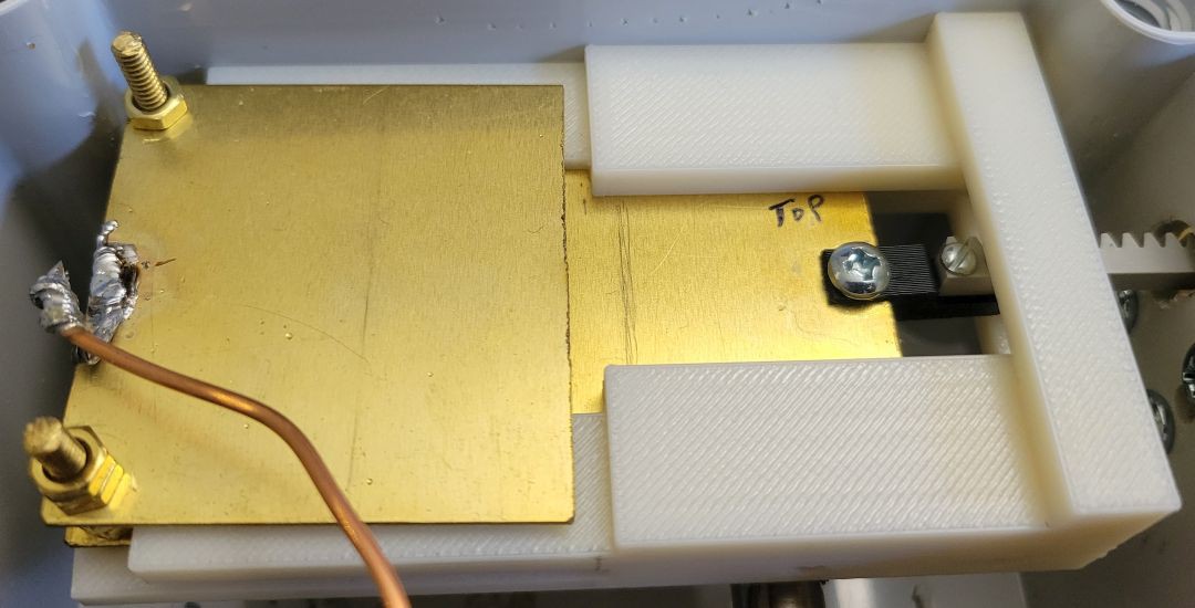
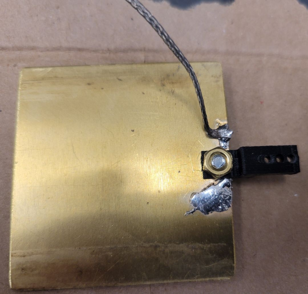
The main part of this project is a very simple home made variable capacitor. You can design it for a wide range of capacitance and voltage values. I give an example for a 15 pF capacitor that will tolerate over 3500 volts. It requires one 3D printed part and the rest is easy peasy.

The remainder of the project is testing and some more advanced stuff, like remote tuning with a DC motor and an Arduino.

Plate slide v3.stl

3D printed frame to make 20 pF capacitor

Standard Tesselated Geometry - 54.48 kB - 03/11/2022 at 16:17

Download

Linear capacitor arm v1.stl

Simple coupling device to connect sliding plate to push-rod of any sort.

Standard Tesselated Geometry - 6.92 kB - 03/11/2022 at 19:19

Download

Motor mount block v3.stl

Mount for optional motor drive of capacitor.

Standard Tesselated Geometry - 97.35 kB - 03/13/2022 at 01:12

Download

  • 1 × 6-32 threaded brass rod McMaster-Carr 98812A602
  • 1 × 6-32 brass nut (narrow) McMaster-Carr 95130A120
  • 1 × 2" wide brass sheet (.04" thick) McMaster-Carr 8956K432

  • Works as advertised, but see the next project

    Andrew Mitz12/26/2022 at 16:21 0 comments

    While this is a great little homebrew capacitor, it handles 100 W only because it uses a larger fixed capacitor in parallel. Most of the energy is absorbed by the larger capacitor. When I tried to expand this to more plates, the capacitor arced when running 100 W. The plastic in-between plates acts as a dielectric.  It raises the the electric field between plates. That is not a bad thing, but the air in the tiny air gaps between the plastic and the plates breaks down and starts an arc. The arcing leads to burned plastic. The only solution is to remove all plastic from between the plates. This calls for a new design where the 3D printed parts are an exoskeleton for the fixed and moving plates. See the next project on how to design a multi-plate high voltage RF capacitor. The rack and pinion are replaced by a motor with a lead screw. This is the design I use all the time now. 

  • Instructions for making the capacitor are simple

    Andrew Mitz03/22/2022 at 22:23 0 comments

    The capacitor is easy to make, especially if you just want to duplicate my capacitor by printing the provided STL file. The instructions have an introduction that provides enough information to design your own fixed or variable capacitor, should you need a different capacitance range. If you have any questions about designing your own version of the capacitor, feel free to contact me. 

    Since the instructions are so simple, I went ahead and wrote up my design for a motor with rack-and-pinion to move the capacitor. 

    Since that was so simple, I went ahead and introduced my Arduino controller for the motor.  The motor controller is a work in progress. 

View all 2 project logs

  • 1
    Introduction and a very simple STEP 1

    Introduction

    This design uses rectangular brass plates cut from one long sheet. The amount of overlap between plates and the spacing between plates determine the capacitance. In this design, we use 3.06 mm thick brass nuts on threaded rod to space the plates apart. Thus, there are only 3 things to decide:

    1. The length of the cut sheet
    2. The number of brass nuts between sheets
    3.  The number of sheets that will be interdigitated with each other.

    A fixed capacitor to explain how it works

    Let me explain the design using a fixed capacitor.  My variable capacitor is actually simpler, but going over this design is helpful for explaining. This diagram shows the arrangement, dimensions and equation for a fixed capacitor. Some of the parts are in imperial units (e.g., inches), but I convert everything to millimeters to make the calculations easier. 

    The brass plates are held together by the threaded brass rods and insulators on the ends. (Plexiglas makes a great insulator.) Each brass plate has 2 holes. When the nuts are tightened, the structure is rigid. I will not discuss the relationship between breakdown voltage and plate spacing right now, but the spacing must be wide enough to tolerate the voltage you will be using. The capacitance is calculated as C (in the figure) times the number of sections of the capacitor.  You can build a capacitor like this in an hour or two. It takes a hacksaw, drill, file and some wrenches.

    Example

    The figure has plates that overlap each other by 40 mm. Each plate is 50.8 mm wide.  Thus, the area of each overlapping plate is 40 x 50.8 = 2032 mm2.  The spacing is 3 nuts. Subtracting out the thickness of a plate, the nuts produce a gap between any two plates of 3.06 mm.  The capacitor has 4 sections (4 gaps between plates).  

    Simplified equation

    We can ignore the k value, since it is 1 for air.  The value for ɛ is in Farads/meter. That is annoying. Fortunately, we can just throw away the exponent to get picoFarads (pF). ɛ = 8.85 pF/m.  For mm, we divide by 1000: 

    ɛ = 0.00885 pF/mm. I will round it to 0.009 pF/mm.  Now the equation is much simpler.

    C =  0.009 * (Area / Distance) * sections   (all in mm)

    For this example with 4 sections

    C = 0.009 * 2032/3.06 * 4

      = 24 pF

    A simple variable capacitor

    To make a variable capacitor, you need a structure that lets you move one set of plates. In my design, I move one plate in between two fixed plates, in a simple linear fashion. Most traditional capacitors rotate. Mine is linear for two reasons:

    1.  A 3D printed frame makes assembly very easy.
    2. The moving plate can have a soldered wire for a very low impedance connection. This is especially important for loop antennas.

    Here is the basic design of the linear capacitor. Note how simple it is.  The fixed plates are spaced by 3 brass nuts. The sliding plate goes in between. 

    This design has 2 sections: section 1 is the capacitance between the sliding plate and the top plate, section 2 is the capacitance between the sliding plate and the bottom plate. The spacing is 3.06 mm, based on the thickness of these brass nuts and the thickness of the sliding plate. The plates are 50.8 mm wide (made from 2" wide brass sheet). Together, two sections gives you just under 0.3 pF for each mm of overlap. For my purposes, 40 mm overlap should provide 12 pF. In practice, the capacitance is a little higher. 

    Here is Step 1 

    • Cut 3 plates from the brass stock. The plates should be long enough for the 40 mm of overlap and to drill holes for the threaded brass support rods. 
    • Cut two lengths of threaded rod 
    • We will need 12 nuts for the fixed plates and two for the sliding plate. 

    The drawing shows two nuts for the sliding plate, but we will revisit how the sliding plate is attached. 

  • 2
    3D printed frame

    The 3D printed plastic holder is used to support the two fixed plates and provide a path for the sliding plate.

    The STL file is in the Files section of this project. You can use it to make a 15 pF capacitor, or use it as a guide to designing your own. 

    After cutting and drilling the brass plates, the edges of the plates should be smoothed with a file. The fixed plates should mount easily on two threaded rods using the correct number of nuts to keep them spaced. The moving plate should ride easily along the guide. The mounting holes are for 8-32 screws.  Mounting can be done with 2 side screws (there are two on either side) or the two front screws. 

  • 3
    Mechanical and electrical connections

    The Files section has a STL file for printing a simple coupling. The coupler proved handy for attaching to a motor. However, almost any type of insulated coupling can be used. The coupler can be seen in the picture.

    Electrical connections can be done in several ways. The fixed plates can be screwed to a solderless lug or soldered to a wire. It is best to solder the threaded rod when not assembled to the printed plastic piece. I opted to use wire braid for both the moving plate and the fixed plates.  You can see the braid coming from the sliding plate in the picture above. You can see the braid on the fixed plate, below. The braid goes only a short distance to a heavy solid copper wire. This is inside of a tuning unit for a 100 W loop antenna, so low impedance connections are important. 

    The underside of the moving plate. 

    The braid is positioned so that it moves freely without touching other components when the moving plate is moved. 

    Construction is done!

    The Easy Peasy variable capacitor is done!  However, while you are here, we are going to dig deeper into testing and remote control. 

View all 7 instructions

Enjoy this project?

Share

Discussions

Similar Projects

Does this project spark your interest?

Become a member to follow this project and never miss any updates