 looperTwentyThree
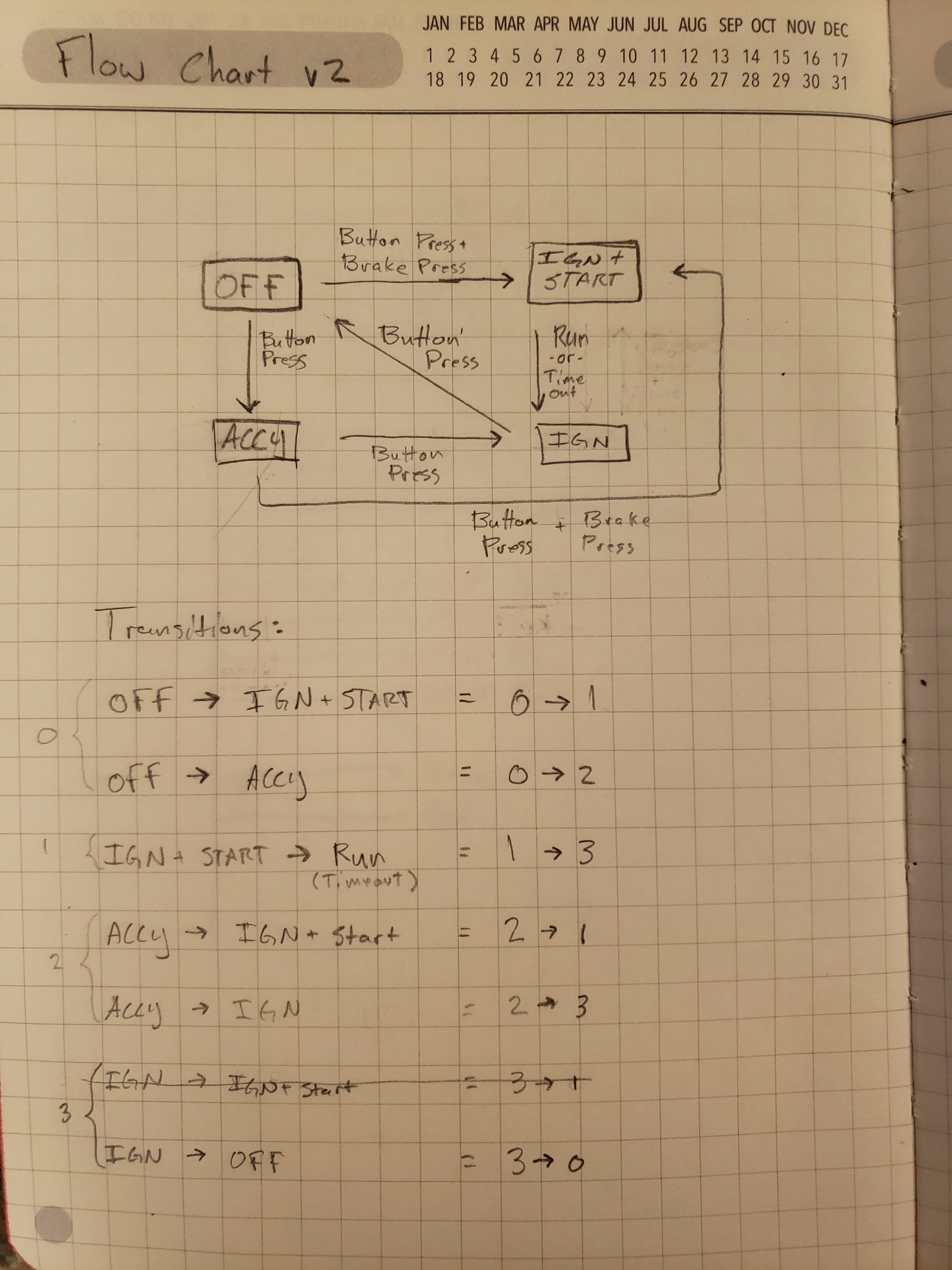
This project was inspired by the keyless remote start system that is featured in my car. I became curious as to how the system worked from a logic standpoint. To start out, I mapped out how many states the system it could be in by just pressing the start/stop button with and without the brake pedal pressed, with and without the car in park, and with the key fob in and out of range of the car. The results I got seemed to map out as shown:
Now, I didn't want to go tearing apart anything to verify the hardware of the system, however I am going to make some assumptions about that portion of the car's electrical system:
1. The start/stop module must contain some RFID or NFC transponder that communicates to key fobs in close proximity. I appears that there are two modes: active and passive. Active mode range is about three feet from the antenna (in the center console). In passive mode (i.e. dead battery) The particular car that I have has a slot you can put the key fob into that is right next to the antenna. That is the only way you can turn on the ignition when the fob's battery is dead as stated in the owner's manual.
2. The controller has a very low power mode. I am not sure if the press of the start/stop button turns on the controller, or if the controller wakes on other events such as door unlock, etc. to be ready for the button press. mimicking something like this with an Arduino could be present several options that I'll get into later.
3. The controller is built for the extremes: It has operated flawlessly in extremely hot and low temperatures, as well been able to handle the task of starting on an almost dead battery. I could imagine dust, humidity and vibration are also long term problems that were mitigated, however without tearing into the dash I wouldn't know how those problems were solved.
Starting with a proof of concept, I pulled out the 'ol Arduino and a breadboard to see if I could build the basics with regular components.
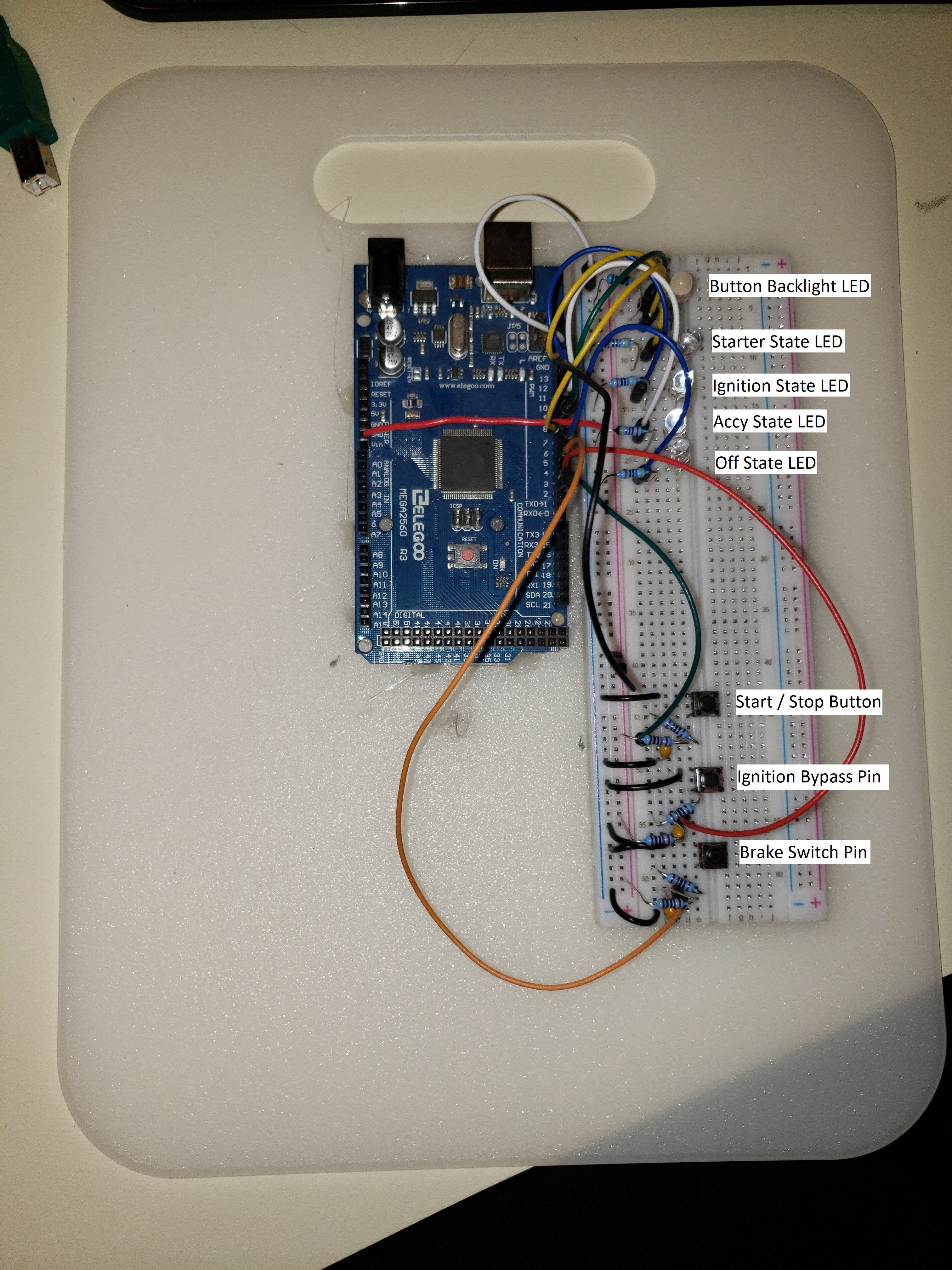
Viola! A working concept! Following the state diagram I drew out, I programmed the Arduino to read the states of the inputs (start/stop button, brake s/w, and ignition pin) and jump to another state depending upon the applicable states. At the end of the routine, a change in state would adjust the output pins accordingly, represented by the red LED's.
Several initial challenges that I had to think about were:
1. How will the controller know to disengage the starter?
This would be an application specific problem, in my case, I am interested in designing this to go into an old Chevy truck that has an 8-pin distributor mounted ignitor module. One of the pins lets the ECM know that it's above 400 rpm for timing curve control purposes. I propose tapping off that pin (since its 5v logic) to go to an input pin on the Arduino.
I would be curious to hear what other people would say about vehicle security, but for the purposes of putting something together and doing some initial testing installed in a car, I would think that a simple RFID module that has a range of one meter would be enough. Something like a PN5180 might work well for the application since it works with the ISO 15693 "vicinity card" protocol.

 sjm4306
 tEEonE
 Rob Smith
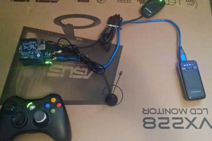
 barrettrouton