 Xtreme Tech
Basic functioning of this project:
This video game console can run one video game (Diamond Dash) where the player must collect diamonds within the time limit to win.
More about this project:
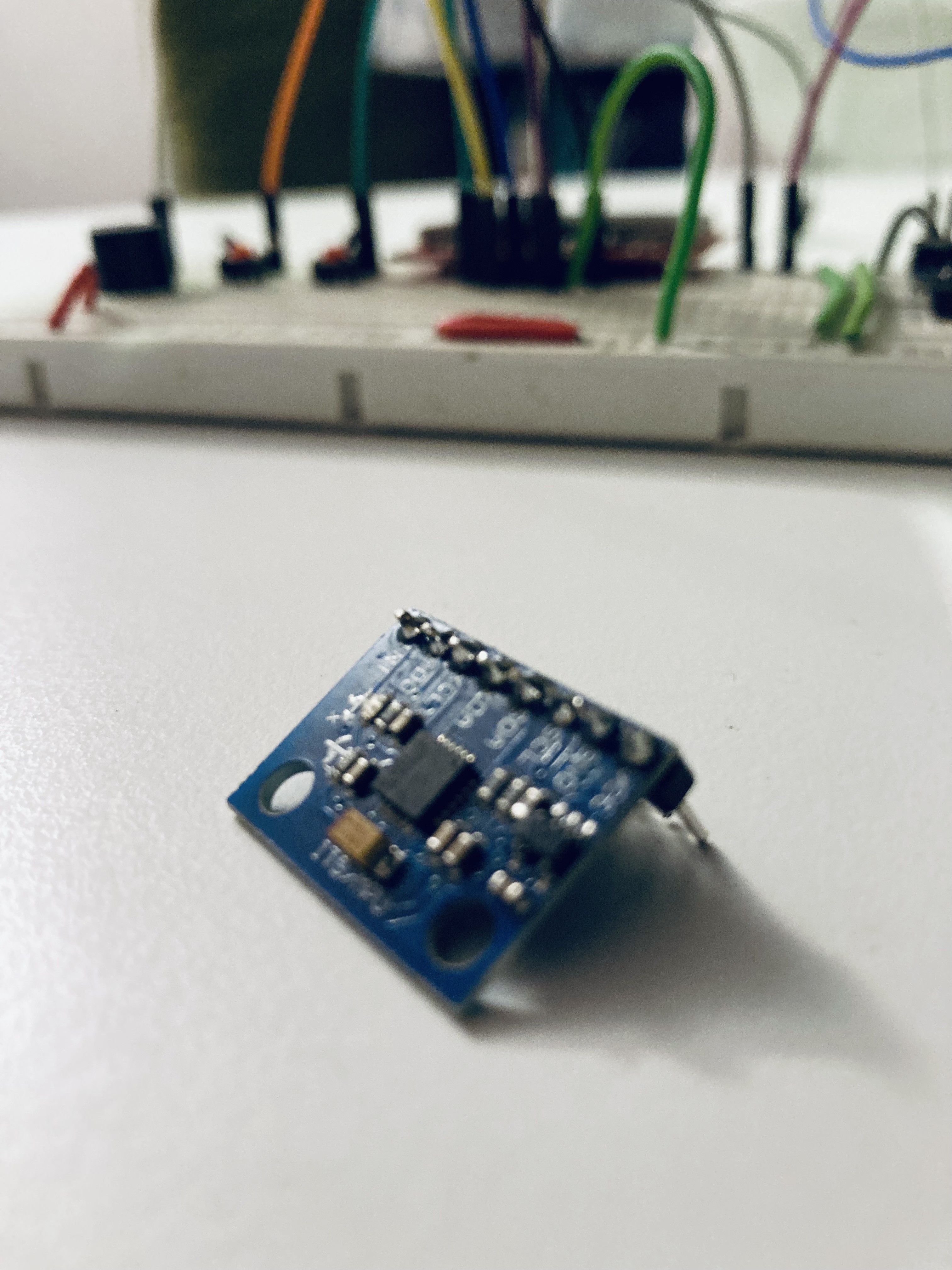
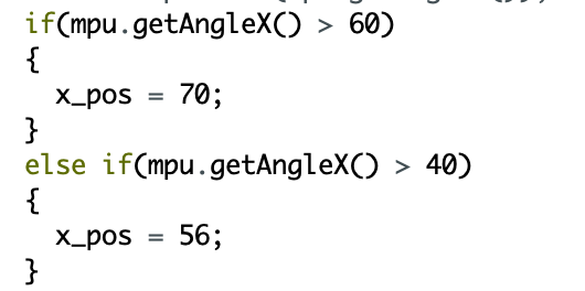
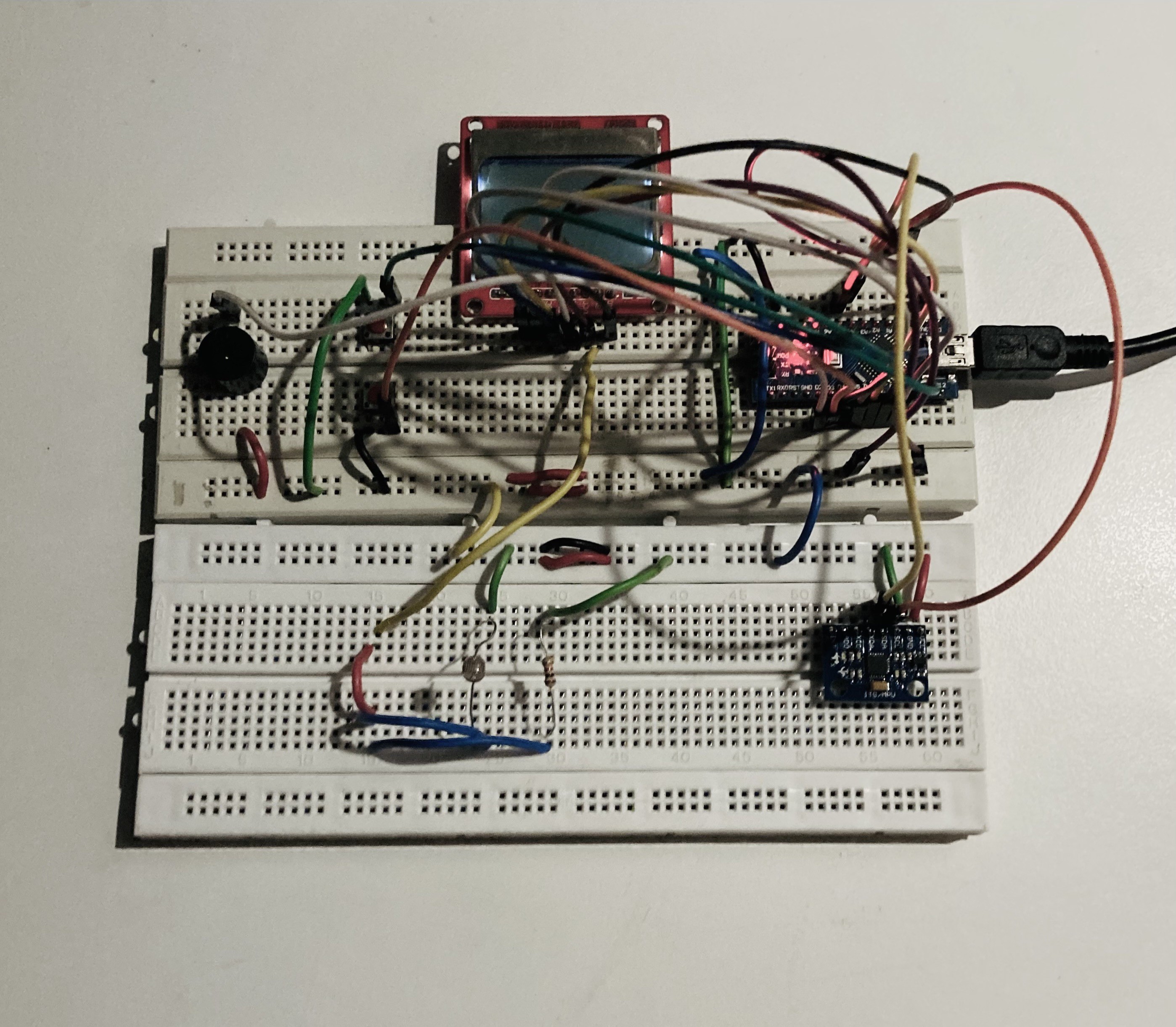
The player can control their character using 2 buttons and a gyro sensor. The gyro sensor is used to move the player horizontally while the 2 buttons are used to move the player up and down. I have also used a buzzer to add sound effects to the game. I have used the arduino nano board as it takes up lesser space and hence makes my game console more compact.
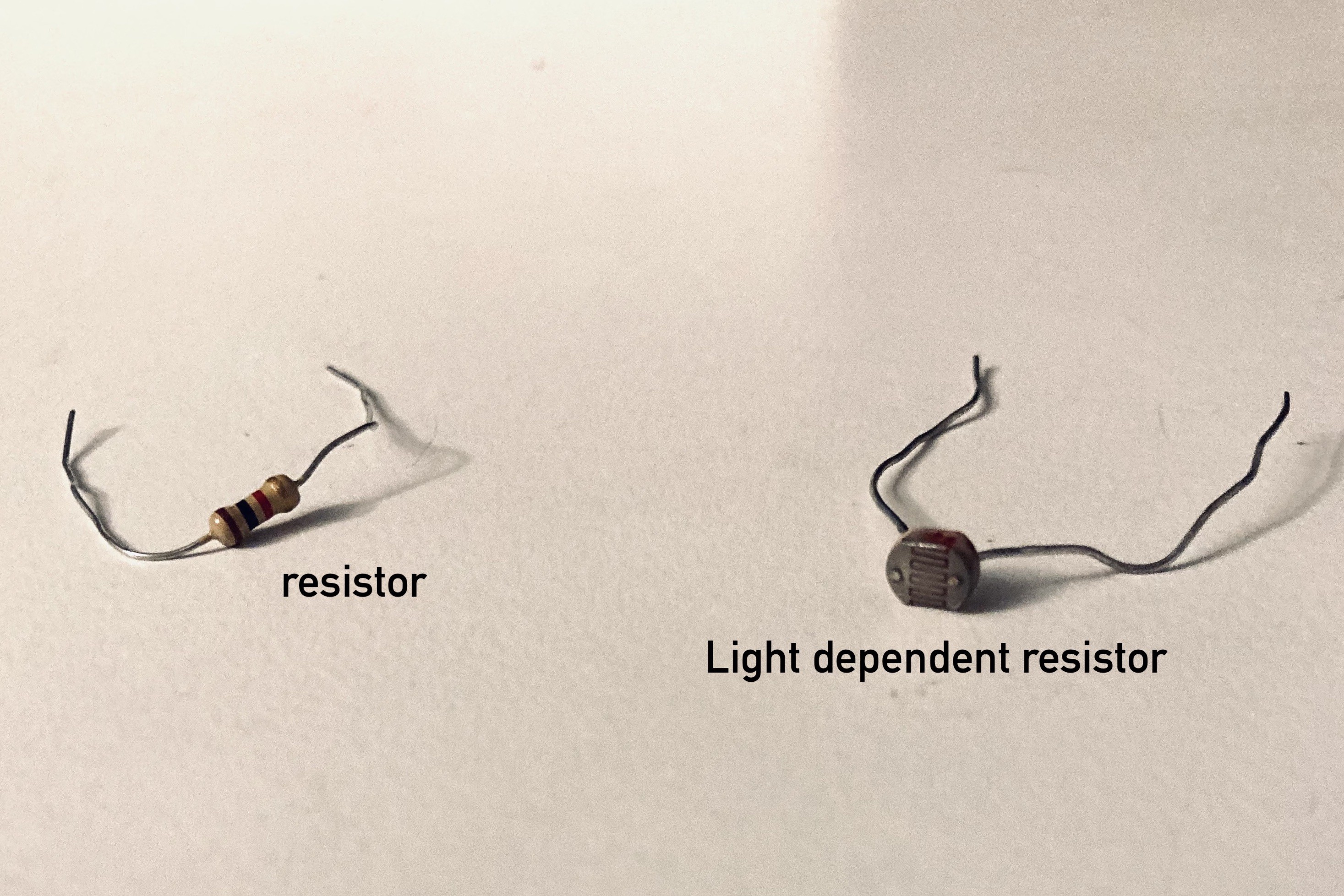
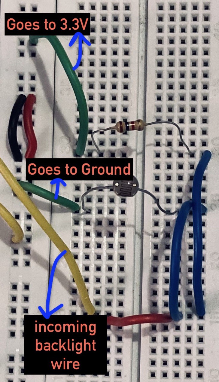
I specifically chose the Nokia 5110 LCD screen for this project because this screen contains back lights. Using a LDR (light dependent resistor) I created an automatic light circuit which alters the light intensity of the back lights based on the surrounding light intensity. When it is in a darker environment, the back lights become brighter while when it is in a brighter environment, the back lights become dimmer.
Finally, instead of directly soldering all the components onto the perf board I soldered female pin headers and then attached these components to these headers. This not only allows me to reuse these components for other projects but it also protects these components from damage while soldering. I did this for the arduino nano board , Nokia 5110 screen and gyro sensor.


 Hulk
Hulk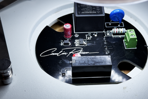
 Cornelius Robinson
 Lithium ION
 Sagar 001