 Mario Ninic
This modification consists of adding small pre-amplifier board to the guitar side of the cable. This modification is intended for long guitar cables (over 10 feet) and if you using active guitar pickup this mod will not be beneficial to you.
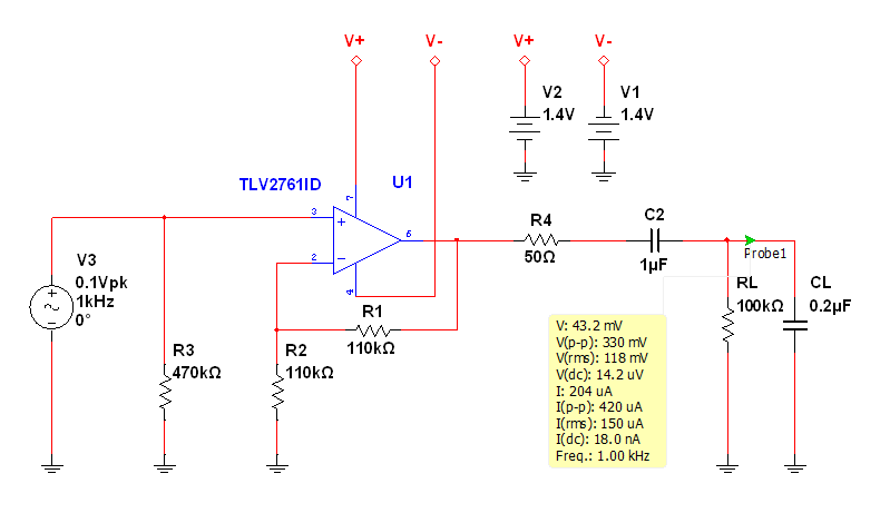
Amplifier specification:
Input Coupling DC
Input Impedance ~500kOhm
Maximum Input Level +2 dBu, <0.1% THD, at 1.4V battery Voltage
Output Coupling AC
Output Impedance 50 Ohm
Max Output Level +2 dBu, 20-20 kHz, 100k ohms, <0.1% THD, at 1.4V battery Voltage
Maximum Gain 2
Frequency Response 20Hz - 20kHz, -0.1, -0.1 dB
THD+N 0.005%, 1kHz at -6dbu, 20kHz BW
Residual Noise 20Hz to 20kHz BW, < -80dBu
Power Requirement Two Zinc-Air batteries, 1.4V, 600mAh
Battery Life Dependent on battery type and usage (3months)
Schematic diagram:
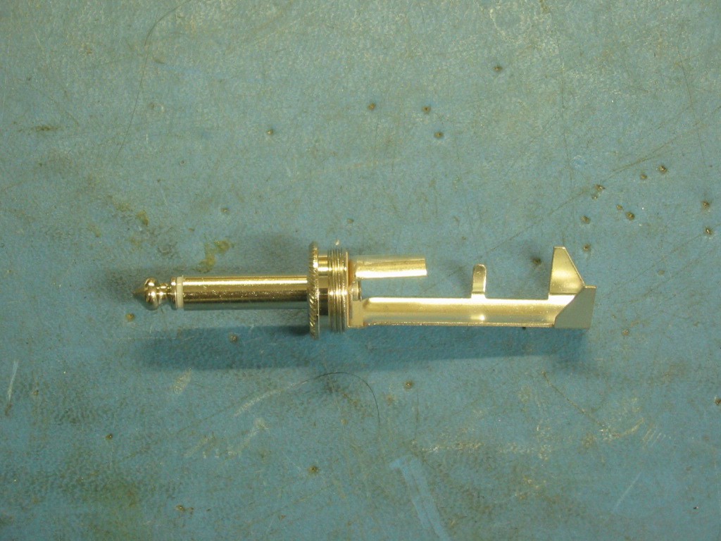
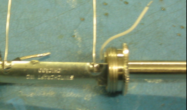
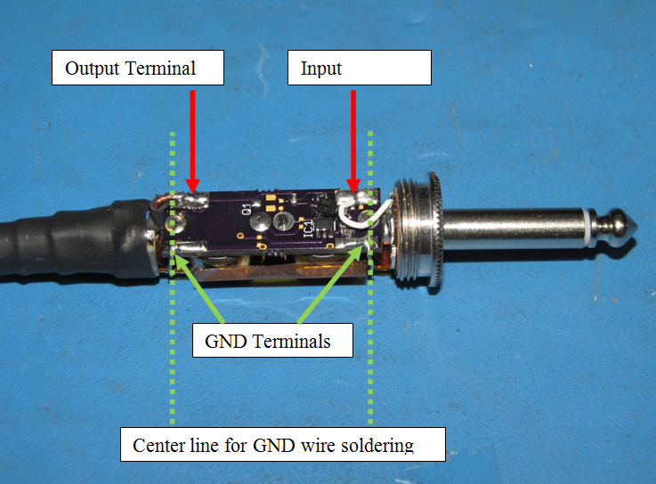
The modification consists of removing ground tab, signal tab and soldering copper tube insert to serve as strain relieve. The connecting wire is added to the center pin to connect signal to the board.
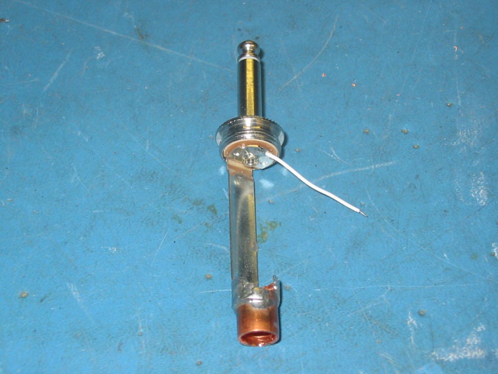
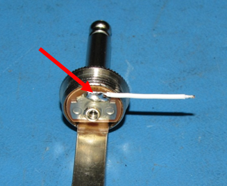
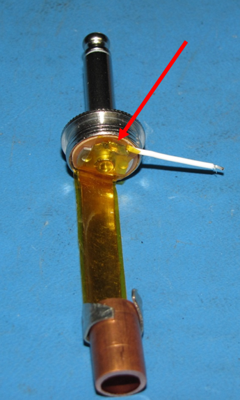
Next, the ground wires are soldered to the body of the plug.
The body of the plug must be insulated using mylar tape, or similar.
Next, prepare cable. Strip cable outer insulation at 1” length and inner insulation to 0.15”.
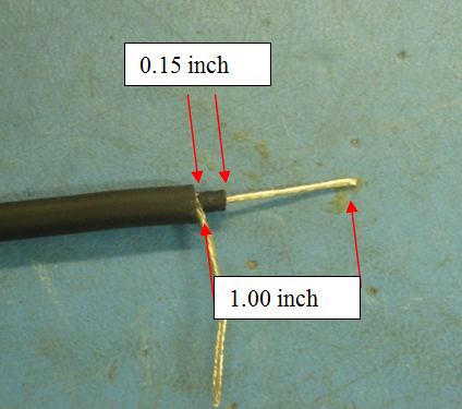
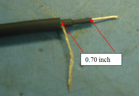
Apply heat shrink tube 0.70” length on the center conductor (1/8” x 0.70”)
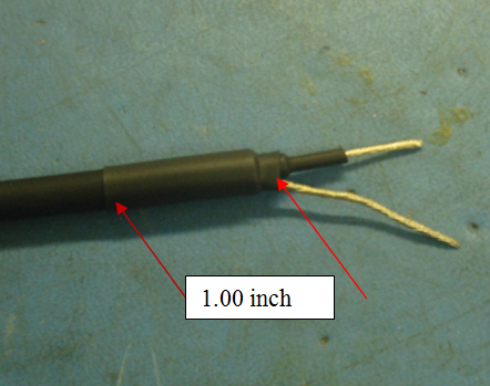
Apply heat shrink tube 1.00” length on the cable (1/4” x 1”).
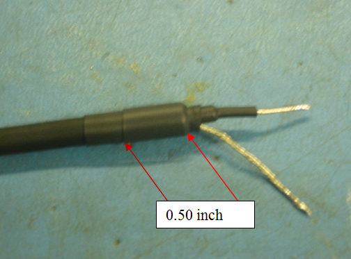
Apply heat shrink tube 0.50” in length on the cable (1/4” x 0.50”).
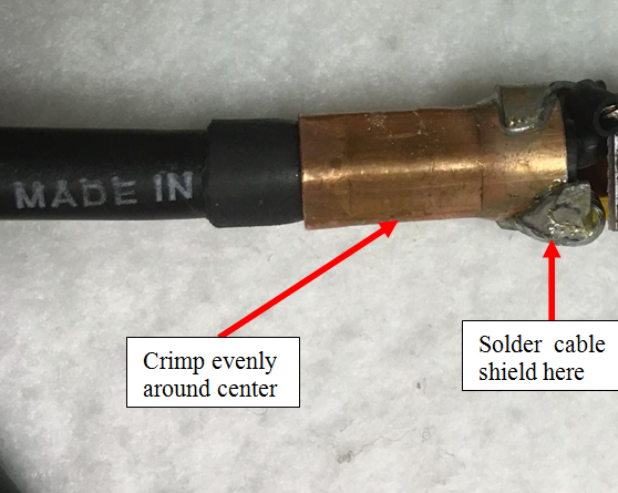
Insert cable into copper insert, solder cable shield wire to the top of the exposed strain relief terminal and crimp the insert using crimping tool. Crimped part should look as round as possible, no sharp edges should be visible after crimping.
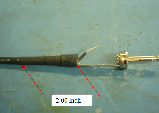
Apply heat shrink tube 2.00” length on the cable (3/8” x 2.00”).
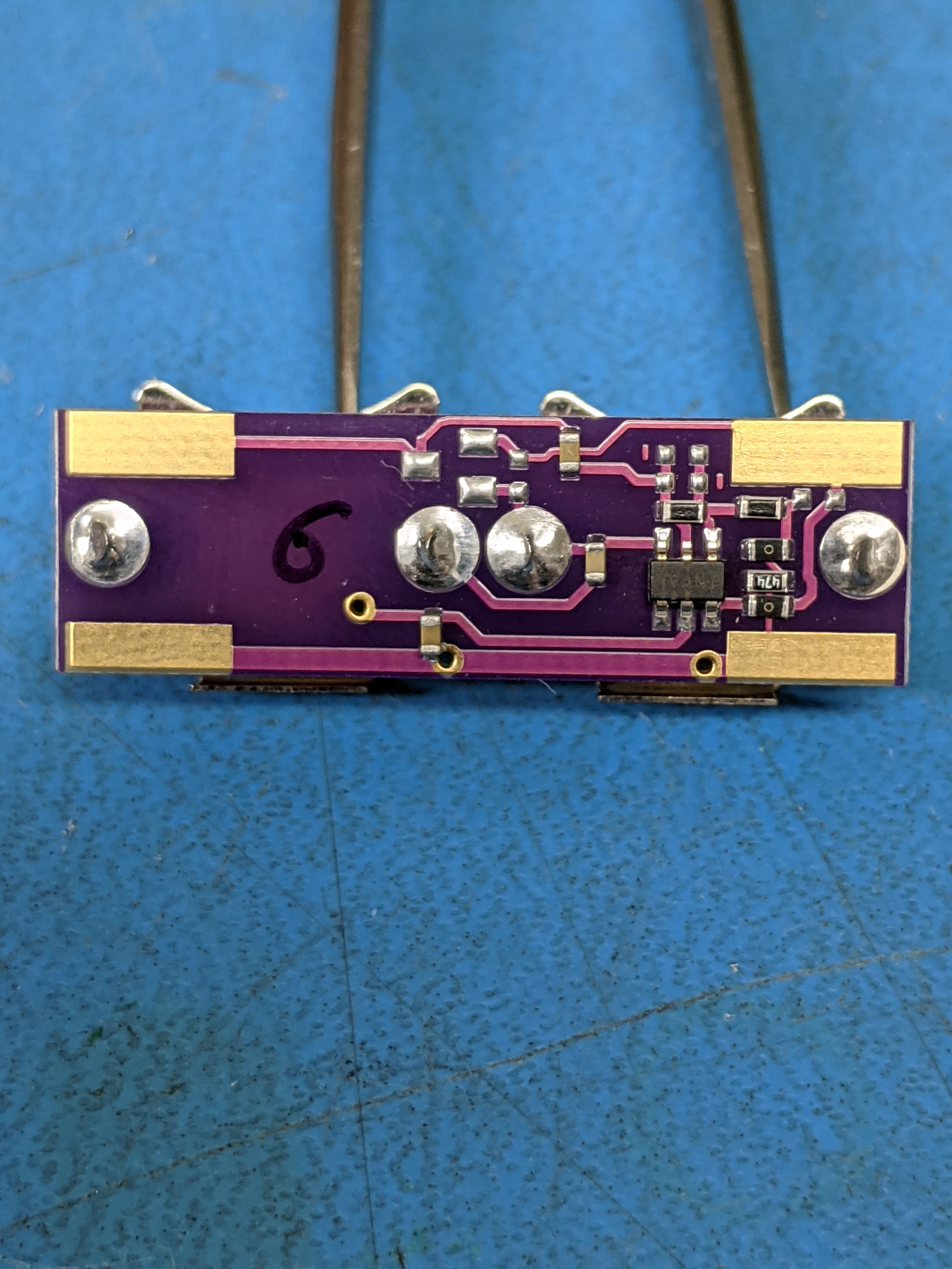
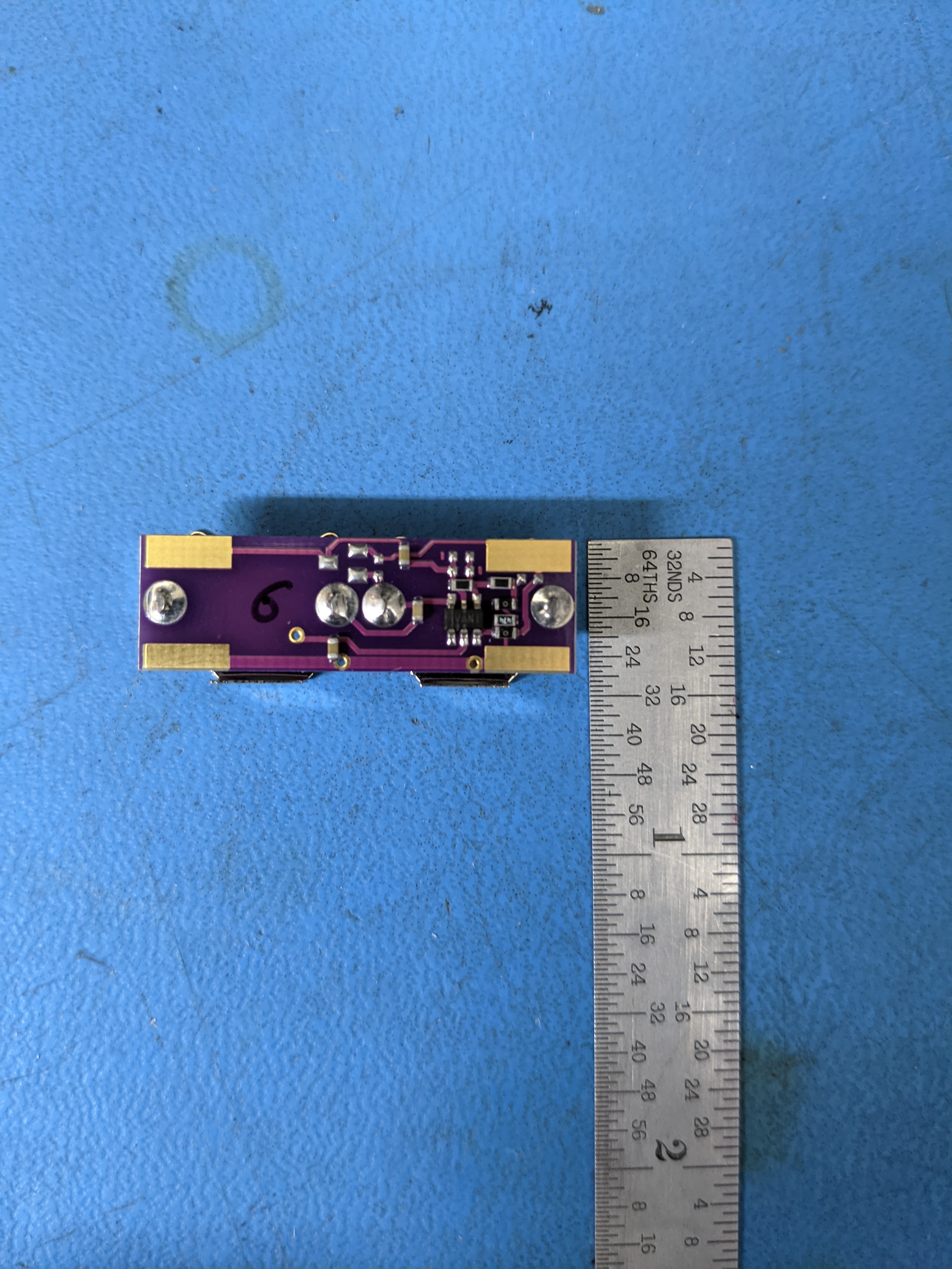
At this point plug is ready for board installation.
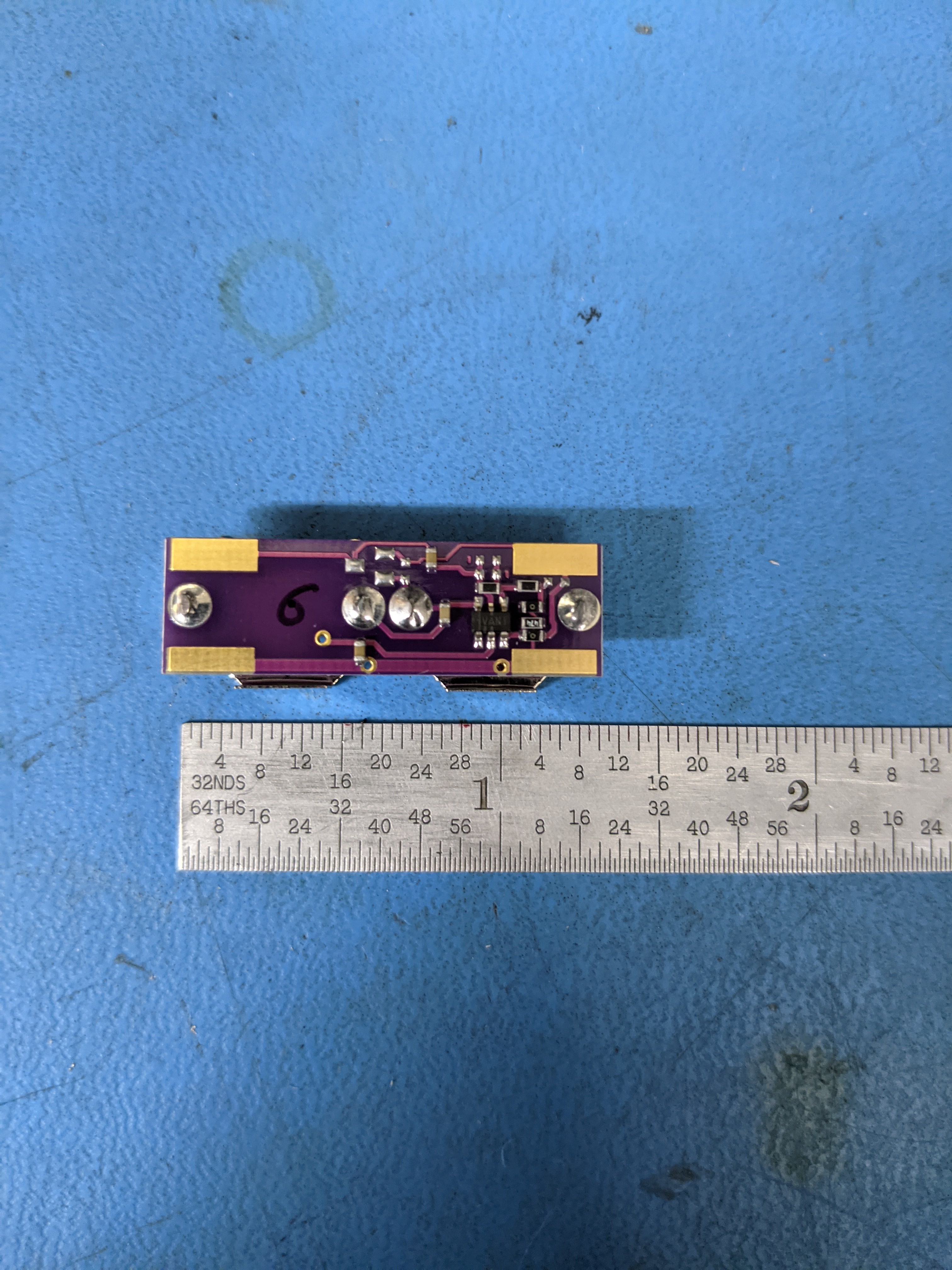
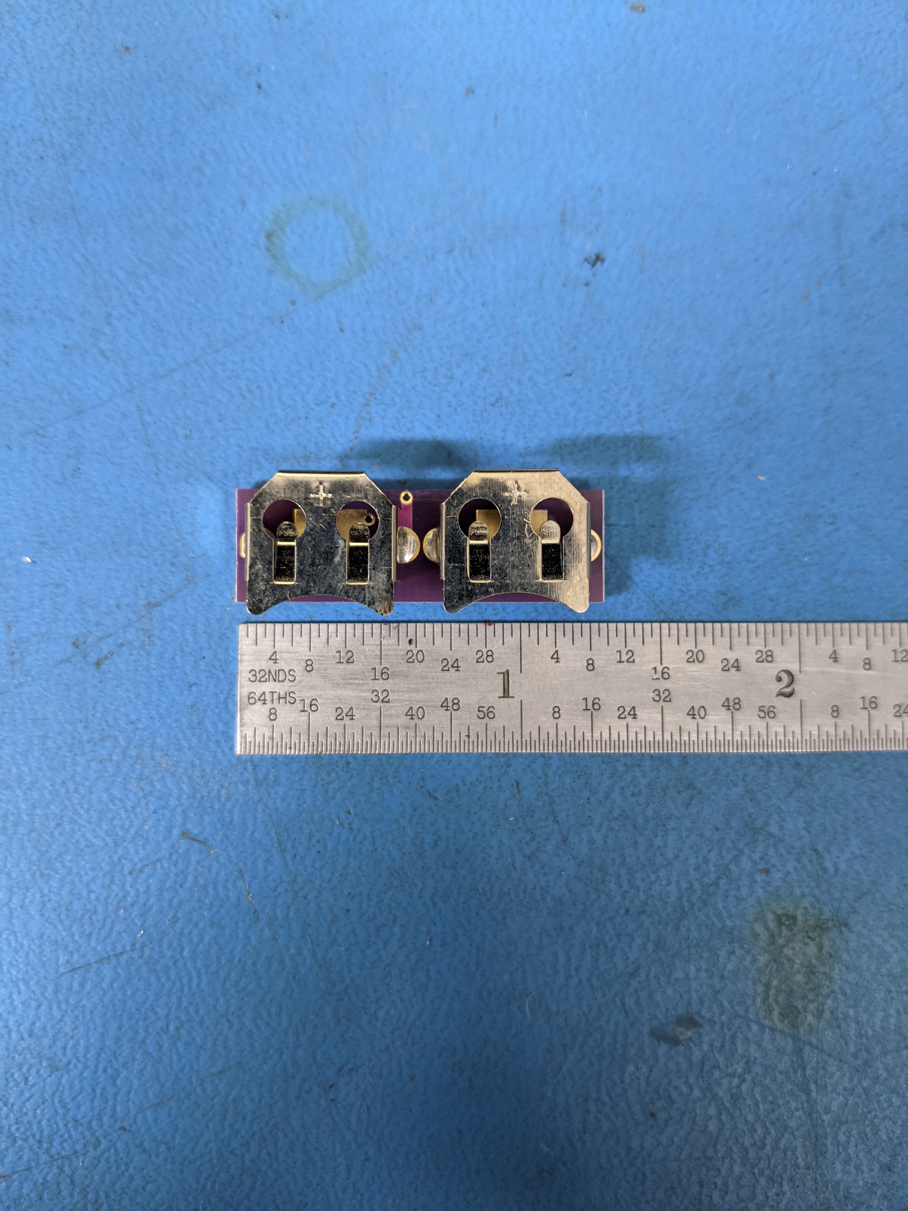
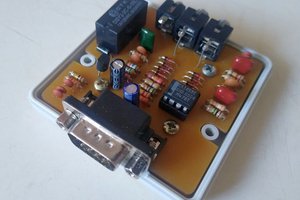
Installed board should fit nicely inside the Switchcraft 188 plug.
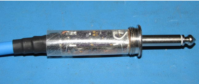
To install batteries, simply insert two 675 Zinc Air or LR44 batteries into the holder and close the plug.
Not sure if I still have board layout files but I have some boards available for sale if anyone is interested.
 Jon
Jon
 Jakob Faltisek
 danjovic