Introduction
The name of DIM-110 came from the Digital Inspection Microscope and the 110 is the work size of the X-Y axes so it is 110mm.
I was into microscope for years now and always wanted a good microscope, but due to the high price and lack of functionality of the microscopes on the used market, I have decided to make one for myself.
I do not want to expain every part of this journey, so if you interrested highly recommend to check out my previous project:
1# Optical scanning microscope
https://hackaday.io/project/166935-optical-scanning-microscope
2# 3D Printed Reflective Microscope
https://hackaday.io/project/176652-3d-printed-reflective-microscope
3# Mobile display reverse engineering
https://hackaday.io/project/179493-mobile-display-reverse-engineering
Before I scare everyone of with this long writing, please watch the short video I made about the machine basic functionality:
Story
I mentioned I wanted a good microscope for myself, but after a lot of try and error I came to a conclusion without good optical components will never have any good result, so I built the reflective microscope. After that I was using it with manual Z axes (with only a screw) and an old plotter base, converted to X-Y stage. I have realised without a good base I will never able to use the microscope for any usefull thing. You quest it I designed one and built the machine base.
This is how you can start with a couple day / week long project and end up with 1-2 year saga.
I do not have to mention, without a good software this machine not capable of any result...
Design
I have used Bosch compatible 2020 and 2040 aluminium profiles for the frame, the reason because easy to work with them and at the end those with the right design can give rigidity. Rigidity is very important factor when we talk about microns, very small amount of vibration or deformation can cause the microscope to become unusable.
It is a bit ridiculous to talk about rigidity when I used 3D printing for almost everything expect the frame. I have used PLA which is fine, PETG or ABS could be a better choice, but I had experience with PLA so I choosed it. I still think with right design it shoud not matter to much.
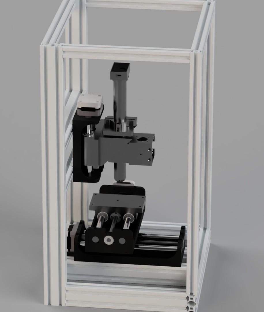
My main point about the axis setup was, I do not wanted to have a moving gantry. Also not wanted to mount the Z axes on top of the Y axes like usually moving gantry machine has. The reason is simly the further the microscope hang from the frame the higher the deformation and the vibration sensitivity.
The ideal type axis setup is Y axis is on top of the X axis and the microscope mounted only to the Z axes. This may not be the best option for every circumstance, but inmy case when the sample which I want to inspect is a few tens of grams maximum that will not cause deformation for sure. One down side for this setup is the frame have to be bigger than a gantry setup machine.
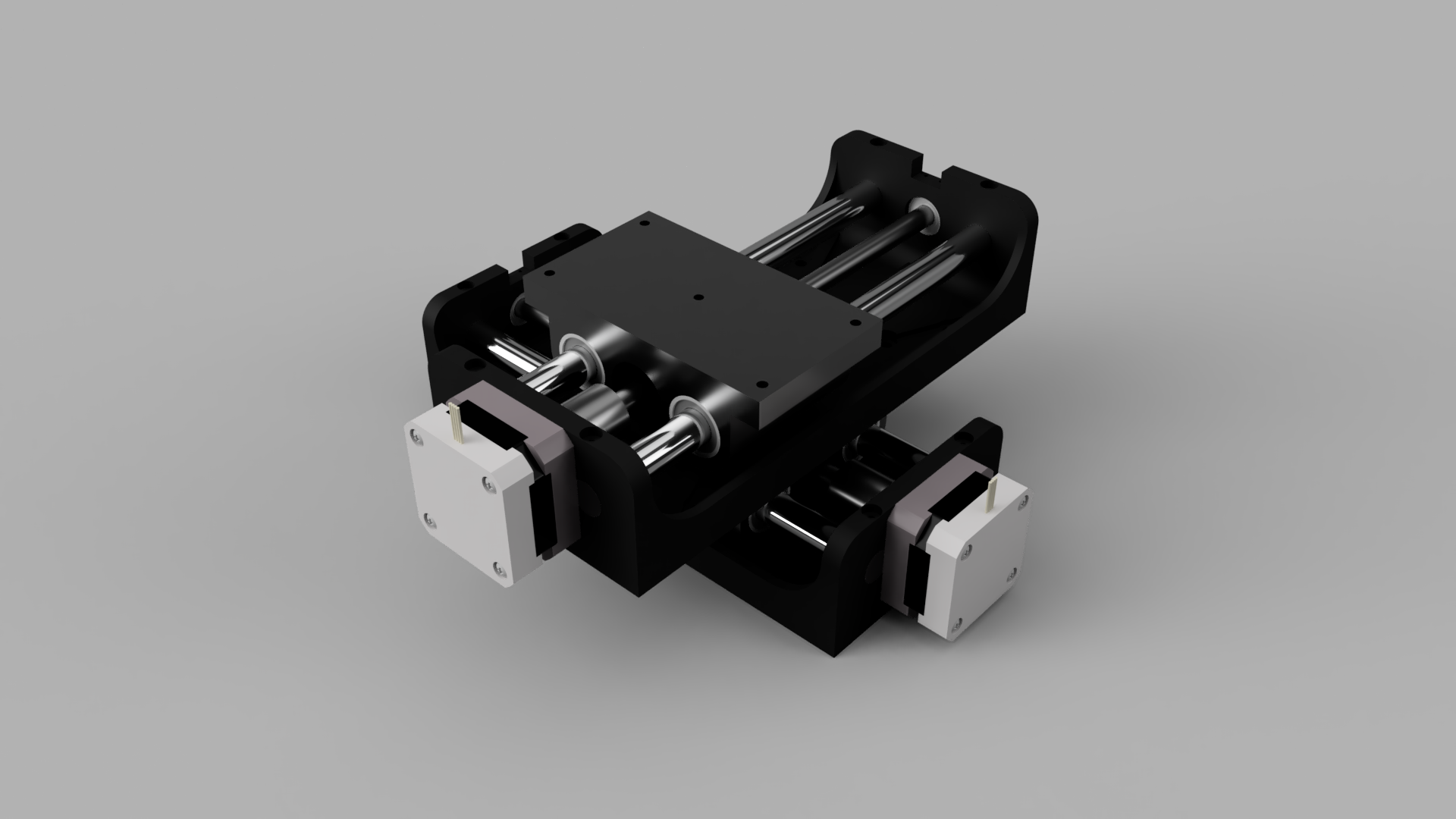
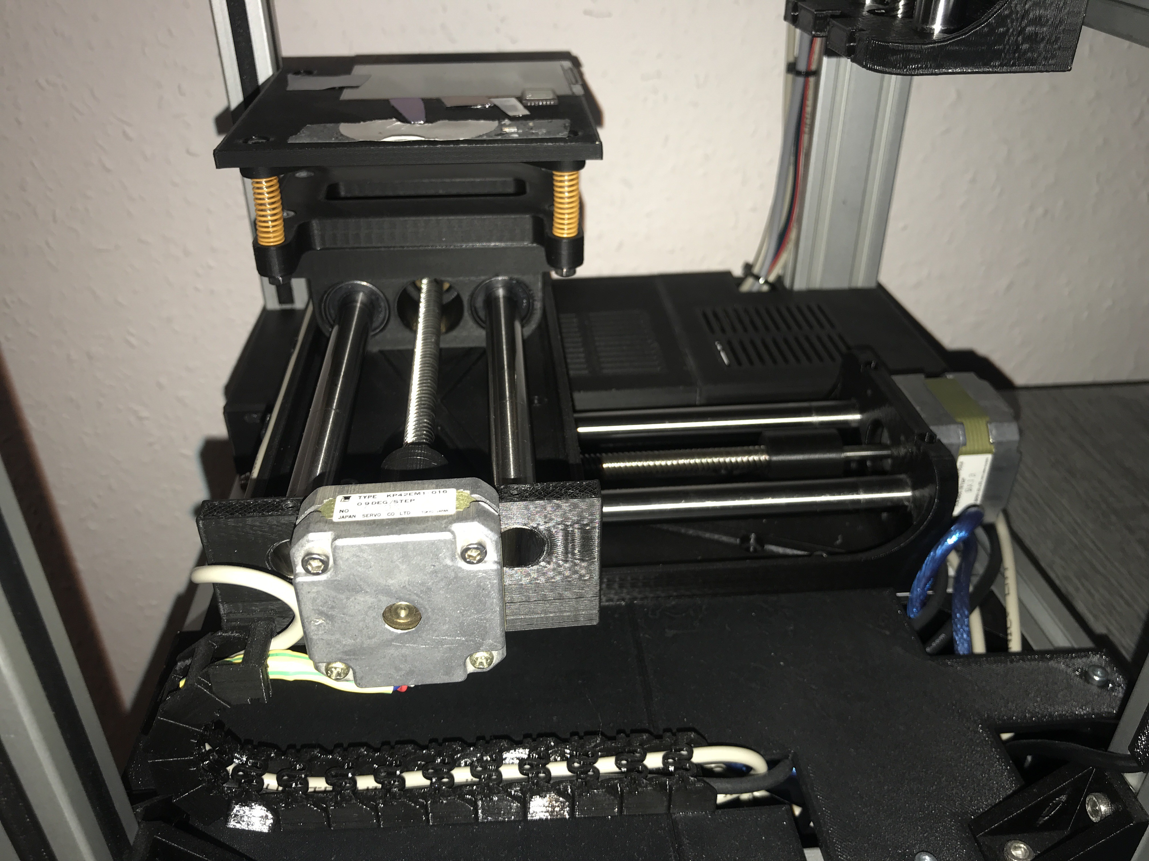
I have designed the axis only once and made it compatible to assambly an identical one perpendicular to it on top. The axis have a PLA base frame with 30% infill and two 12mm linear rod press fitted into it, this made the PLA frame quite rigid. For the motors I use some used 0.9 degree stepper motors with 8mm threaded trapezoidal rods (sadly I could not find local 2mm trepezoidal rods).
The carriage also printed in PLA and press fitted the 12mm long linear bearings. Made place for the anti-backlash nuts which are cheap chineese one, it is hard to call them anti-backlash when it manufactured so cheap it has +-100micron backlash...
The Z axis design is the same just shortened.
On the below two image you can see the X-Y axis and the whole machine rough design render:
The stage is also 3D printed, I have made it levelable with simmilar solution as 3D printers use for bed. There are 4 screws with springs ont he for corner of the stage and from up it can be leveled with allen key.
Building
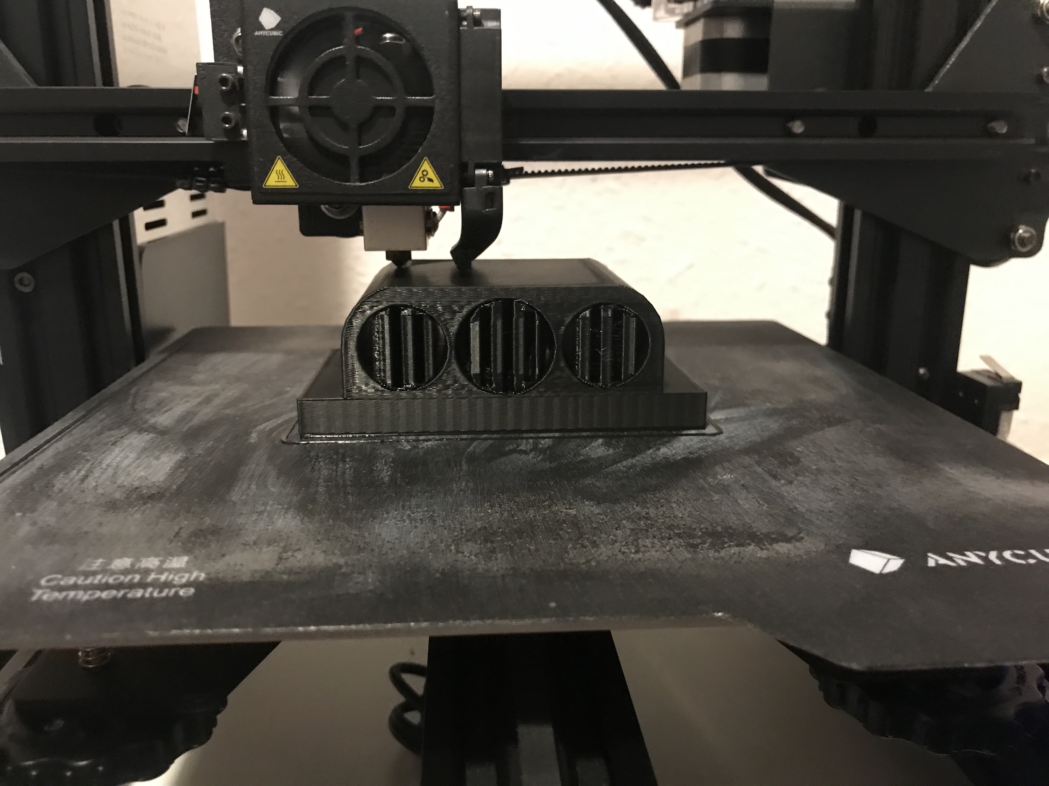
I have used ~1,5 Kg PLA to print everything for this machine. It was not easy to print the bigger parts especially the 3 axis parts, those and my cheap Anycuboc mega zero 2.0 gave me very hard times. At the end it came out "ok" some part was later find not compatible and had to go back to the drawing board.
I am not joking when I say I used PLA for almost everything I could, all the aluminium profile triangle brackets are PLA and even the motor coupling PLA.
Some picture about the process:
Z asis below, later found out the flexible motor coupler is not ideal because of flexing :D (later printed a solid coupler)

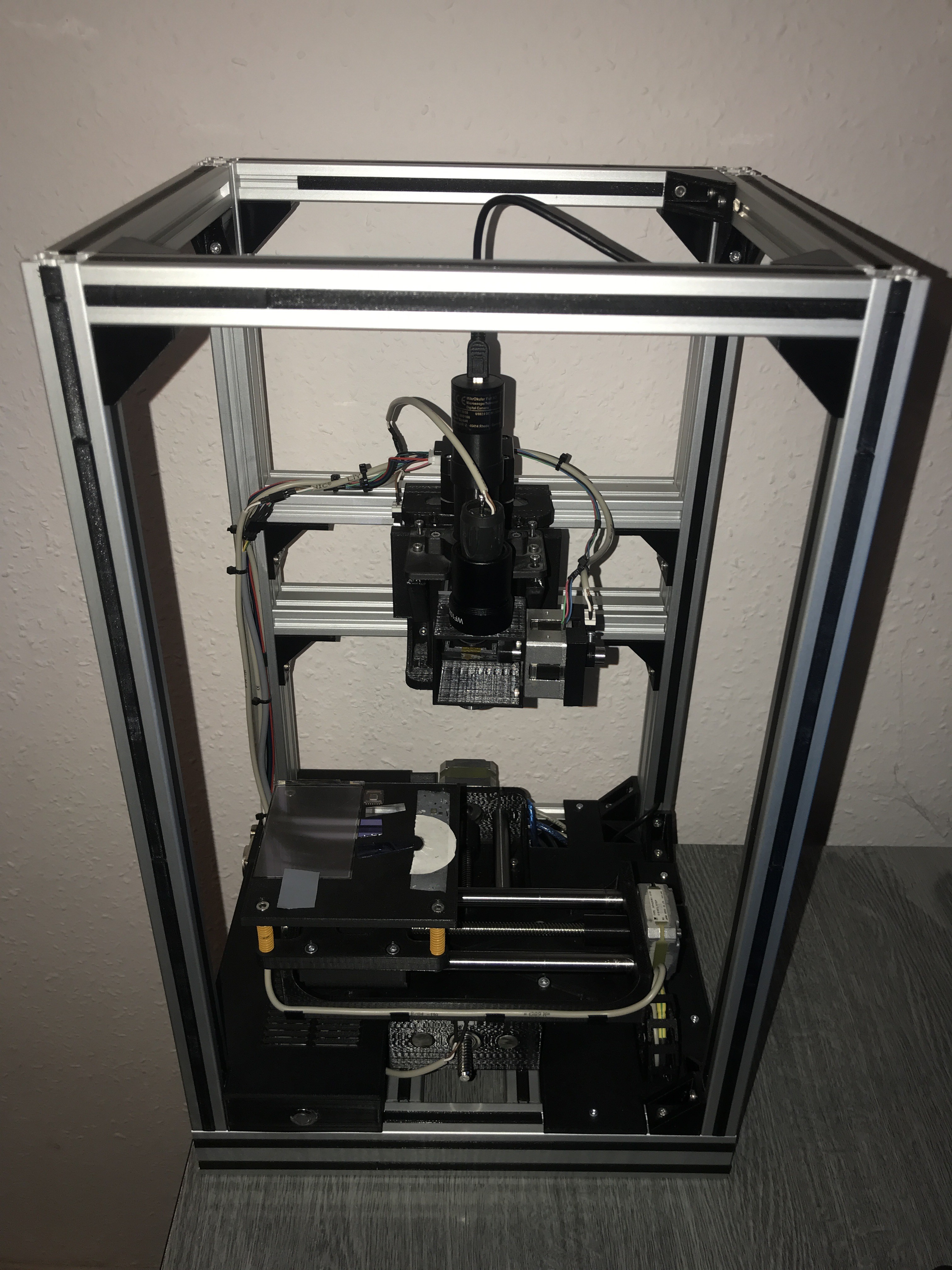
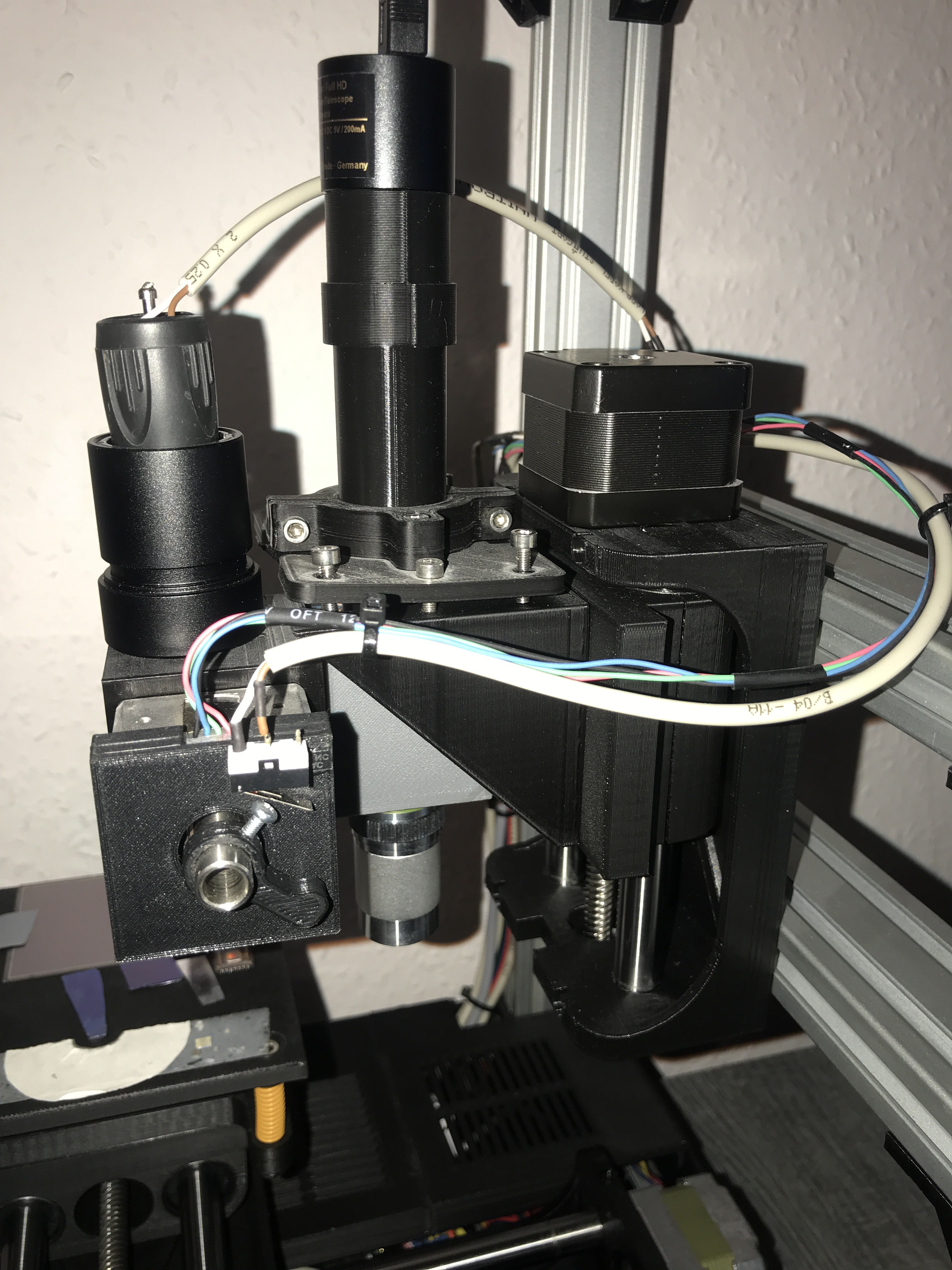
On below pictures you will see the finnished product, which still missing some 2020 frame covers. (I would like to redesign the microscope head that is still not the finnished)
From mechanical point of view I am quite happy with the result. This is my first documented fully built machine.
Electonic components
At the moment this machine has 4 axis three for the movement and one is on the head which moving the grating for wavelength selection. Later I would like to add a lower megnification objective (4x) and for that will later add an motorised objective changer.
In this in my mind I built the electronic to compatible up to 6 axises. I reached this with two CNC shield V3 with two arduino uno.
The electronic need to go somewhere so I used bot sides next to the X-Y axis inside the frame. The left frame contains the two CNC Shield V3 (movement). On this side mounted the DC 12-24V socket connector and the USB B connector.
The right frame has an USB hub so only one USB have to leave the machine and the two Arduino Uno plus the USB camera can connect to this hub.
I have tried to hide as much cabels as I can so the looks of the machine more like a product, not a prototype.
Some pictures about the current state of the machine:
On the below picture you can see the stage leveling mechanic, four screw with orange springs.

Cabels are commung up to the Y axis in chain.
Full HD USB camera used for the imaging.
For better position stability I used one end stop which the used for homeing the axises.
What I inspect
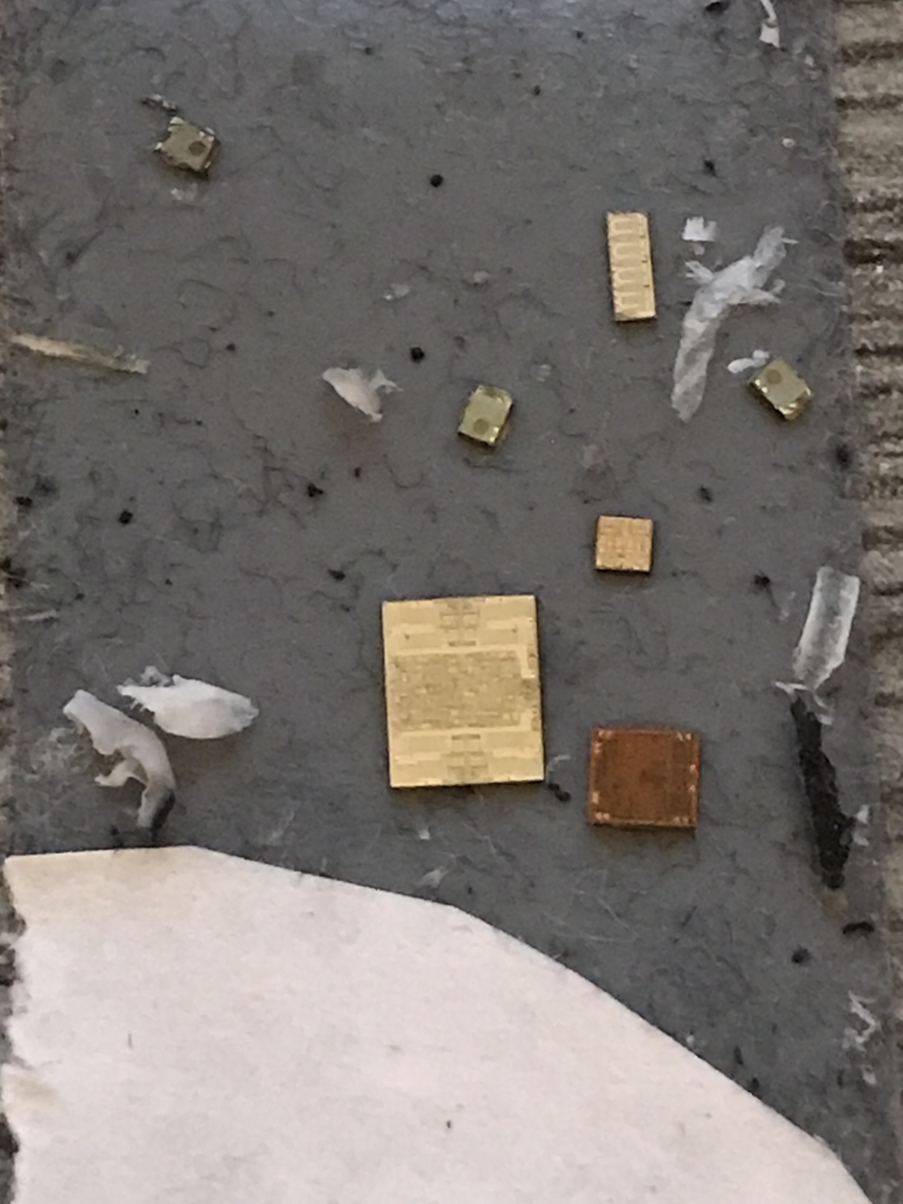
I would like to inspect and study microscopic electronic like display circuits IC die structures and everything what is related to electronic.
At the moment I have displays (Iphone, Samsung) , IC dies from opened some mostly analog IC-s and an old camera CCD. The allen key is there for comparison of size. (2,5 metric allen key)

This CCD came from an old intercom. It is so old even packaged to this weird format. On the die on the right and up side has the driving electronic as you will may see later. On the middle is the active sensor area.

My software now can do basic functional control of the machine so I made couple of pictures of every sample.
You can see probalby the type number etched onto the CCD die. (if you want to orient the below picture where was it taken on above picture, it is in the top left corner of the die)

Below picture shows the top right active area edge of the die.
These are IC die -s, these are the heart of any IC which packaged with that bulky DIP package mostly. On right bottom there is an PIC microcontroller die, next to it some kind of analig IC die. Above these the longer die is an ULN IC die. Next the three little die are opto coupler IC die-s, the black circle is the sensor area.
This below picture was taked with my phone camera (5X magnification)
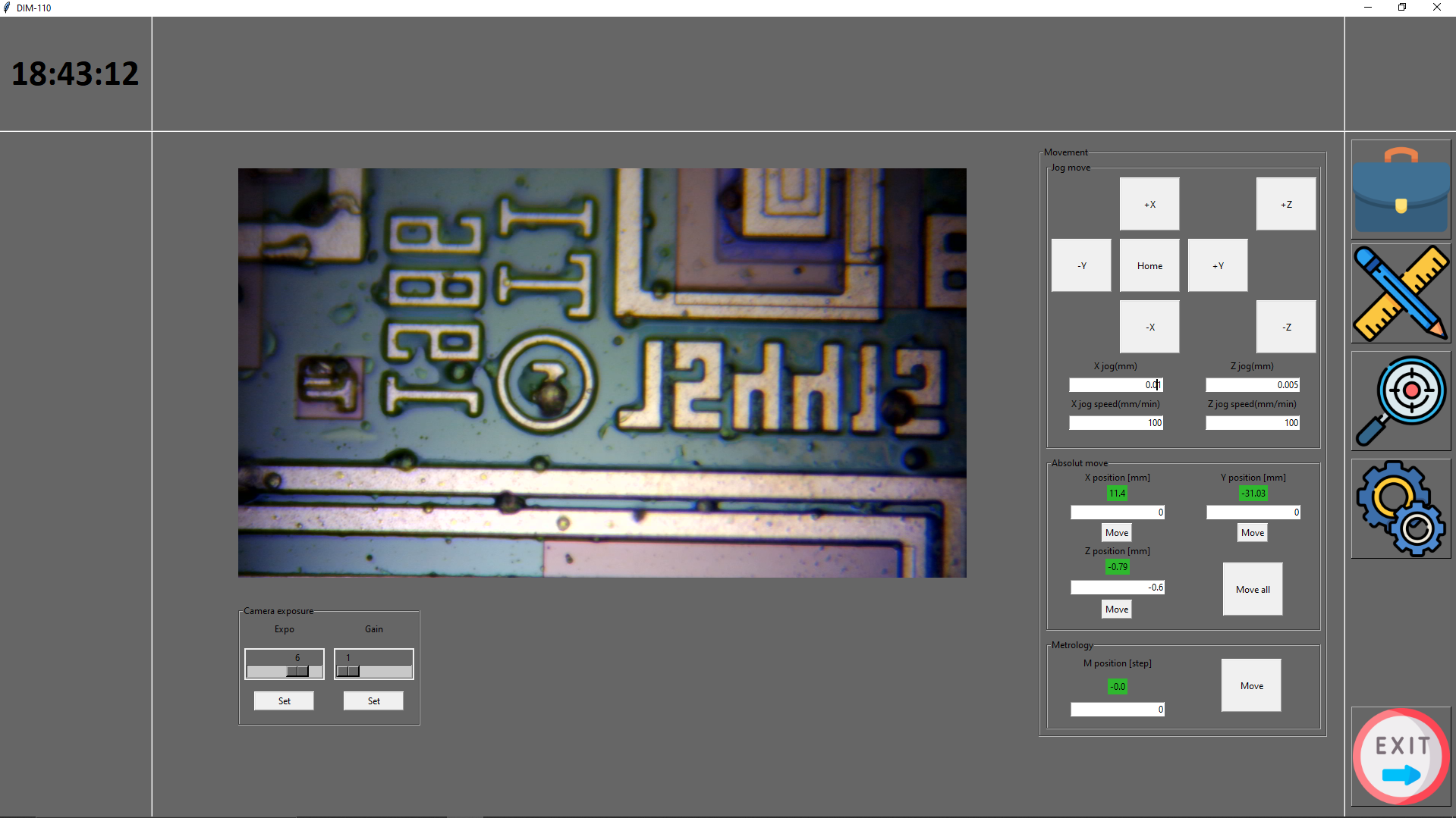
The biggest die under microscope you can see below, it is an Texas Istruments IC. It was designed in 1986
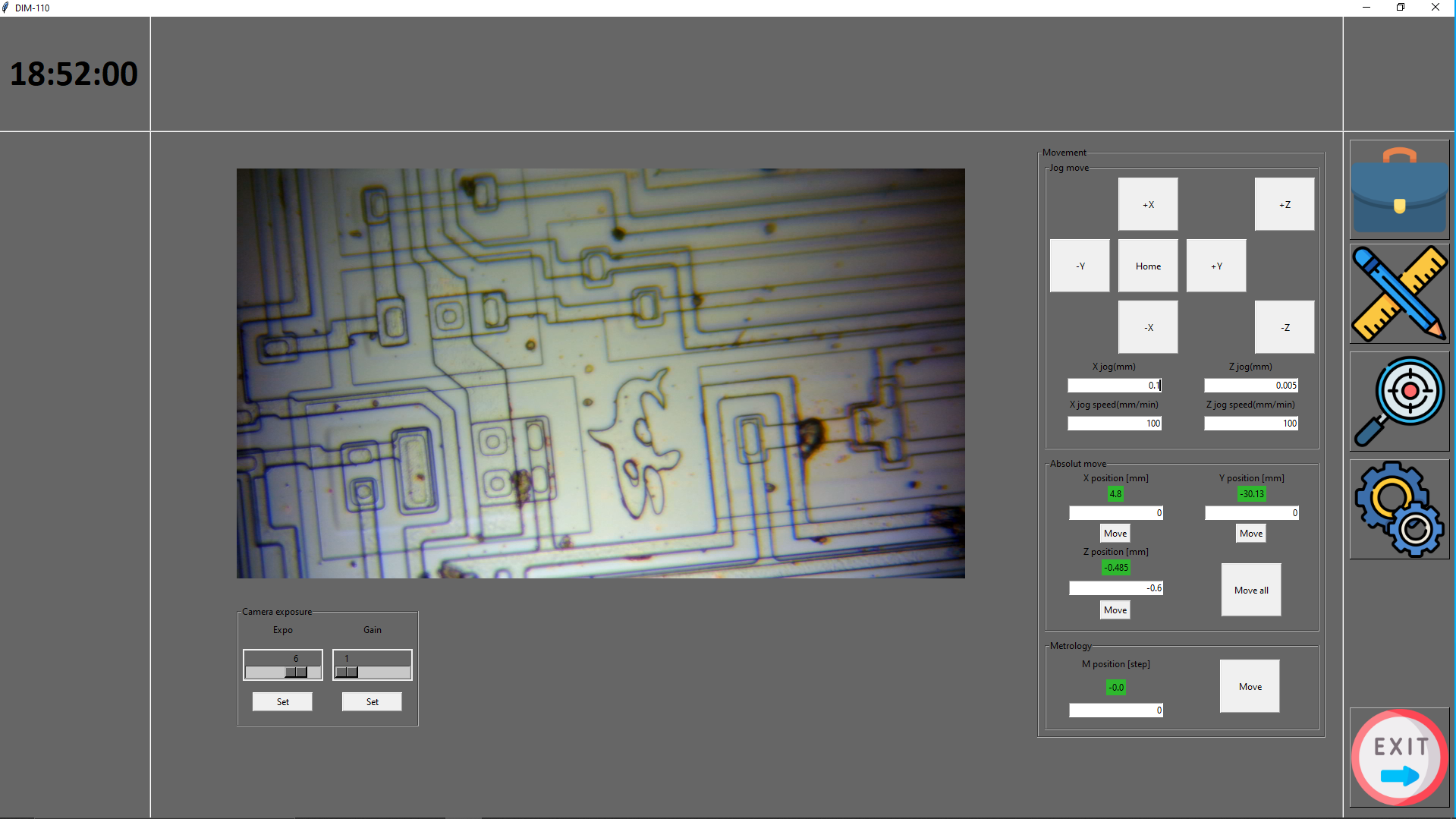
The below picture shows the PIC microcontroller die on this in the side you can see the Microchip text and logo.
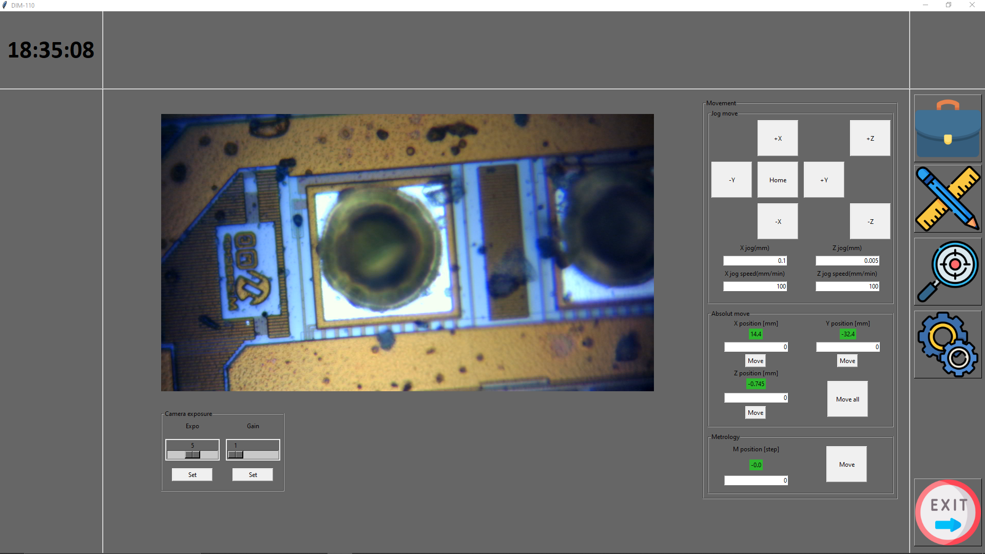
One of the opto coupler die picture below it has a whale on it.
The basic idea not only would be just take one picture of the die, rather take several hundred pictures and stich them together to get the whole die image instead with high resolution. I wrote a demo for my software where it scanes the die step by step and take an image every step. On the end I have got several hundred images and stiched them togehter with Microsoft ICE.
You can see the result below, it is the ULN chip first 1/3. (Image uploaded here have to be scaled down due to the 5MB limit so you can not see the details I recorded it)

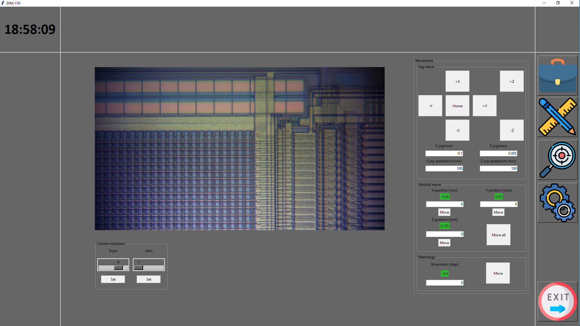
Software
The software is a very important part of this project as it have to controll the machine. I am not a programmer so it was a big chalange for me. I knew Python and openCV so I could start the software, but had no idea before how to program in object oriented form and use UI elements.
This was the project which forced me to learn and dig down into python. Python may not be the best choise, but I would not wanted to start from the beginning with a new language.
My main goal was to be able to controll all of the axises from software and be able to see the camera image.
At the moment the software able to do the above things with some plus functions as settable camera exposure setting and automatic image focusing (Laplace image focusing).
In the future I want to imlement:
- scanning which generate the images which after I can separately stich together.
- automatic image capture on pre saved coordinates (multiple points)
- wavelength scanning on pre saved coordinates.
- automatic recipe measurement function for image capture and wavelegth scanning.
Further developments in project logs.