Jithin Sanal
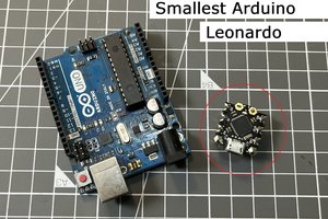
In this project, we are going to be making our own customized Arduino Uno board and I will be showing you how easy it is to make one. I will be explaining everything in detail, in very simple terms so that it will be very easy for you to understand. Everything you need to build your Arduino board is in the description. Make sure you check it out! Let’s get started.
How to make an Arduino Board – Video Tutorial?
Too lazy to read? we have a complete video tutorial for you! Push the play button below, sit back and enjoy!
Components needed to make Arduino Board
- ATMega328
- 16 MHz Crystal Oscillator
- Capacitors
- Resistors
- LED
- Header pins
- FTDI Programmer
- Connecting Cables
DIY Arduino UNO – Circuit
Bare minimum configuration
In order to make our Arduino board, we will need a microcontroller, which will be the one doing all the mathematical calculations and doing all the logical decisions. So which microcontroller do we use in our Arduino Board? Here, will be using an ATMega328. The microcontroller can’t operate without the bare essentials. In order to function, it just needs a minimal amount of setup. Let’s look at the bare minimum configuration.
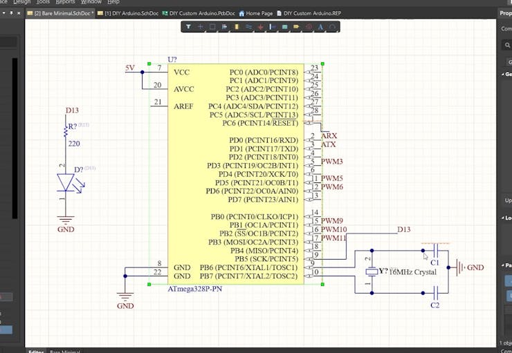
I used an Altium designer to draw the circuit and design the PCB. It is a powerful tool that can be used to design and create your own PCBs for your project as well as complex and multiplayer PCBs for industrial use. I will leave the link to the free trial version in the description. I have been using it for the past 3 years. If you are an electronic engineer, it’s gonna be really useful for you. Also, if you are a student, you will get 6 months license completely free of charge! So do make use of it!
To get started with the bare minimum configuration, we will need the ATMega328 chip, 16 MHz crystal oscillator, and two capacitors. Crystal Oscillator will be connected between pins 9 and 10 and the two ends are connected to the ground. Why do we need a crystal oscillator? Every microcontroller needs a clock signal and every action inside the chip is based on the clock. For the Arduino, clock signals are provided by a Crystal oscillator.
Once you power up the ATMega328, it will work. But that is not enough, is it? We will be making it more stable, versatile, and more USEFUL. Let’s make it closer to the real Arduino Board.
Making a Custom Arduino Board
This is the point where we will be connecting the input voltage. Input power will be connected to a 7805 voltage regulator which will convert a voltage between 7-32 volt to a steady 5V DC Supply, which will be fed to Arduino and other components.
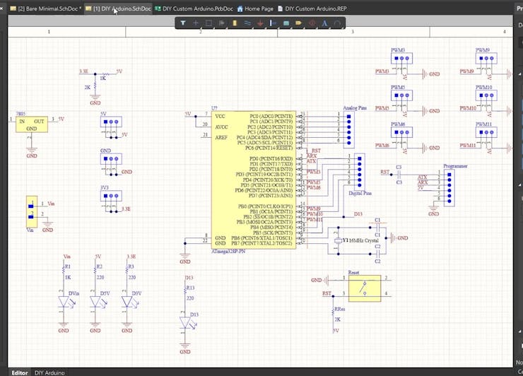
This 5V is also fed to a voltage divider circuit which will reduce the voltage to a 3.3V DC voltage. This will be really helpful when we are connecting modern sensors and modules as most of them work on 3.3V.
PWM pins are connected to these 3 pin headers, where the first pin is connected to corresponding PWM pins, the second pin is connected to 5V and the third pin is connected to GND. This is the pin configuration of most of the servo motors and sensor modules; which means, you can connect your Servo motor directly to this Arduino Board.
Then here are the Analog pin headers, which are connected to the Analog Pins, and here are the digital pin headers that are connected to the remaining digital pins.
And we have some indicator LEDs that will help us to troubleshoot if anything goes wrong. This LED is connected to Pin 13 of the ATMega328.
Now the real question is how do we program this Arduino Board? The ATMega328P chip can’t communicate with USB directly. Their way of communication is UART.
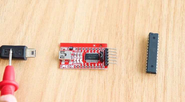
So in order to program the Atmega328 using USB, UART data from the chip is sent to another module that can convert UART to USB and vice versa, which will bridge the two technologies together. In our case, we will be using an FTDI module that will handle the communication between ATMega328 and our computer. This is where we will be connecting the FTDI module. The Tx pin...
Read more »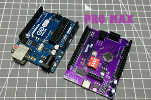
 Lithium ION
 icstation