 zapwizard
Build video:
Animations:
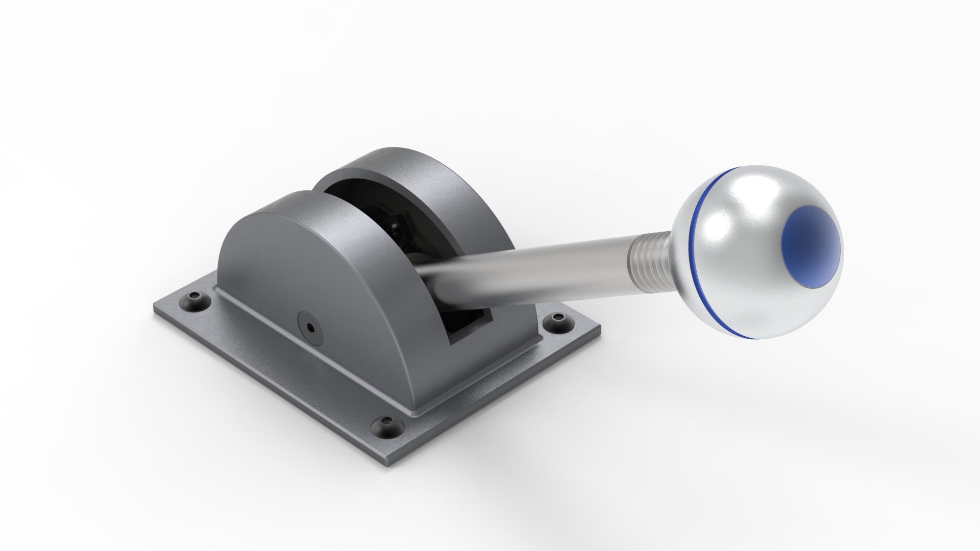
A functional and faithful recreation of that control lever that Grogu was so interested in.
Already have an account? Log in.
To make the experience fit your profile, pick a username and tell us what interests you.
It is done! I will have a video showing the whole build coming soon. I ran into a bunch of stupid issues that I had to work through as I built. So you get to learn from my mistakes ahead of time.
My favorite thing is that the whole prop looks like it is made from solid metal. The prop is also heavy! It weighs 0.64 kg or 1.42 lbs. The aluminum tape method worked well .However it was quite tricky and tedious. I had to do re-apply it a few times to get the exact look that I wanted.
The USB Joystick function works great, nice and smooth once properly calibrated. The pins on the PCB are exposed on the bottom side. So if someone wants to add this design to a functional Razor Crest cockpit mock-up, you can wire in a few other switches to the spare pins.
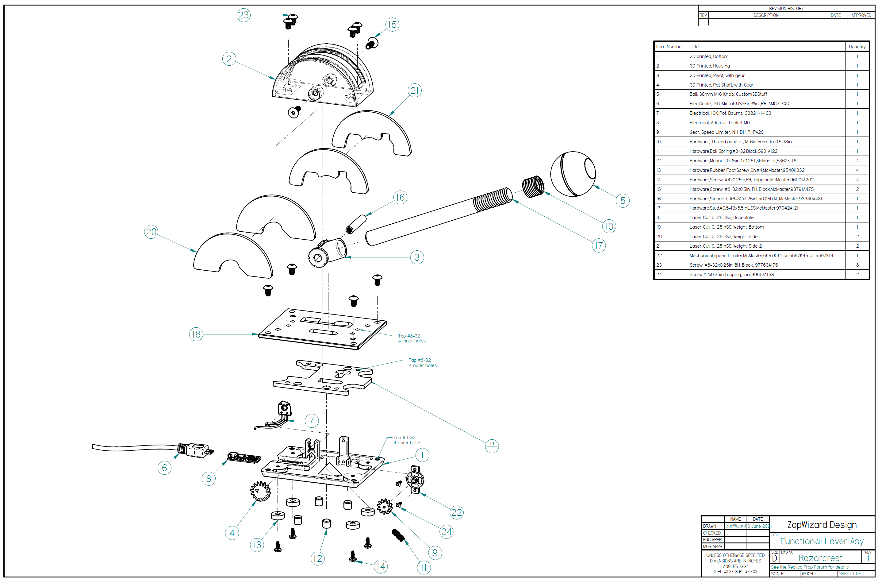
My design is released as Attribution-NonCommercial-ShareAlike (CC BY-NC-SA) similar to E Williams original on this thread. The design files are on Google Drive, and the BOM is on Google Sheets.
If your interested here are the issues I ran into during the build:
Another short test. I took one of my FDM 3D prints and applied aluminum tape to the outside surfaces. The resulting part doesn't look 3D printed at all, or even like plastic, it is even cold to the touch.
I then did a chemical blackening and weathering pass. It is much more aged than what is on the TV show, so I might try again but only use acrylic paint to darken the aluminum.
A small update: I have made some parts on the Fuse 1 3D printer, as they come out a dark grey and with less layer lines than Shapeways. It is almost useable as-is, but I still plan on coating the surface with a layer of aluminum tape for a real metal look.
It took a month, but Shapeways finally delivered my 3D printed parts. There were delays due to both Texas being an ice cube for a week, and Shapeways using the slowest postal method known to man.
I had to grind away a bit of metal on two of the internal plates, but everything otherwise fit perfectly.
The sides have to be pretty tight to get the heavy lever arm to not fall on its own, but it does work. The unit doesn't tip over either, but if I were to use it on a game system I would use the magnets or bolt it down anyways.
I plan on dying all the nylon parts black, and then facing the outside with aluminum tape and polishing that to get a real metal finish.
That won't happen for a bit, as I have Jedi Training Remote Stands to build up and ship out.
I printed up the design as shown earlier. The new detent mechanism works pretty well, and is easier to dial in.
The potentiometer holder and gearing also works.
However, I decided that since I will be making the final 3D printed parts on Shapeways, I shouldn't limit my geometry to what an FDM machine can do. It can still be made on one, but will require a bit of extra cleanup.
One thing that was still bothering me was the center of mass sitting right over the feet, meaning almost any extra force on the lever will cause it to top over. So I added mass wherever possible in the way of four 1/8" steel ballast plates. These will sit on the inside of the housing. That way it is far less likely to tip over even in use. Plus it still has the magnets to provide a few pounds of force if placed on a steel surface.
Okay, so the lever grew a tail...
After playing with the physical object for a bit, I decided it wouldn't be good enough for it to just have some wires coming to some external circuit. This thing needs to be a self-contained USB throttle!
Adafruit makes a tiny Arduino board I have used on a few projects, and their new Trinket M0 should allow this to become a stand-alone device.
I also re-designed almost every aspect of the device.
I added a 3D printed base which will house the PCB, as well as the potentiometer and a sheet of steel to add weight. The plan is to order the ballast and baseplate in stainless steel from sendcutsend.com. Both cause real materials are better, and this things needs the weight.
Screw on rubber feet will prevent it from moving around too much. I have simulated the center of mass, and it shouldn't over tip on it's own. It can still be screwed down if needed. I did look at using lead shot, but it actually didn't change the center of mass by more than 1/8".
For the detent, I decided to laser-cut a ring which will go on the opposite side from the gear. By laser cutting it I can tweak the detent depth to get just the right feel. I could also even add things like small bumps that make the lever feel like it is ratcheting up/down.
I'll mock up this design in the next week, and I don't have to order any more expensive shipping items from McMaster to build it.
I received the hardware today and 3D printed and laser cut the parts. I realized the layer lines would look better it if were printed on its side, so I will tweak the design to work better in that orientation.
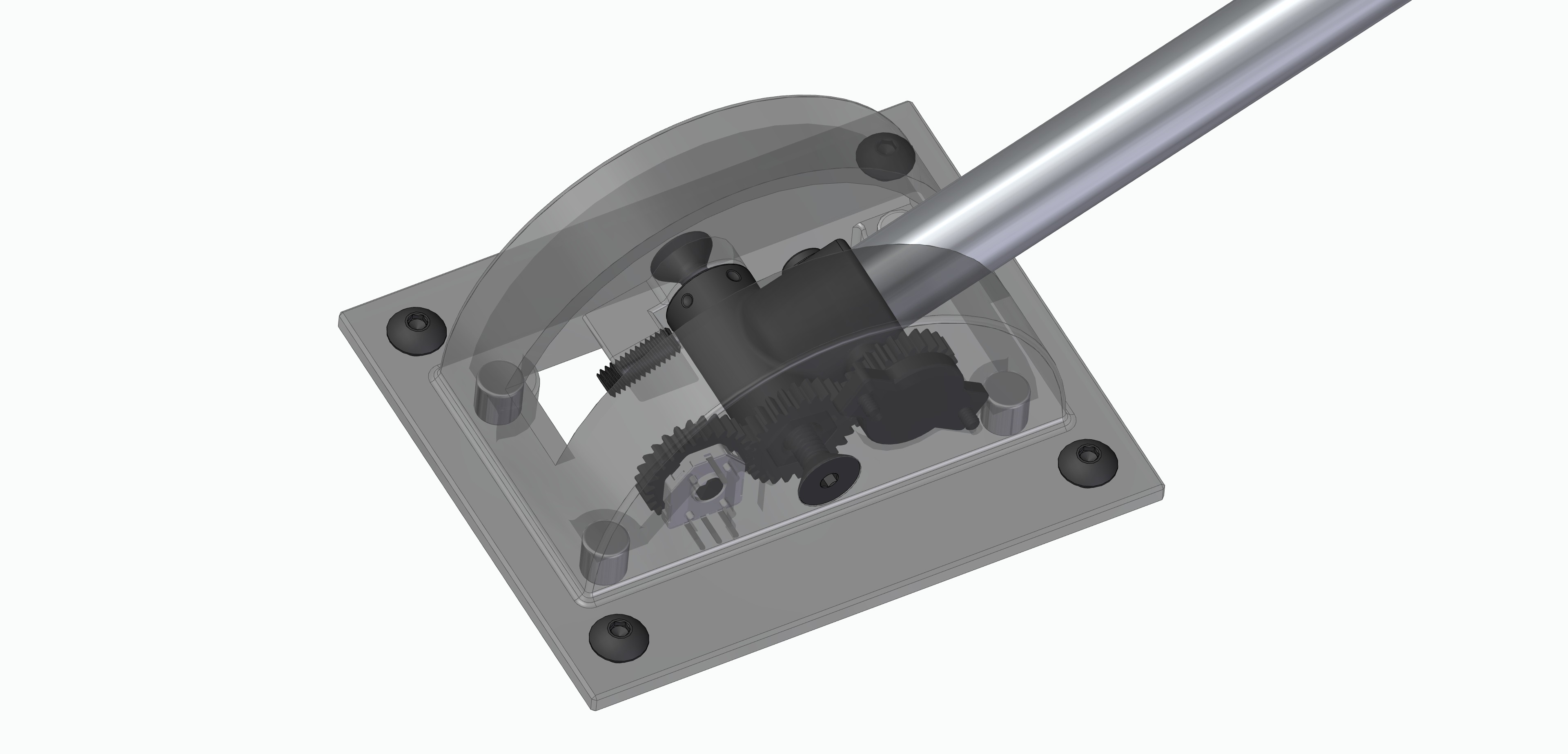
The gearing inside works great. However, the speed limiter is not needed. The lever arm is strong enough that you simply don't get any extra resistance from the limiter, and you can also alter the overall resistance by tightening the axial screws. It is also a pain to install, so I will drop that from the design. The potentiometer fits nicely, but needs to use super-glue and so I am going to see what I can do to make it fit more reliably.
The detent sort of works, part of the issue is the inaccuracy of FDM 3D printing, combined with the layer lines. I think if I want a middle detent that it will have to be some much larger mechanism. I got an idea for that using laser-cut delrin that will be easier to tweak and dial in to the right feel.
The ball and steel rod are so heavy that you have to have it screwed down or magnetically attached to something to move the lever. So as a desk toy it won't work unless the base is made heavier. I may make the final baseplate using 3/16" steel from sendcutsend.com.
I think I will still put in the longer 5.5" rod, as the 5" rod still feels a bit short even though it matches most of the the on-screen photos.
I have completed the design and it is ready to prototype. I ordered a ball from Custom 3D Stuff.
If you think all this stuff I did below is over kill: Well this type of design is what I do everyday.
I added an aluminum round standoff into the middle to act as a shaft.
I have created a Google Drive folder that has all the 3D STL and STEP files,. There is also an exploded diagram along with all the rest of the project files. There is also a BOM here for anyone wanting to get all the hardware. It costs $100 for the ball, thread adapter and related hardware.
I am going to prototype the 3D printed parts on a FDM machine and laser cut the flat parts. I will probably order final parts from Shapeways.
How about some fun image matched GIFs!
I am going to re-calibrate my design to fit better with zenix's version. I can live with using a thread adapter kit. (I didn't know those existed off the shelf)
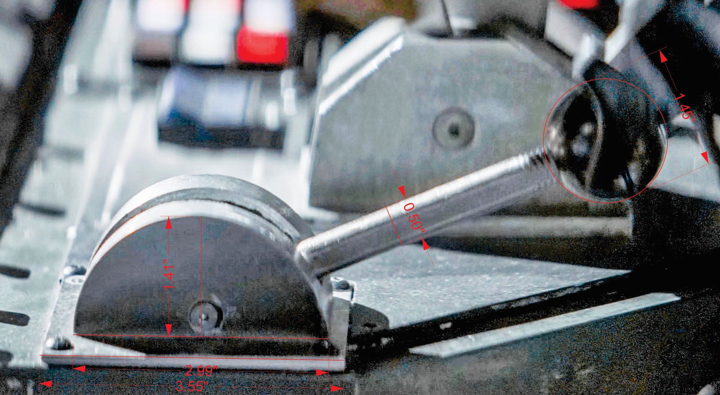
It is quite difficult to get the scale perect, even with the side-on shot. The wide angle camera and perspective throw off all the non planer dimensions. Even with my CAD software set to a 35mm perspective view I find I can't quite match the perspective of the baseplate and the round portion at the same time. Oh, and the screw pivot on the actual prop isn't even perfectly centered left-right. So anything we do will have to be just artistic license and be close enough.
The image below is calibrated so that the shaft is 0.5" then the rest of the planer dimensions are put down.
Okay, so I went a bit overboard on this one. (as always) Currently I want to make this for myself and release the design files once done. (If you want me to start a separate thread let me know)
I took yourgeneral dimensions to start from, but then redid the whole model based on the side image and the ball size you selected. I ended up with a radius of 1.41" and a housing width of 1.66". The shaft is about 3/8" too long, but if you cut that off the threaded end the left over threads will be screen accurate).
I integrated the baseplate into the housing since it looks like there is a weld or casting line on the actual prop. For the corner screws I made them #8-32 tap holes, so you can drive in screws to complete the look even if you use the magnets. The corner screws are not symmetrical on the actual prop, but I couldn't bring myself to place them off center.
To get around the screw self-loosening issue I put the screw threads into the housing, with a clearance hole on the shaft holder.
I added the ball spring, with detents at both extremes and 90 degrees.
I wanted a way to be able to use this to connect to some electronics, it would make an awesome throttle for my Star Wars Squadrons VR rig. So I added a gear to drive a thin potentiometer. Then I realized that to make it feel realistic it needs some smooth friction, so I added a speed limiter on another gear. All this will make the inside look extremely technical and of course and add to the effect.
Too bad that Zenix's replica knob is threaded for M16x1.5mm and McMaster doesn't' carry anything with that thread, I may have to see what I can get on eBay, or make my own ball as you did.


just don't unscrew the lever Knob and give it to the Kid...
https://www.sideshow.com/wp/wp-content/uploads/2021/03/Grogu-Silver-Shift-Knob-768x448.jpg
zapward prop lever, item part #5, refer to diagram
 Maximiliano Palay
 Alex Rich
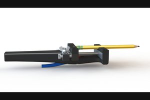
 theschlem
Beautiful!
(The aluminum tape idea is great!)