 Enrico Gueli
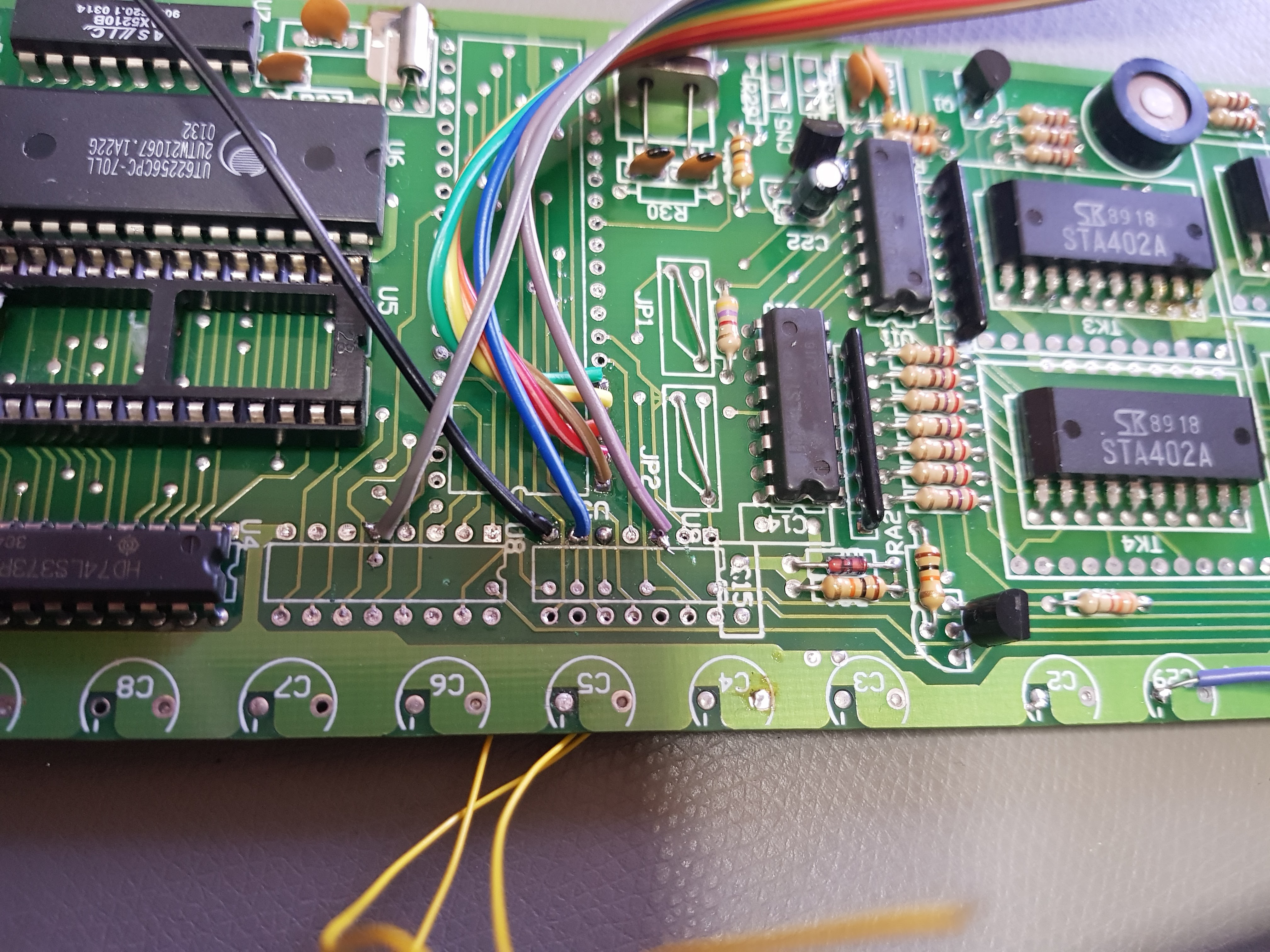
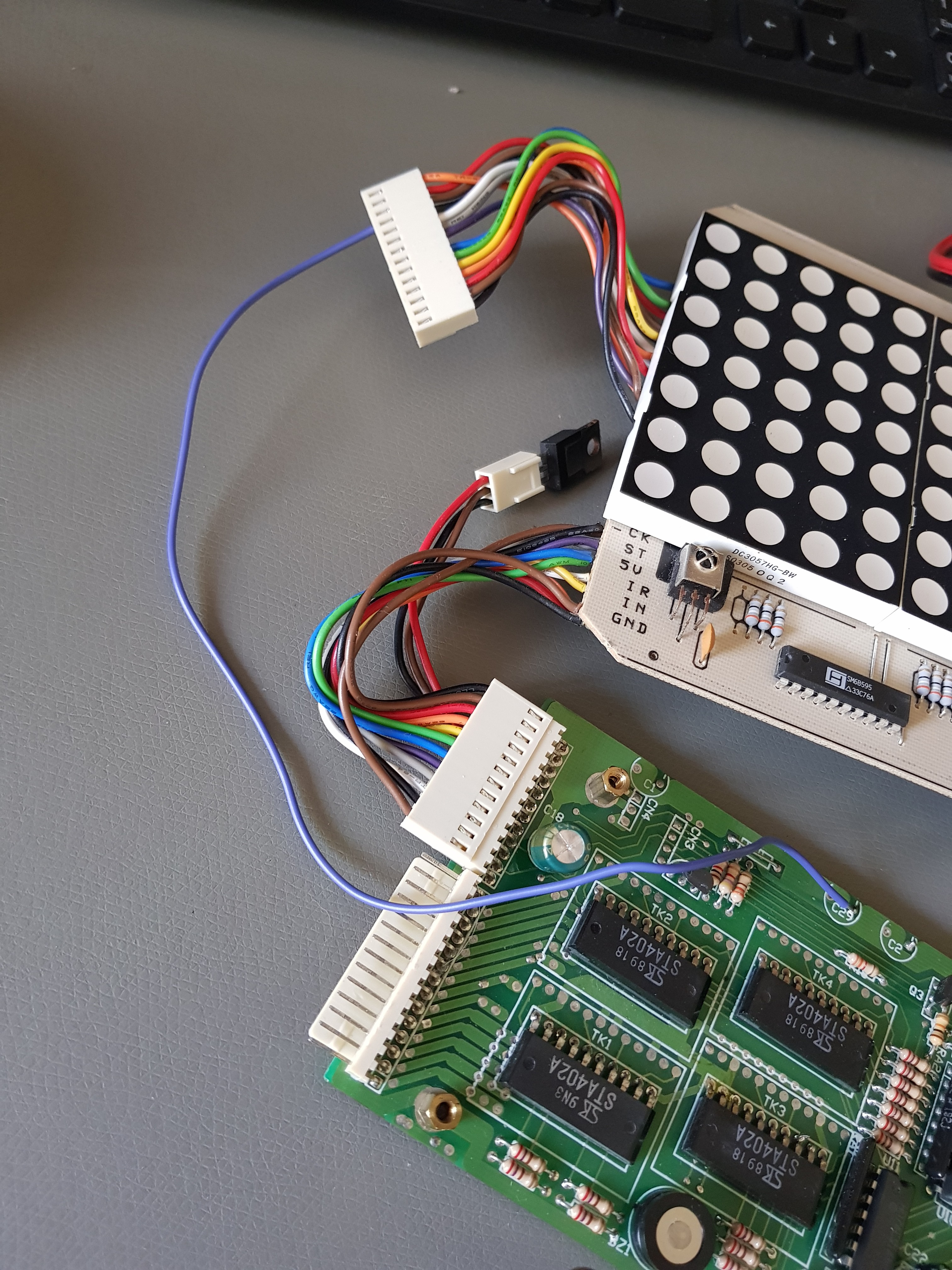
Desoldering the three chips gave me access to the signals that control the LED matrix:
- Row control, bit 0
- Row control, bit 1
- Row control, bit 2
- Row control, bit 3 for green LEDs
- Row control, bit 4 for red LEDs
- Column control, serial clock
- Column control, strobe
- Column control, serial data
The numbers on the list above match the "resistor color codes" of the wires I soldered on the board:
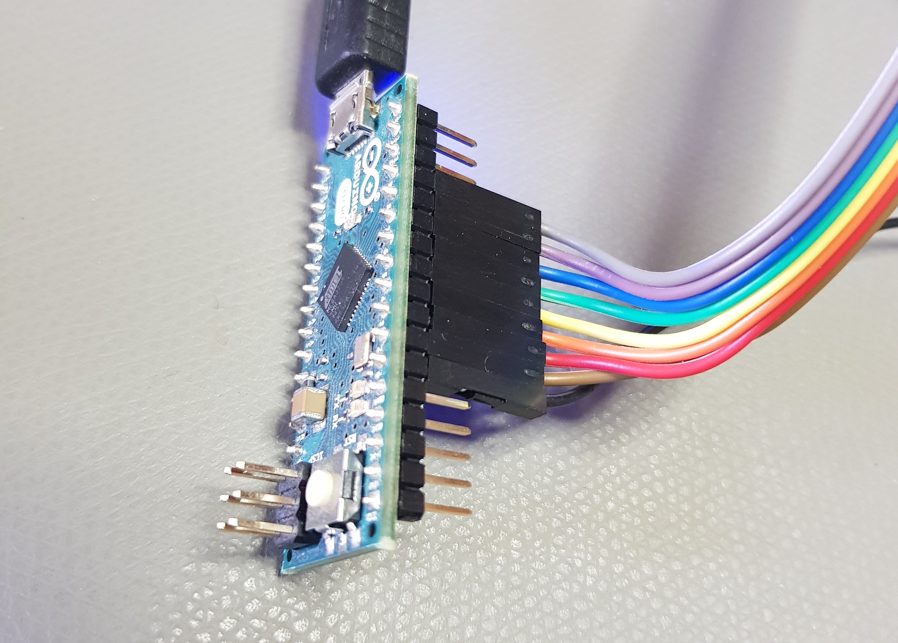
At the other end of the wires, an Arduino Micro:
My objective for now is to be able to draw something with an Arduino at least. Since it's all 5V powered, that seems the easiest goal for now. I plan to reach that goal in three steps:
- with a row powered directly by power supply, verify that the shift registers are used correctly;
- with a single column turned on, verify that all the rows can be activated
- try it all with some bitmaps or text
I've managed to do step 1, after finding a small mistake in the wiring (as the purple and gray wires are really similar in color in these wires). I can now control each of the LEDs of an individual row:
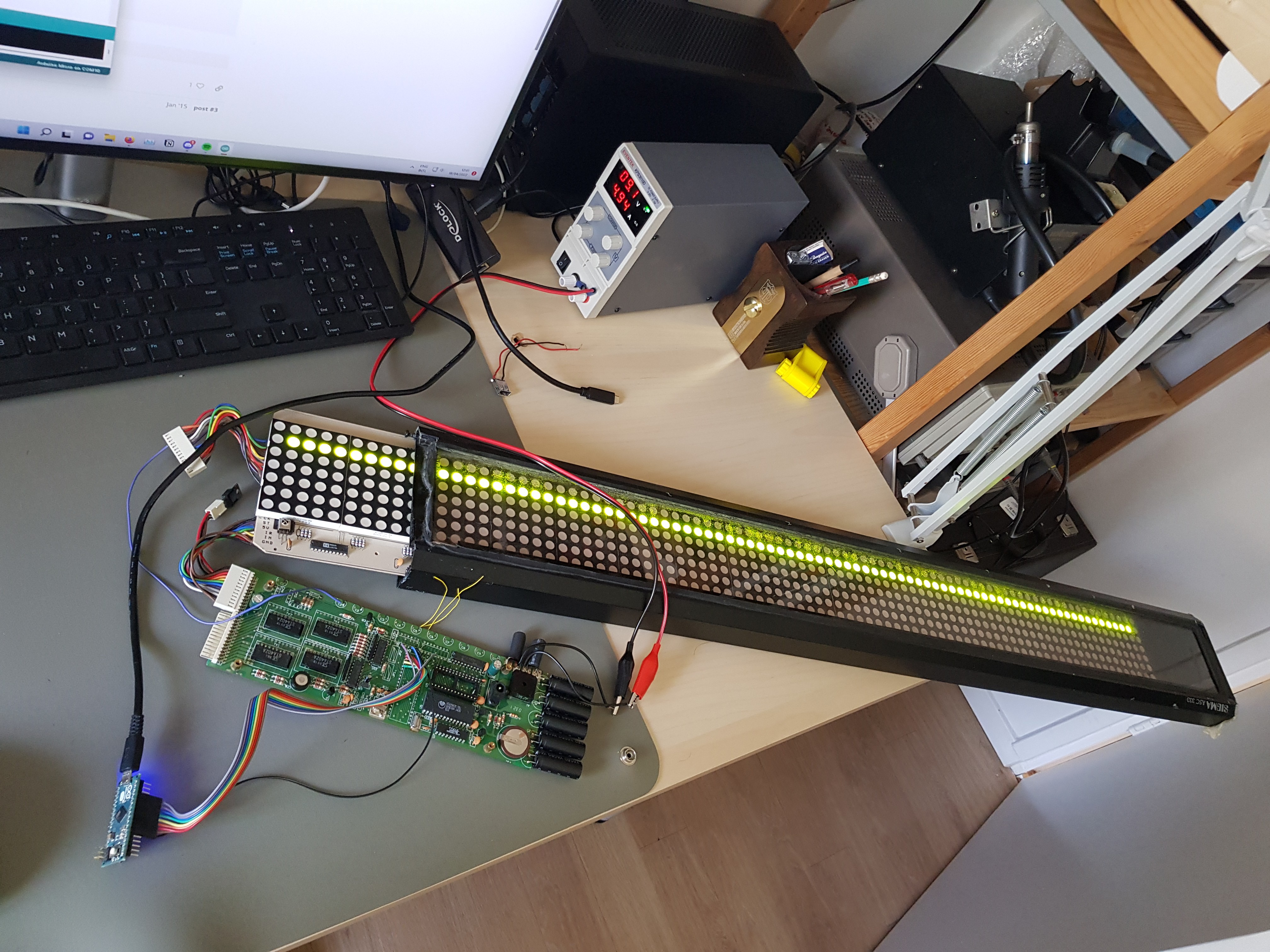
The thing draws 5A, that's 45W of power, same as specified in the power rating behind the case. That bridge rectifier is too hot to touch, but I think it can stand that.
Discussions
Become a Hackaday.io Member
Create an account to leave a comment. Already have an account? Log In.