 marcoA152
This project starts in 2020 during pandemic lockdown, after that it have loong periods of dust collecting.
Now is ready to start collect data and I want to share the code and the setup with the community!
Short story:
in the first version i've planned to record data on an SDcard as txt file and do not use any battery related precautions (a power bank that lasts some hours)
then the second version saves data on sd card + via Bluetooth Serial (android app) the data will be transmitted to a mobile phone and then parsed in excel
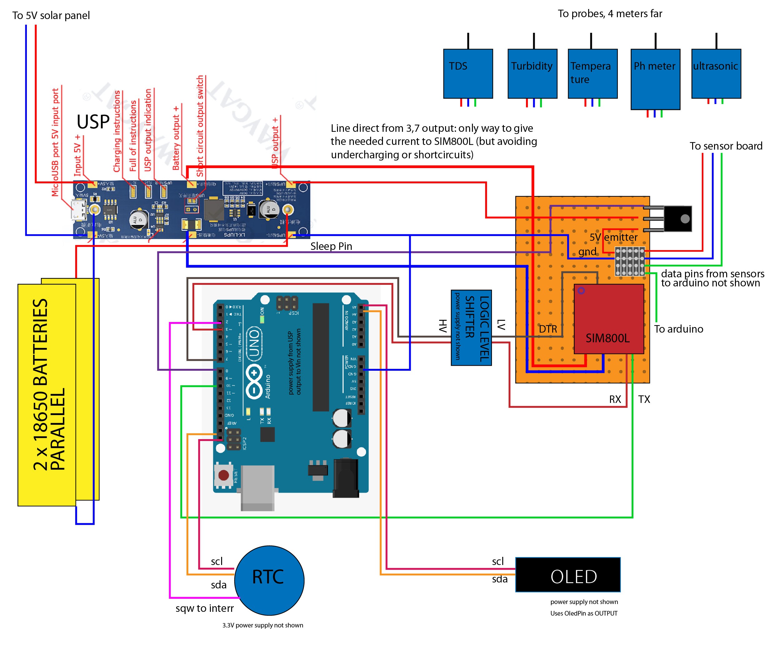
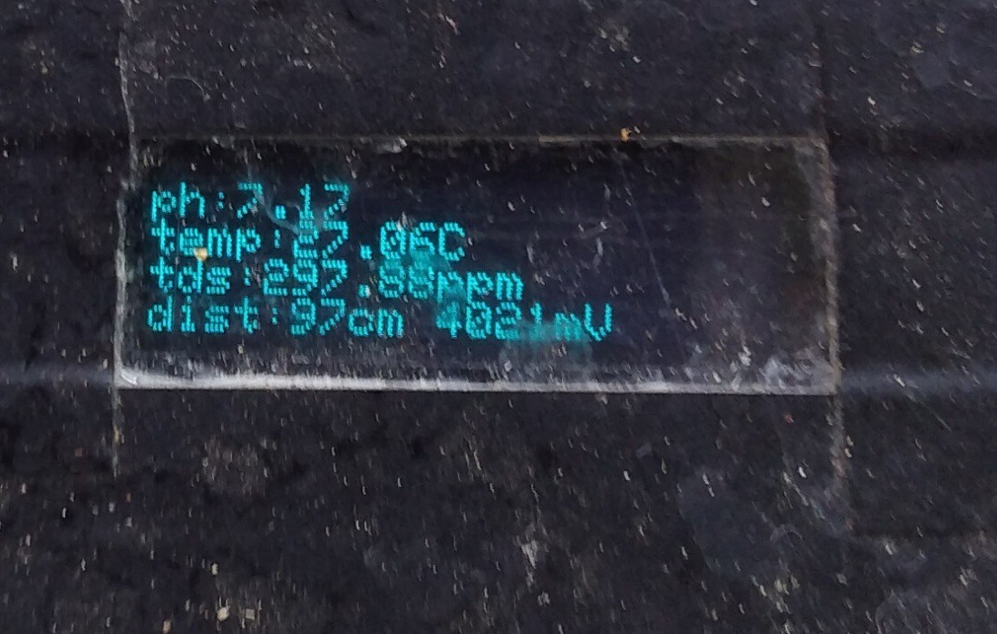
the latest version do not store data, but the readings are sent to thingspeak via a SIM800L module.
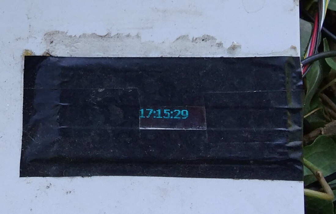
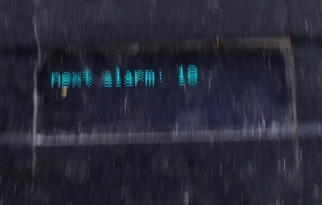
with a RTC (real time clock on pin 2 as interrupt) the device exit from deepsleep every 6 hours.
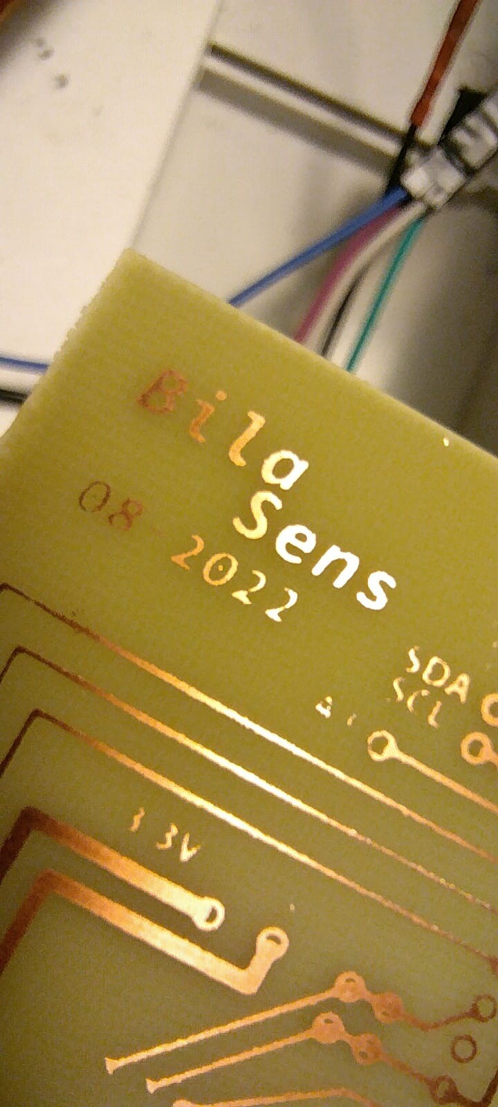
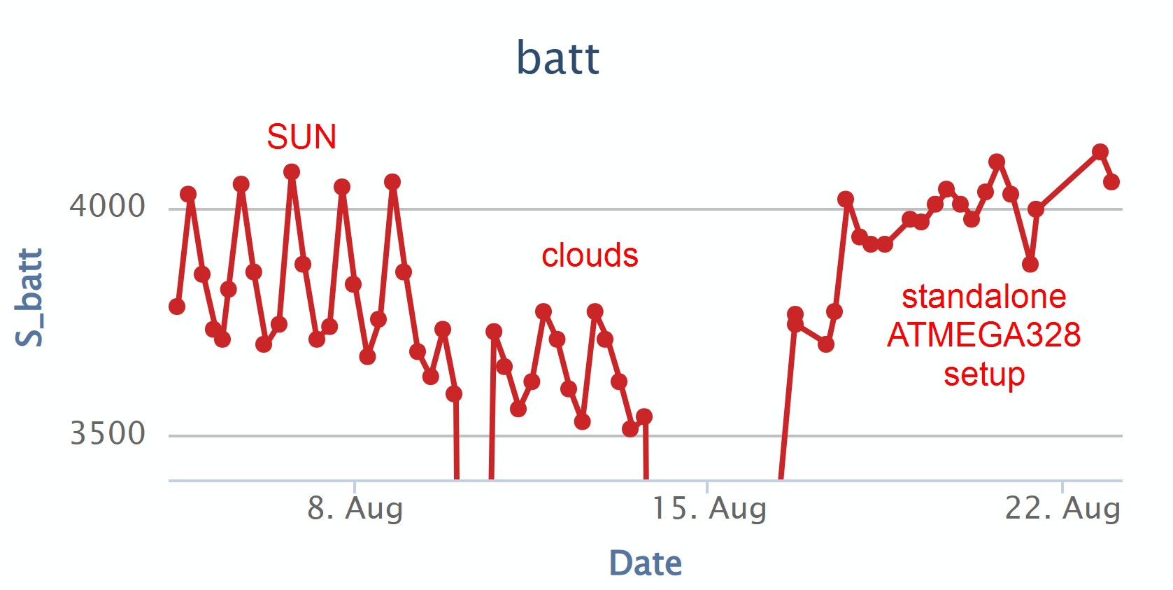
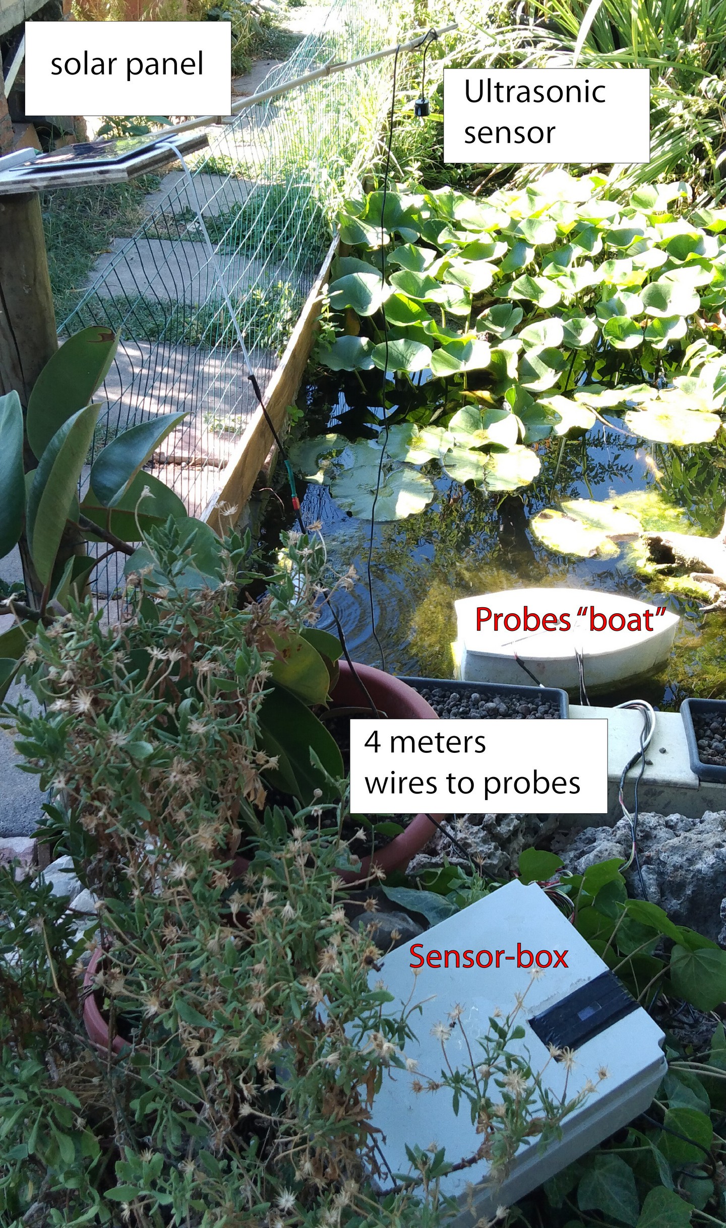
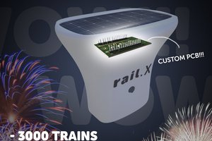
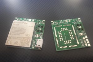
As power supply it uses two 18650 batteries with a small solar panel. To improve battery life on cloudy days now it works with a custom PCB with a standalone ATMEGA328p
As environmental guide I work on a river (canoeing) and the curiosity to know some river's parameters is obviously great!
This log is intended as self-learning work, if someone have some suggestion on my hobby-work feel free to comment!


 from another view
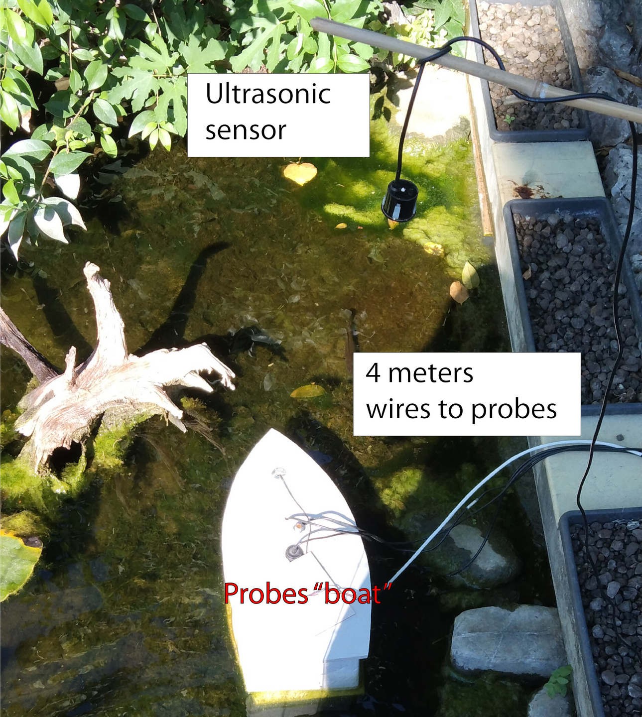
 jan.marcinowski
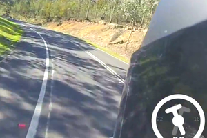
 Simon
Simon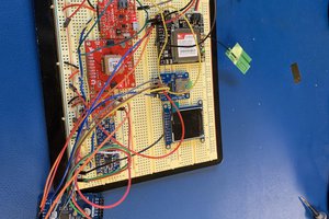
 Raúl Luna