 Sagar 001
I made 2 different oscilloscope and these are featured on this platform. And now I came up with an idea of dual channel oscilloscope. This one has main microcontroller as Arduino and 1.3” OLED display. This time I also have battery operating options and onboard charging circuit also. You can make this on breadboard first and then go with my PCB layouts given below. A big shoutout to JLCPCB to sponsor this project of dual channel Arduino scope.
This is not only the scope, also have some extra features of DDS_PWM (function generator with 8 different waveforms), Pulse generator and frequency counter. I find this project on a Japanese webpage, but all the explanation is here for you guys.
Features:
The max real time sampling rates are 17.2ksps with 2 channels and 307ksps with a channel. The max equivalent time sampling rates is 16Msps with single channel.
- Single-channel -30Khz bandwidth
- Onscreen- Volt/Div and Time/Div
- Duty cycle monitoring
- Small 1.3 inch I2C
- AC/DC measurements option
- Mode changing, Hold state features
- Dual channel Switching mode
- Pulse generator option
- DDS_PWM waveform generator
- Frequency counter
- Low battery consumption
- Portable and pocket-sized
Important note:
This project is only for educational purposes and shows the capabilities of a 16Mhz 8-bit microcontroller board. This MCU Can support frequencies below 50KHz, so it can’t be applicable for commercial and professional uses. That way, the project can also be entitled POOR MAN OSCILLOSCOPE for me. Also I found this helpful in project related to audio frequency below.
Display:

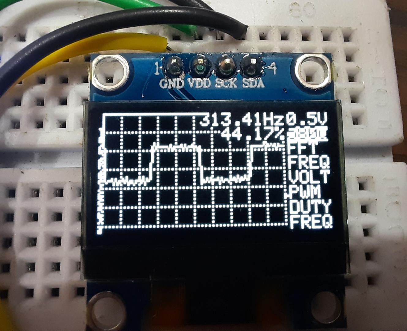
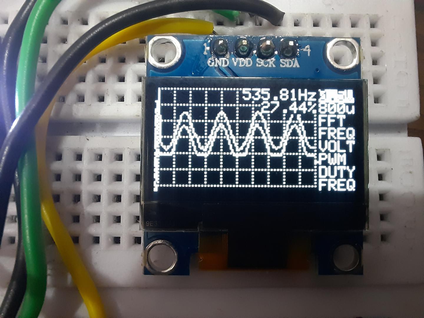
1.3 -inch OLED display with I2C function comes with two different models, SSD1306 and SH1106, to change the code as per requirements. We have to uncomment which version of LCD we are using in this project. And the screen is able to represent the nature of the wave with duty cycle and frequency in two channels.
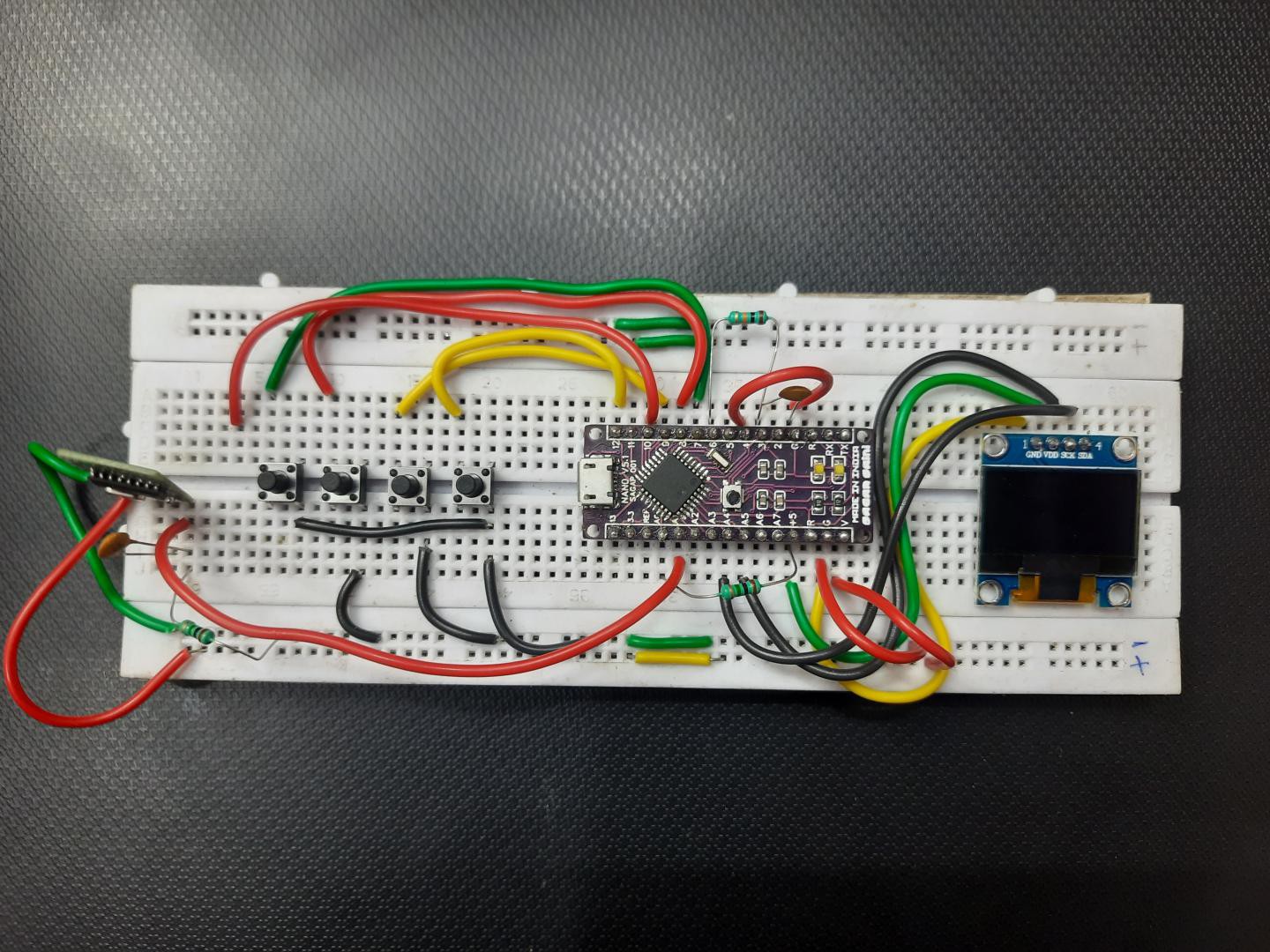
Components used:
- Arduino Nano
- 1M resistors
- 10k resistors
- 1.3 inch OLED display
- 100nF capacitors
- 4 tactile buttons
- 5v power supply
Pictorial circuit diagram:

As always this is the pictorial circuit, I minimized the circuit to its operation of one channel. if you want to utilize both channels just follow the main circuit diagram given below.
And big thanks to "Cirkit designer" software for proving such a great tool to present the circuit and wiring in pictorial format. This will be a easier method to understand for a newcomer or students.
For now cirkit designer is available in free for all (Download from Here), so there is no reason not to take advantage of this offer. As a review, I found this very helpful for my projects. some special features of the software are: code compilation, BOM manager, Breadboard and Custom components creating.
Circuit diagram:
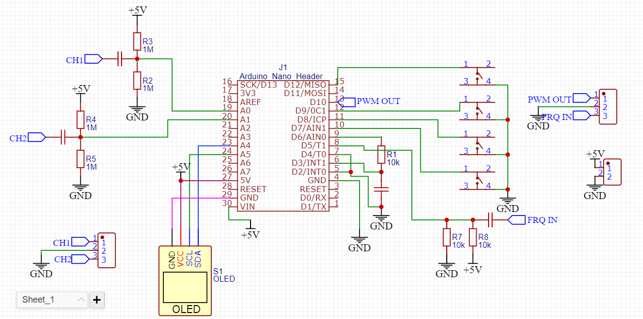
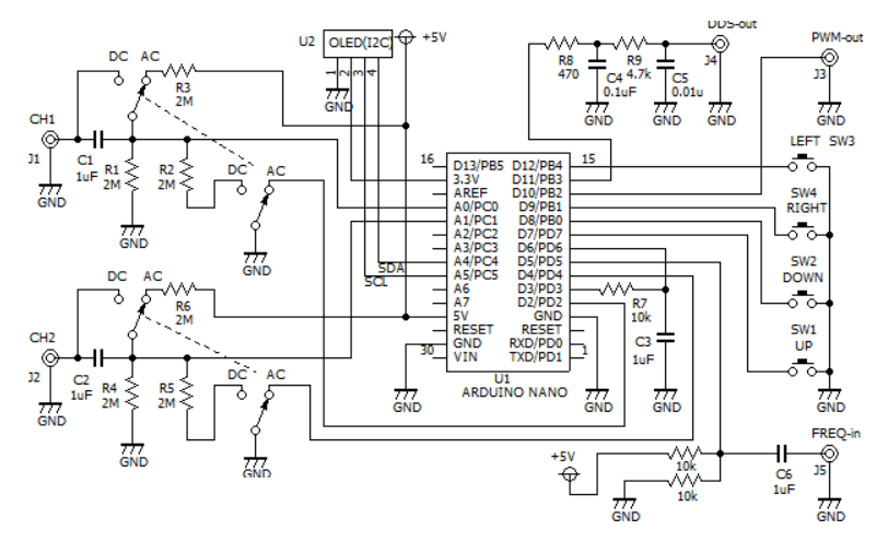
Circuit description:
Pin usage
A0 oscilloscope probe ch1
A1 oscilloscope probe ch2
A4 I2C SDA
A5 I2C SCL
D3 PWM output for trigger level
D4 Up button
D6 trigger level input
D8 Down button
D9 Right button
D10 Pulse generator output
D11 PWM DDS output
D12 Left button
This small oscilloscope can be powered using 5volts @200mA. You can see two different circuits above, both are fine but one made by me is simplified and most useable in all cases. you can modify the circuit as per own.
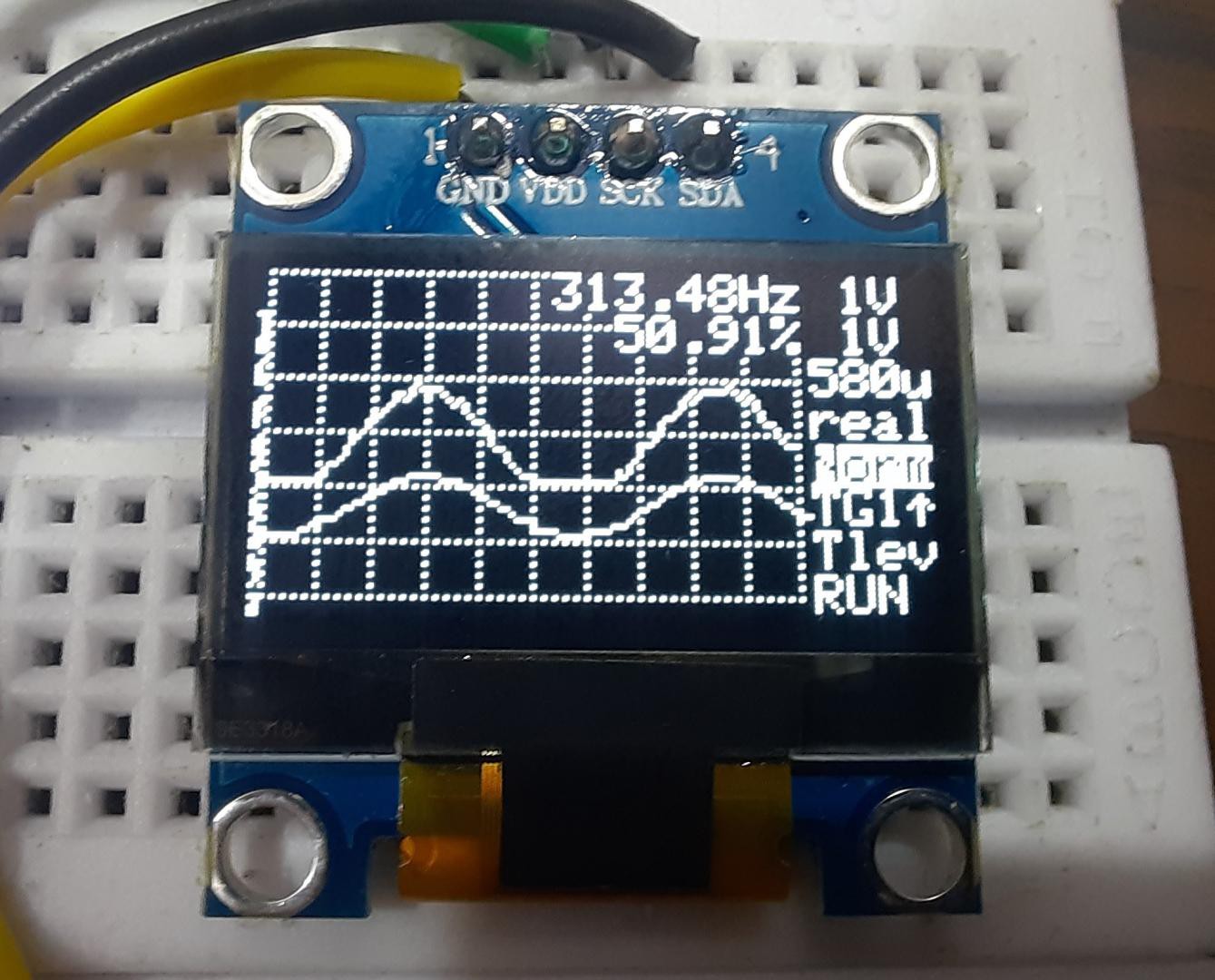
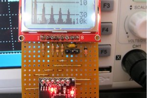
Just have a look on those pretty waves in the oscilloscope.


This time the circuit also have external frequency measuring and PWM, DDS pulse output options with 2 channels. 4 tactile button is to trigged on pulling down. All the resistors are for proper baising. As a improvement you can made the PCB layouts of your circuit and order them just in $2 from JLCPCB. By the way if you want to use mine, given below you can download. Sign-up using my link will give you PCB coupons as reward for Prototype SMT service. Why not take advantage of $27 worth coupons in free.
Exploring the Menu:
Full menu has more options than the previous arduscope project. Yet, I don't get the big screen. May...
Read more »
 mircemk
 agp.cooper
 Jithin Sanal