0%
0%
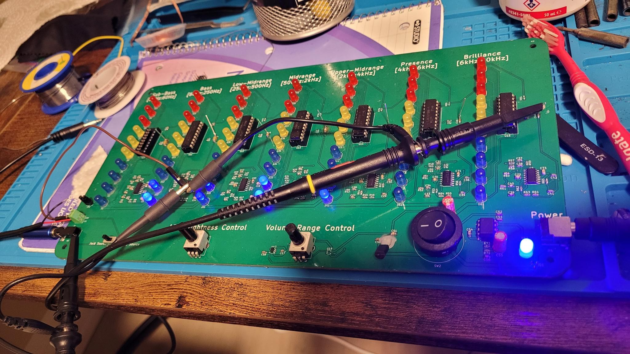
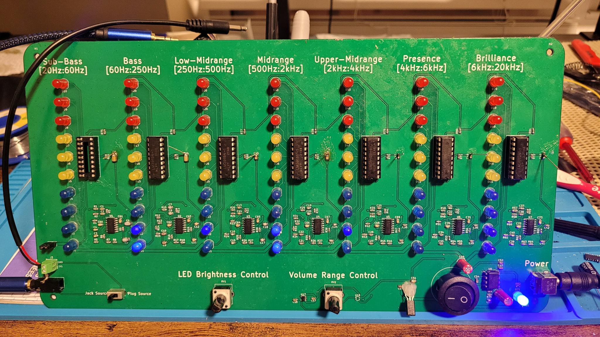
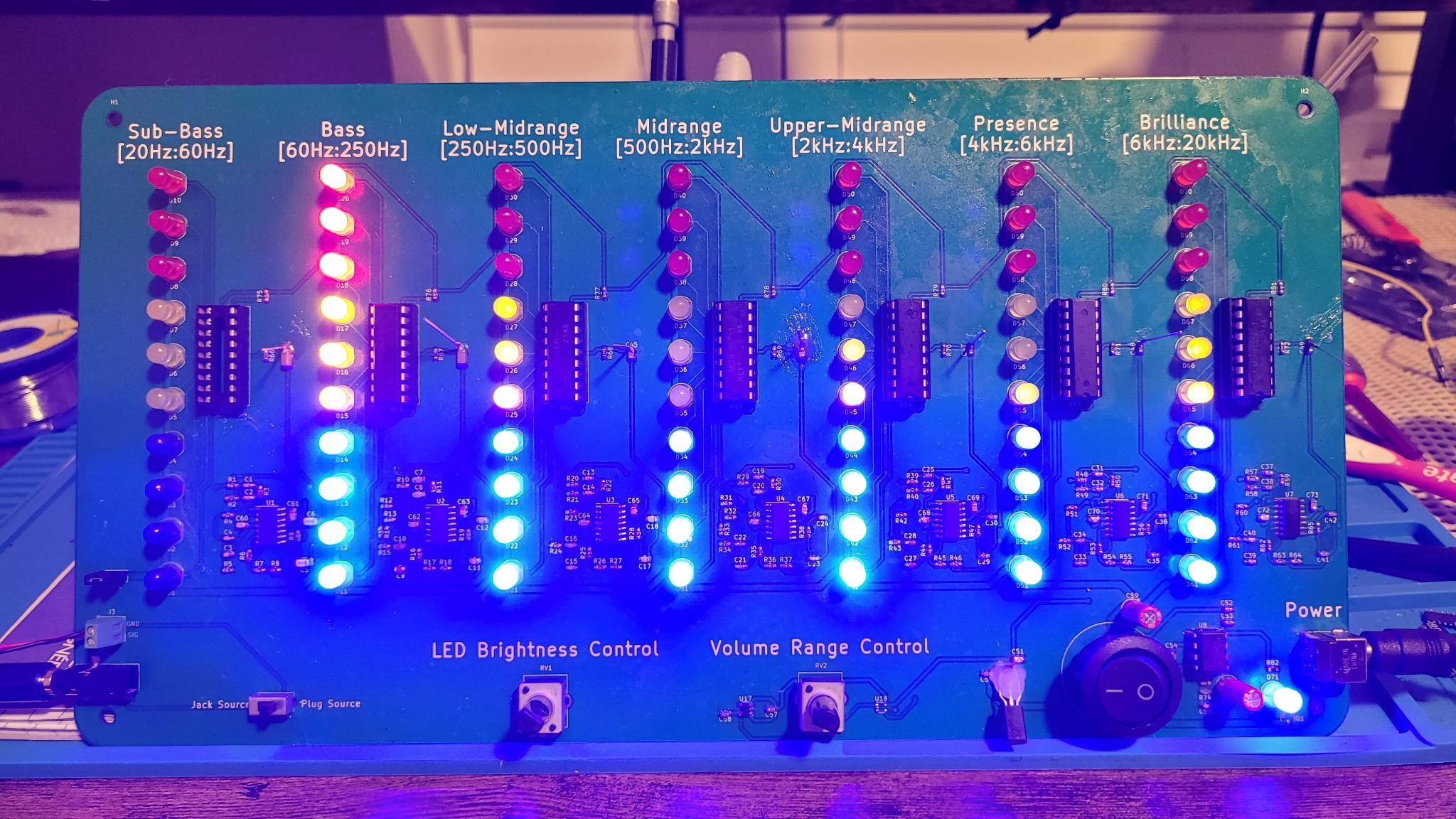
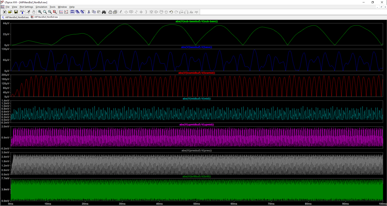
Music Spectrum and dB Visualizer
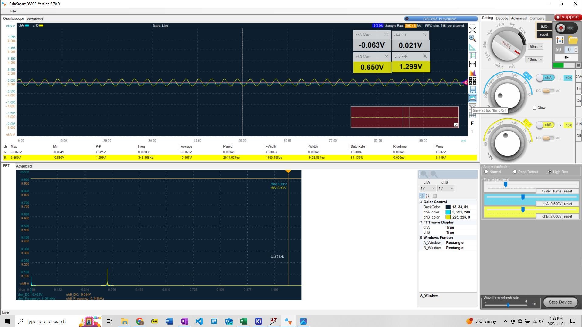
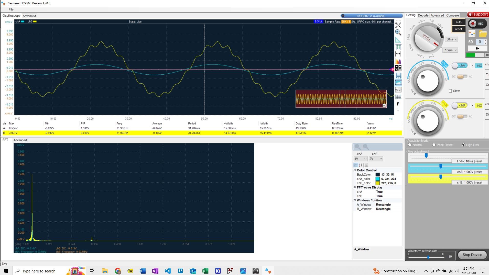
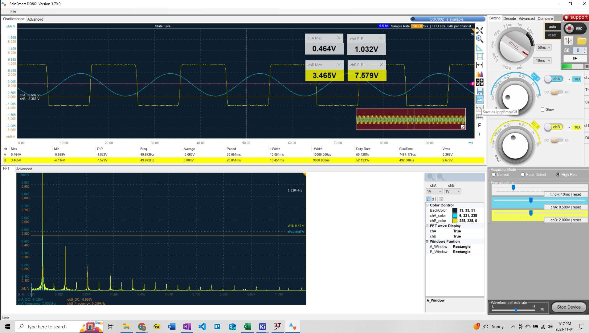
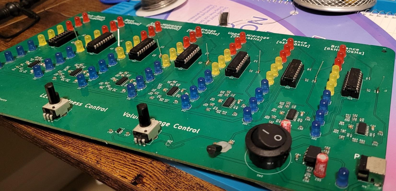
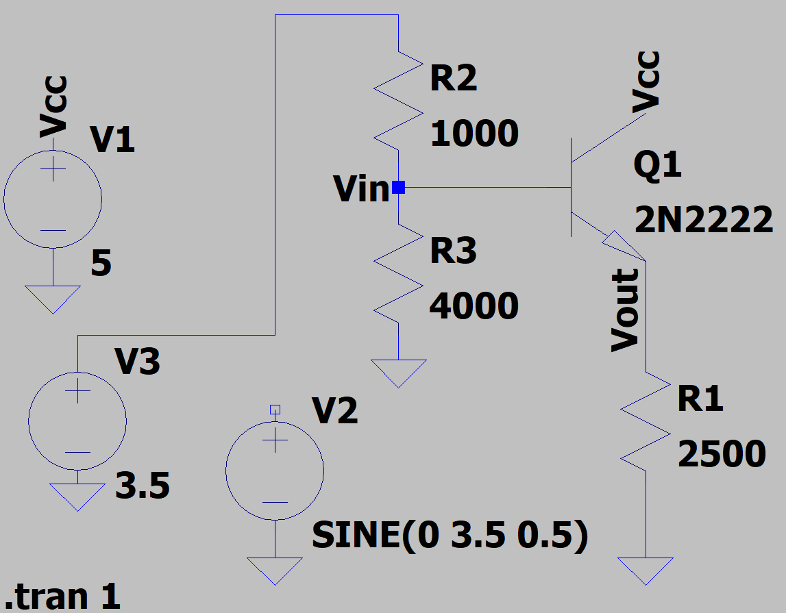
Receive input from a 3.5mm jack, divides the music into 7 frequency bands, shows the loudness of each frequency band in DB using LEDS.
 Ghani Lawal
Become a Hackaday.io member
Already have an account? Log in.
Just one more thing
To make the experience fit your profile, pick a username and tell us what interests you.
Pick an awesome username
hackaday.io/
Your profile's URL: hackaday.io/username. Max 25 alphanumeric characters.
Pick a few interests
Projects that share your interests
People that share your interests


 Petteri Aimonen
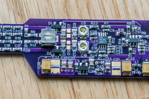
 Bud Bennett
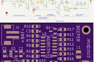
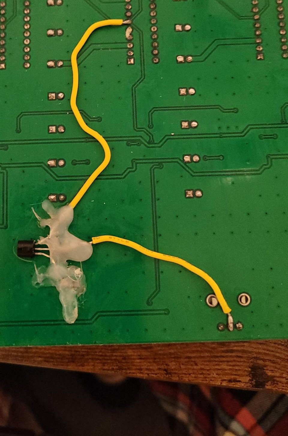
ahahah yeah I underestimated how hard they would be to solder