ElectronicABC
GERBER PCB:
https://mega.nz/file/XUwlCJSJ#Zr_GPcgHgqShUZLQuiK4ck5ZpwO5N9rXWhcWyhYQcVk
DATSHEET NE555
https://mega.nz/file/OcAEBarY#XssaDHa88vFlo362_nrN6C0kOcOjHYfRn-hmuKF6tGE
DATASHEET CD4017:
https://mega.nz/file/zRJgFRJK#ayrm5eF_sP0794eCOJCPdpwAxofcT7BAMNLnhsyV3t4
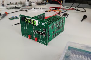
Due to the great advance of technology, we now require innovative systems that allow us to control the lighting in our home or office, whether it is turning LED lamps on or off. This project is basic and easy to carry out because it does not require knowing much about electronics, but rather basic concepts so that one can carry it out by oneself.
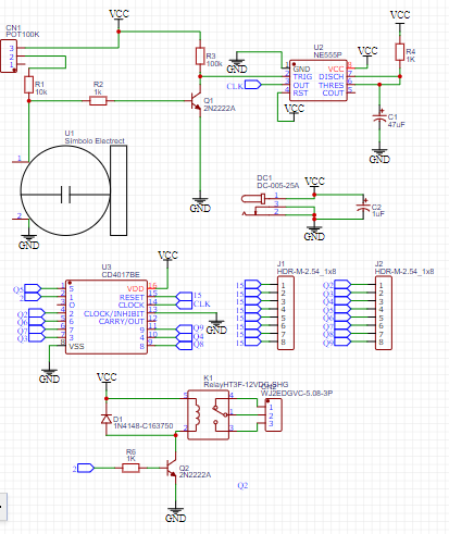
We will initially see the schematic diagram where we can see that there is a monostable circuit with the IC ne555 where we can calculate the output pulse time with the following formula T=1.1xRC.
We will also see an ELECTREC at the input that will allow us to disappoint the clap or applause that we will send, this in turn will go to the MONOSTABLE circuit and will activate its output for a short time, then the output of the NE555 will go to the CLOCK pulse input of the CD4017 and thus will allow us Turn on the 220VAC LED when RESET pin 15 is connected to Q2, so it can be clapped on and clapped off.
The CD4017 is a counter/divider or decorifier with 10 outputs. Structurally, it is made up of a 5-stage Johnson counter that can divide or count by any value between 2 and 9, with resources to continue or stop at the end of the cycle.
Also known as a sequencer circuit, that is, at each input pulse the output will increase and later it will also turn off.
In this project we will obtain 8 possible configurations of pulse ignition, that is, through the reset we configure the amount of applause to turn on and only with an applause we will turn off.
· Q2=1 APPLAUSE
· Q3=2 APPLAUSE
· Q4=3 APPLAUSE
· Q5=4 APPLAUSE
· Q6=5 APPLAUSE
· Q7=6 APPLAUSE
· Q8=7 APPLAUSE
· Q9=8 APPLAUSE
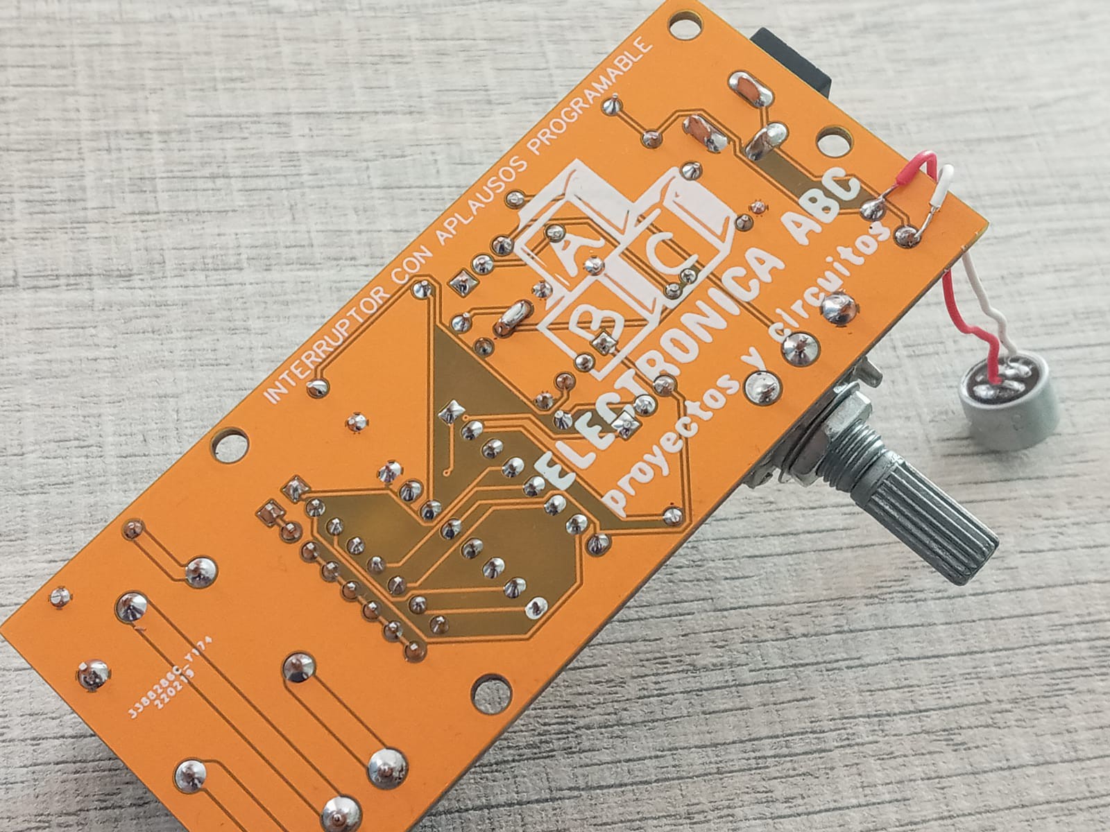
There we observe the configuration of the amount of applause to turn on the 220VAC LED bulb and we can do it by connecting PIN 15 of the CD4017 to the amount of applause to turn on.
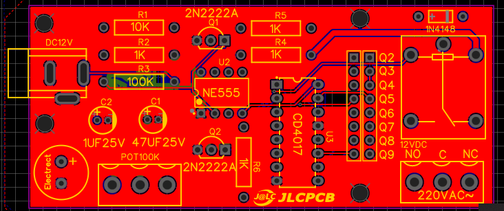
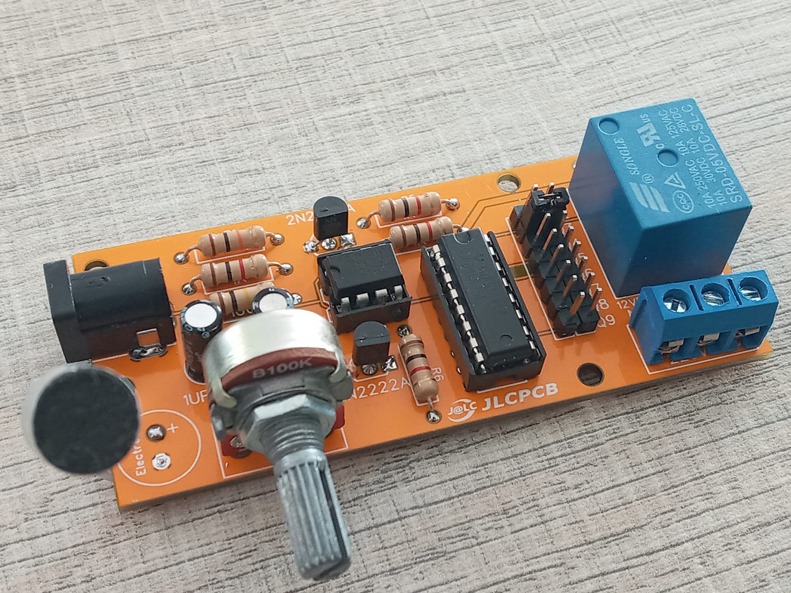
ELECTRONIC COMPONENTS:
- 1CI NE555
- 1CI CD4017
- 1 DC JACK
- 1 BLUE TERMINAL BOARD 3 PINS
- 1 RELAY 5V
- 2 TRANSISTORS BJT 2N2222A
- 1 100K POTENTIOMETER
- 4 RESISTORS 1/2W 1K
- 1 RESISTOR 1/2W 100K
- 1 RESISTOR 1/2W 10K
- 2 BLADES 8 PINS
- 1 CAP. ELECTROLYTE 1UF 25V
- 1 CAP. ELECTROLYTE 47UF 25V
- 1 JUMPER
- 1 ELECTRIC MICROPHONE
- 1PCB
CIRCUIT CHARACTERISTICS:
- VIN 5VDC
- IMAX 100mA
- 1 OUTPUT 220VAC 10A
- PROGRAMMABLE CIRCUIT SENSITIVITY
- EFFICIENT
JLCPCB
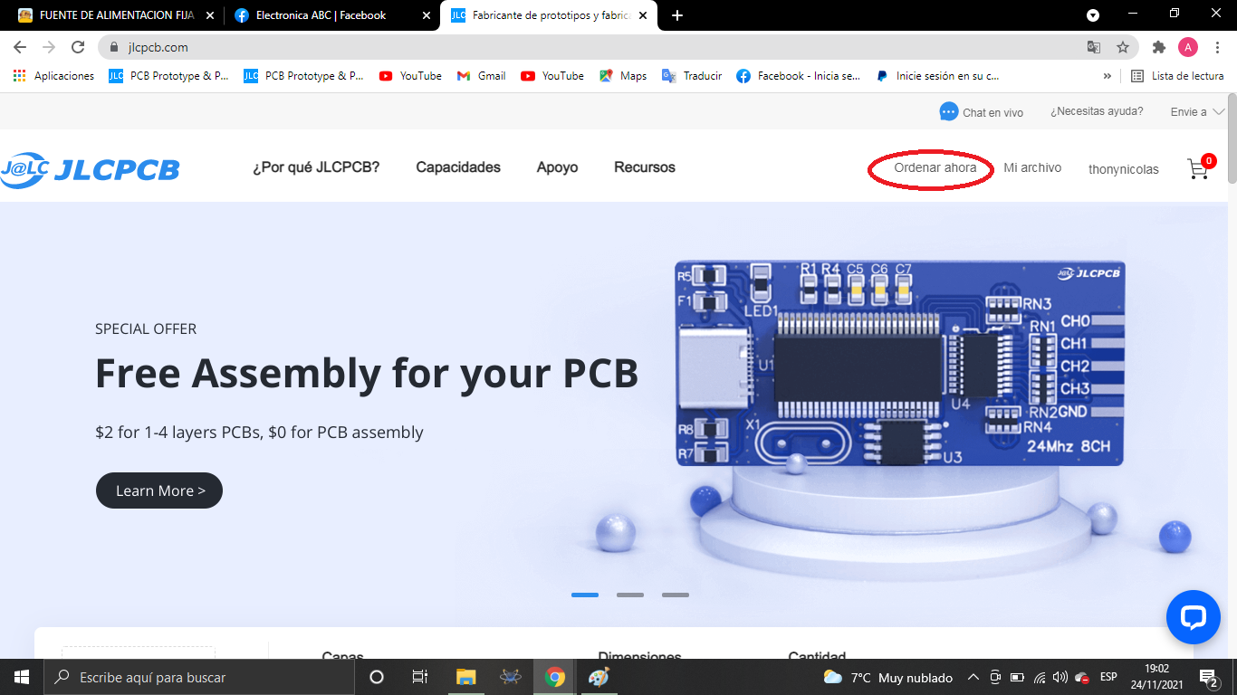
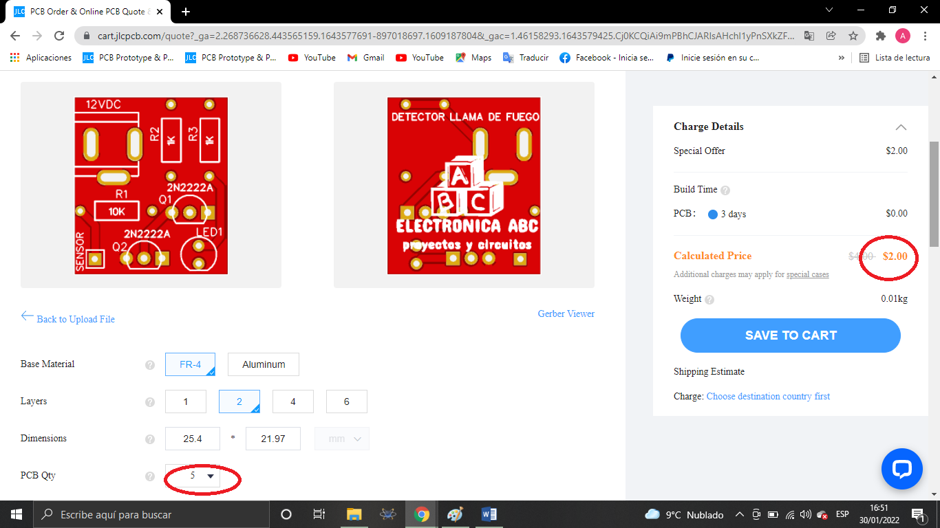
we thank JLCPCB for the professional pcbs you can purchase
5 pcbs a $ 2
order your pcb here:
Gerber:
https://mega.nz/file/zM4HUKrQ#UQoz6jh9dnY1aeTuF_lFwfqFk5nBVBz8lWoU_vE1Yrw
 Melvin van Kalsbeek
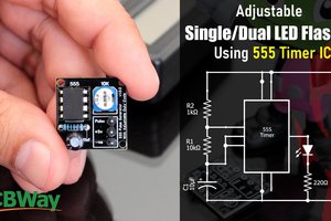
 Hulk
Hulk