 Lithium ION
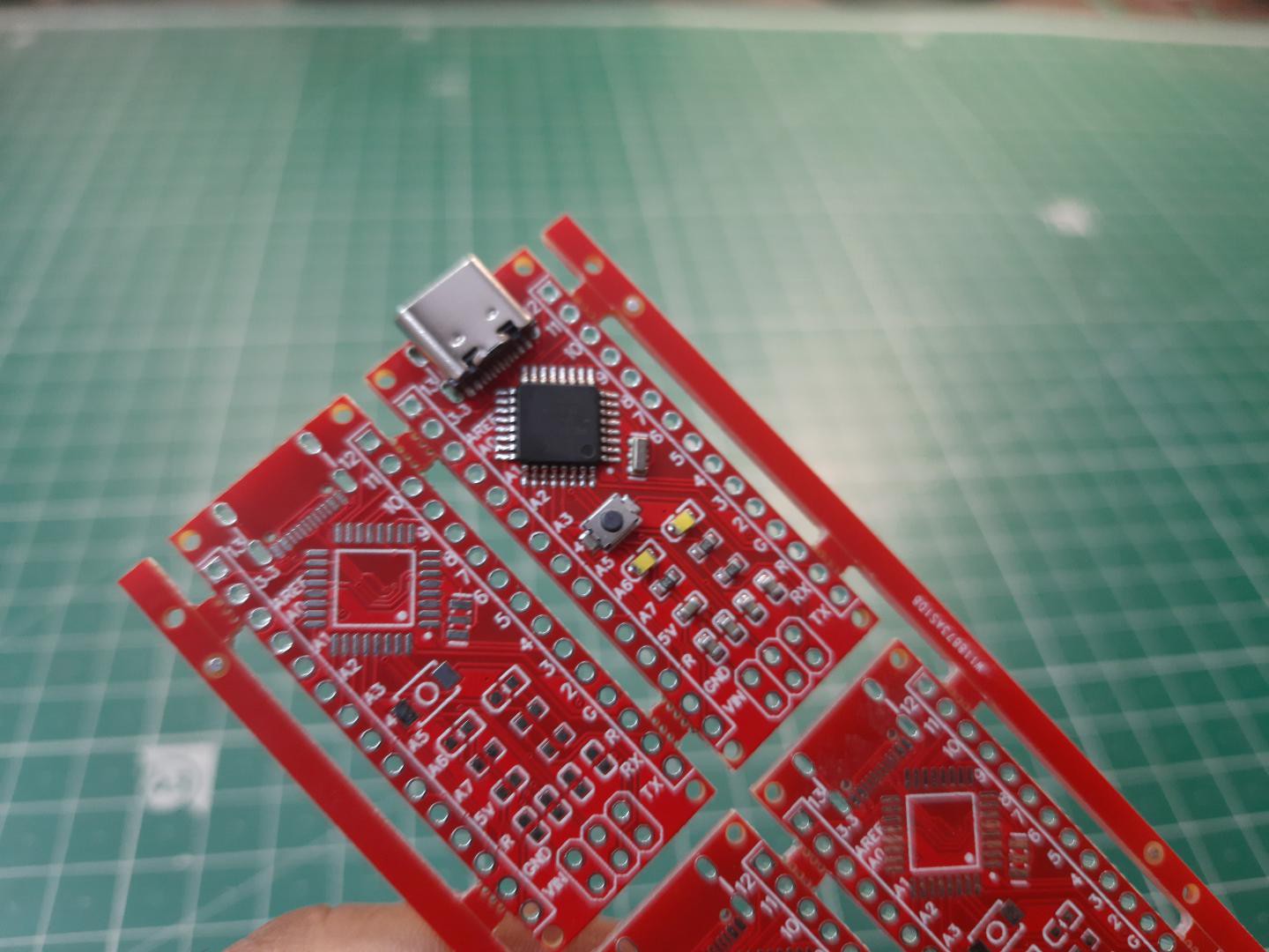
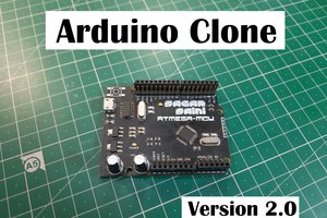
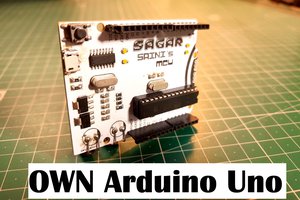
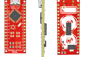
Here is my new Arduino Nano board, This looks better with C-type and one step above compatible drivers. I faced many problems in making the PCB, but I think PCBWay is the solution to all of them with their prototype PCB capabilities.

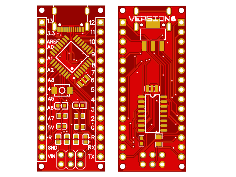
And looks of the pcb also matters, see this tiny cute beast. Whatever, let's have a look on the specs and circuit diagrams.
Arduino microcontroller:

Arduino UNO chip are available broadly in two different packages, SMD and DIP. Because here we are using this with Arduino Nano compatible board, so we are using 32 pin SMD chip. Here are some specs of the MCU:
Specifications:
- Microcontroller: ATmega328P
- Operating Voltage: 5V
- Input Voltage (recommended): 7-12V
- In/out Voltage (limit): 6-20V
- Digital I/O Pins: 14 (of which 6 provide PWM output)
- PWM Digital I/O Pins: 6
- Analog Input Pins: 6
- DC Current per I/O Pin: 20 mA
- DC current for 3.3V Pin: 50 mA
- Flash Memory: 32 KB (ATmega328P) of which 0.5 KB used by bootloader
- SRAM: 2 KB (ATmega328P)
- EEPROM: 1 KB (ATmega328P)
- Clock Speed: 16 MHz
- LED_BUILTIN: 13
Circuit Diagram:
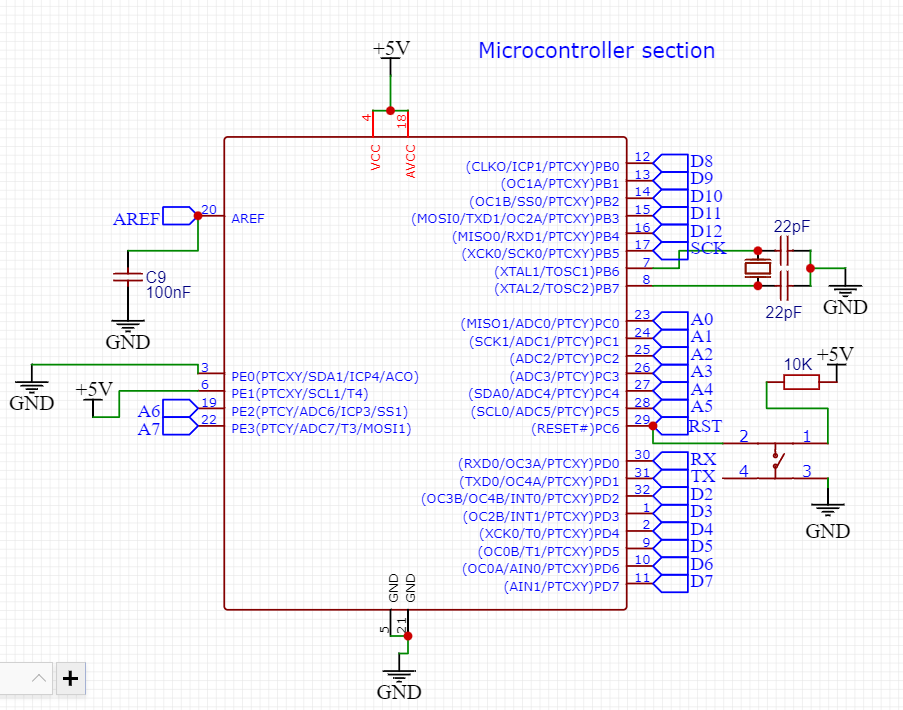
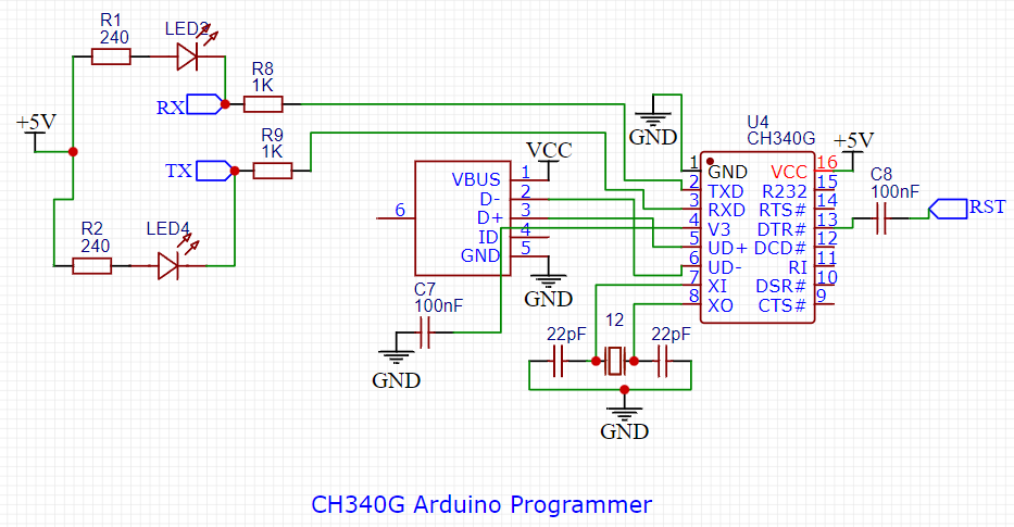

I am sharing the proper schematics with you, In the first image you can see microcontroller section, then programmer chip section and power section. You can also Download full PDF of this circuit from here.
Components Required:

1) AtMega328p (SMD version)
2) CH340G Usb to TTL (For programming)
3) USB Type C JACK
4) 100nF (104) capacitor
5) 16Mhz crystal
6) 1k resistor
7) 10k resistor
8) 603 smd led white
9) Ams1117 5volt
10) Custom PCB (PCBWAY)
Circuit Description:

The most challenging thing is to keep the cost as low as possible, so we tried to go with ch340 programmer chip, which is directly connected to USB and known as USB to serial chip. RX and TX pin is connected to MCU with a 1k resistors and DTR pin to reset with 100nf capacitors. To give a proper clock signal to MCU a 16MHz SMD rasonator is there. Ch340C is used as USB to serial programmer has inbuild 12MHZ crystal for clock. Reset pin is connected to 5v with 10k resistor and pulled down whenever we have to reset the programmer. Some capacitors are used to reduce the noise in signals and There are 4 indicating led's for RX, TX, Power and D13.
PCB layout and ordering:
I want to make the exact same form factor PCB as Arduino Nano. So, I designed the PCB keeping the pins and voltage in mind. Download my Gerber files from here.
For the professional looks, I am using PCB prototype service from PCBWAY. The ordering process is too simple, Sign-up to PCBway using this link.
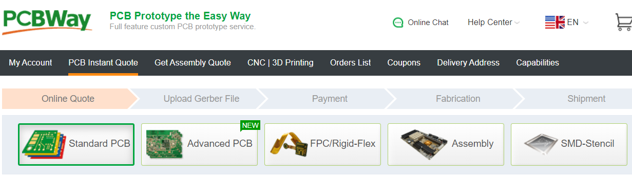
Then choose the PCB size and other parameters of color, surface finish and material.

Add it to cart > Upload the Gerber files > CHECKOUT and get your package in just 7 days.
Soldering and Assembling:

Because I want these PCBs for my college students, I am using paneled PCB. So, that we can make more microcontroller boards in less time.
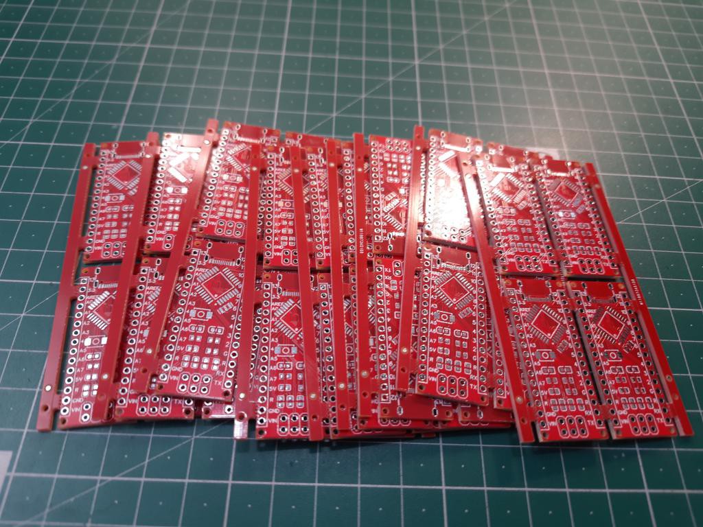
I ordered the stencil also from PCBway, the full review to it is here. both top and bottom layer is printed on this single stencil.
Then I placed all the components and this is the time to solder. Because I don't have any hot plate, my home made Iron can do the job. As per bottom layer hot air gun is the best method to solder.

Uploading first sketch:
You can download the proper drivers for ch340c programming chip from here, also I am assuming here that bootloader is pre uploaded in the chip. So after that you can try below given blink sketch to check the action of MCU and programmer.
Code:
// the setup function runs once when you press reset or power the board
void setup() {
  // initialize digital pin LED_BUILTIN as an output.
  pinMode(LED_BUILTIN, OUTPUT);
}

// the loop function runs over and over again forever
void loop() {
  digitalWrite(LED_BUILTIN, HIGH);   // turn the LED on (HIGH is the voltage level)
  delay(1000);                       // wait for a second
  digitalWrite(LED_BUILTIN, LOW);    // turn the LED off by making the voltage LOW
  delay(1000...
Read more »
 ElectroBoy
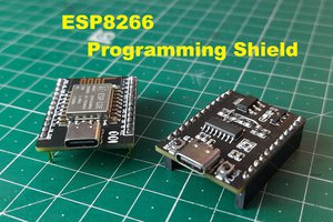
 Sagar 001