 Michael Gardi
Inspiration
I've been a vintage/retro computer enthusiast for a long time now and thought that I had a pretty good handle on all of the machines available in the 60s and 70s. So imagine my surprise when I saw the Kristina Panos February 23, 2022 blog post: INPUTS OF INTEREST: CANADIAN MCM/70 WAS KINDA LIKE THE FIRST CYBERDECK.
Wow. Mind blown. Here was a beautiful Canadian built personal computer from the mid 70s that I had no idea existed. As I read Kristina's post I became more and more intrigued. The MCM/70 was conceived by professor Mers Kutt of Queen’s University in Kingston, Ontario and was manufactured in Kingston. The company he formed to build the devices, Micro Computer Machines (MCM), was located in Toronto, Ontario. I live in Waterloo, Ontario, so all of this took place in my own back yard so to speak. Adding to that there was a ‘devastating power struggle’ between Kutt and some of MCM’s investors that in part ultimately lead to the demise of the company. Well I was hooked. Had to know more, had to have one.
Hardware
Based on the Intel 8008 microprocessor the MCM/70 had 32KB of ROM and up to 8KB of RAM. For output it used a Burroughs Self-Scan module, a 222 column by 7 row dot matrix display, capable of showing 32 5x7 dot characters at a time. Because the MCM/70 supported APL out of the box, the keyboard was based on the IBM 2741 layout. Finally up to two cassette decks were used for offline storage and to implement virtual memory.
Software
The MCM/70's operating system consisted of two modules EASY (External Allocation SYstem), and AVS (A Virtual System) which were built into the ROM. These allowed the user to directly interact with the machine. In addition the ROM contained an MCM/APL interpreter. From cassette, APL application libraries could be loaded for finance, mathematics, statistics, education, and games. There was also printer and plotter support software.
Research
Kristina's blog post was a good place to start learning about the MCM/70. It's a great summary of the origin of the machine, what it was, and its ultimate fate. I would encourage anyone with an interest in the MCM/70 to start there as I did.
For a more in depth look, the blog post references the book Inventing the PC: the MCM/70 Story by Zbigniew Stachniak. I purchased the book and really enjoyed it. A lot of the book is about the history of the company Micro Computer Machines which I found fascinating. More importantly, towards my goal of making an MCM/70, the book talks a lot about the design of the machine and provides insights into what ultimately led to that design some of which were technical, some practical, and some political.
After doing a little more digging I discovered that The York University Computer Museum (YUCoM) has an MCM/70 on display. York University is only about 110 kilometers from where I live, about a hour and a half's drive away. Cool. I also learned that the YUCoM has developed a historically accurate software emulator for the MCM/70 and is offering it free to anyone who requests it. So naturally I requested it through an online contact form and who should answer that request, Zbigniew Stachniak the author of Inventing the PC: the MCM/70 Story who also happens to be the curator of YUCoM. Small world. I hope to visit the museum in the near future now that COVID protocols are being relaxed.
I did some more in depth research into the MCM/70's display and keyboard as these would definitely be the "hard parts" to reproduce. I'll detail my findings in future posts, but I'll say for now that after that research I was convinced that the MCM/70 Reproduction project was feasible, and that I would be happy with the result. So let the fun begin.
The Game Plan
Look. I would like nothing better than to find a dusty old MCM/70 computer for cheap in some thrift shop and restore it to it's former working glory. Realistically we all know how unlikely this is given that relatively few MCM/70s were ever produced and that it has been close to 50 years since the last one was made.
So what about recreating the hardware from scratch. Obtain the original schematics and with luck PCB layouts, source the parts, many of which are vintage now and no longer manufactured, and make a replica. While this is might be possible, the endeavor would be very expensive, certainly well beyond the means of the average enthusiast like myself.
Another possibility is to create an emulation of the MCM/70 in software. This is just what the team at the The York University Computer Museum (YUCoM) did. From their web page:
An alternative approach to the direct use of MCM hardware is to write historically accurate software emulators of this computer destined for modern desktop and laptop computers. Although such emulators do not necessarily reflect the computer's hardware on, say, integrated circuit level, they offer a platform for research of general hardware organization, storage organization, systems and applications software, etc.
Software emulation is great and is certainly an important part of preserving these wonderful old machines, but I have found that nothing beats the feel of typing on a physical keyboard and hearing the sounds of the keys clicking.
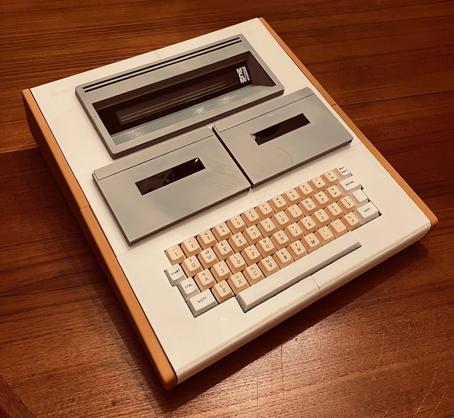
So here is where I come in. My plan is to make a full size MCM/70 computer reproduction with a real keyboard and display which I'll integrate into the YUCoM emulator. This physical reproduction will be as accurate as possible but made with modern components and fabrication techniques. For instance, the case will probably be 3D printed. I will add the cassette bays to give an authentic look but at least for my first out they will not be functional, instead using the emulator's virtual cassettes. Ultimately I will produce an Instructable so that others might make their own MCM/70 should they choose to.
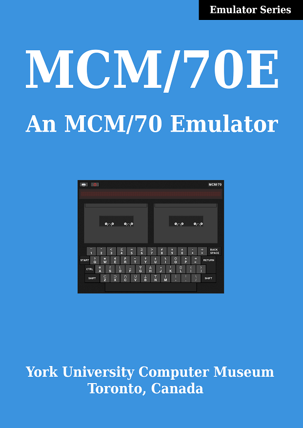
The York University Computer Museum MCM/70E Emulator
So thanks to the hard working folks at York University, I have a great head start with this project, a working MCM/70 Emulator. Not just working, but because it is intended for research purposes, an emulator "with high historical accuracy". From the MCM/70E web page:
In 2019, YUCoM offered its emulator of the MCM/70 as free software. The emulator is the result of an extensive study of the MCM/70 hardware and of a software recovery project that has preserved MCM software from approximately 100 digital MCM cassettes donated to the museum. It emulates the original MCM/70 hardware with 8Kbytes of RAM with high historical accuracy. In particular, the memory management as well as tape, keyboard, and display functionality are emulated accurately. The emulator operates under the original systems software and is using the original tape storage organization (reconstructed during the above mentioned software preservation project).
There is a great document, the MCM/70E Guide, that accompanies the software that tells you how to install and run the emulator.
MCM/70E is written in C and is available for Linux only at this time. It is delivered as source in a .tgz archive and must be compiled on the target machine. OpenGL and the GLUT utility toolkit are required for the emulator to compile.
My intention is to run the emulator on a Raspberry Pi 4. Unfortunately due to supply shortages it does not look like I will be able to obtain one in the near future (or maybe even longer). So in the interim I dug a Raspberry Pi 2 Model B out of my parts box to give the emulator a try.
I installed the latest Raspberry Pi OS (Version 11 (bullseye)) onto the Model B. I then downloaded and exploded the MCM70E.tgz file that I obtained from York University creating a /MCM70E_v2.1_distr folder. From within that folder I executed the following commands:
sudo apt-get install freeglut3-dev
apt-get install libncurses-dev
gcc mcm.c -lGL -lglut -o mcm
Notice that in order to get the emulator to compile under Raspberry Pi OS I had to install the ncurses library in addition to the GLUT library. Then it's a simple matter of running the emulator.
./mcm
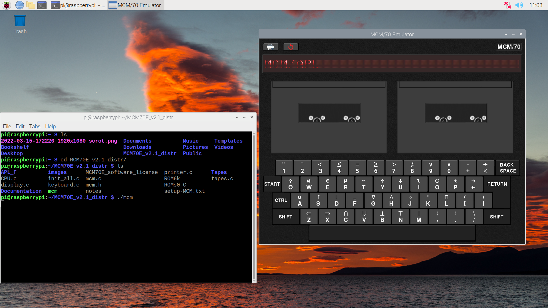
The emulator runs great with one caveat. On my Raspberry Pi 2 it only runs at about 20% of the speed of an actual MCM/70. At this point I am not too worried about that. On a Raspberry Pi 4 the emulation will run faster. Also I believe that much of the speed loss is due to the overhead of running OpenGL for the emulator's UI. When my reproduction is done there will be no need for the UI or OpenGL so I expect much better performance. If I'm wrong it's a problem for future me to resolve.
Update: I enabled the GL acceleration in Advanced Settings on the Pi but it made little difference. However adding the following gcc options (for the Raspberry Pi 2 specifically):
-mcpu=cortex-a7 -mfpu=neon-vfpv4
to the compile did improve the performance to be 33% of the speed of an actual MCM/70. I'm confident that further tweaks can get us up to par.
The Display
For output the MCM/70 used a Burroughs Self-Scan Model C4047 plasma display. These Self-Scan displays were an important stepping-stone technology between teletype terminals of the 1960s and the widespread use of CRTs from the mid-1970s on.
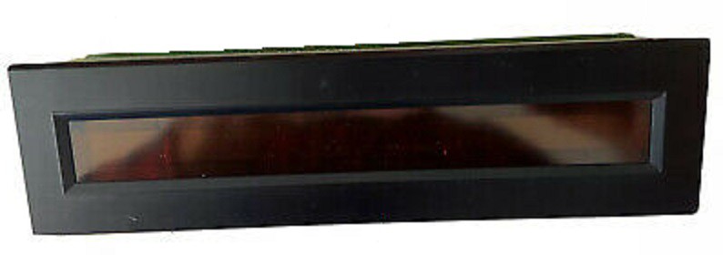
The display was arranged as a 222 column by 7 row dot matrix. An MCM/70 would use these dots to render 32 characters of 5x7 dots with two blank columns between each. Now a single line of text with 32 characters doesn't sound like much, but considering that the Altair 8800 released that same year just had front panel blinkenlights out of the box, it was quite a step up.
Here's the problem. These plasma displays are no longer manufactured. You can occasionally find one on eBay but they are pretty expensive. Even if I could source one, to tell you the truth the high voltages required for the plasma elements (250V) scare me a bit (even though I know the amperage is low).
So I spent a lot of time looking for a suitable replacement and think I found one, the Broadcom HCMS-2972.
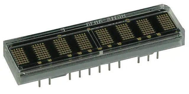
Packaged as 8 5x7 dot matrix arrays these modules operate at a nice safe 3.3V and can be cascaded together side by side to create the 32 x 1 character display desired here. Furthermore the viewing area for the 32 characters measures 171.7 mm x 4.57 mm while the Self Scan viewing area is 181.61 mm x 4.98 mm. So very very close.
There is one small drawback to using the HCMS-2972s. The Self-Scan displays form a full 222 x 7 dot matrix. When displaying characters however two columns between each character are turned "off". Four HCMS-2872s side by side are only 160 x 7 dots where there are physical gaps between the characters that happen to be about 2 columns wide. For normal use there will be no difference in the displays since the MCM/70 always keeps characters on a even 7 column boundaries. However when an MCM/70 is executing instructions that do not involve displaying outputs, it uses display memory to store temporary values. Since the hardware is constantly updating the display from this memory, random looking patterns of dots will be displayed. In my implementation these "thinking" patterns of dots will have blank columns between where the characters are. I think I can live with this.
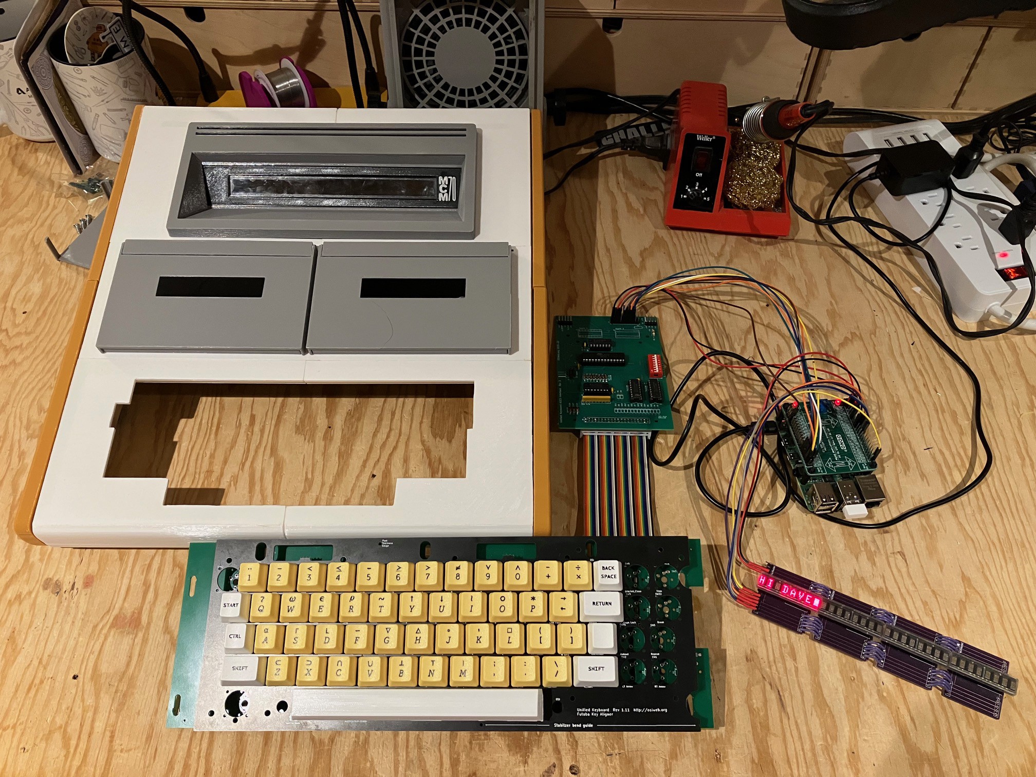
I received a HCMS-2972 earlier this week and setup quick test using an Arduino Nano I had kicking around. Here is what it looks like fired up.
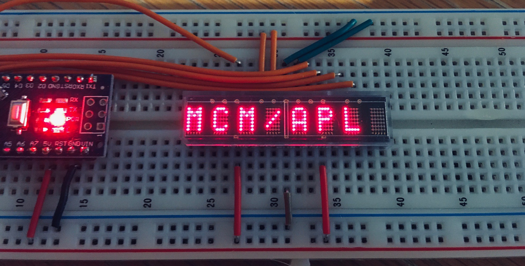
I have 3 more HCMS-2972s on order now.
The Keyboard
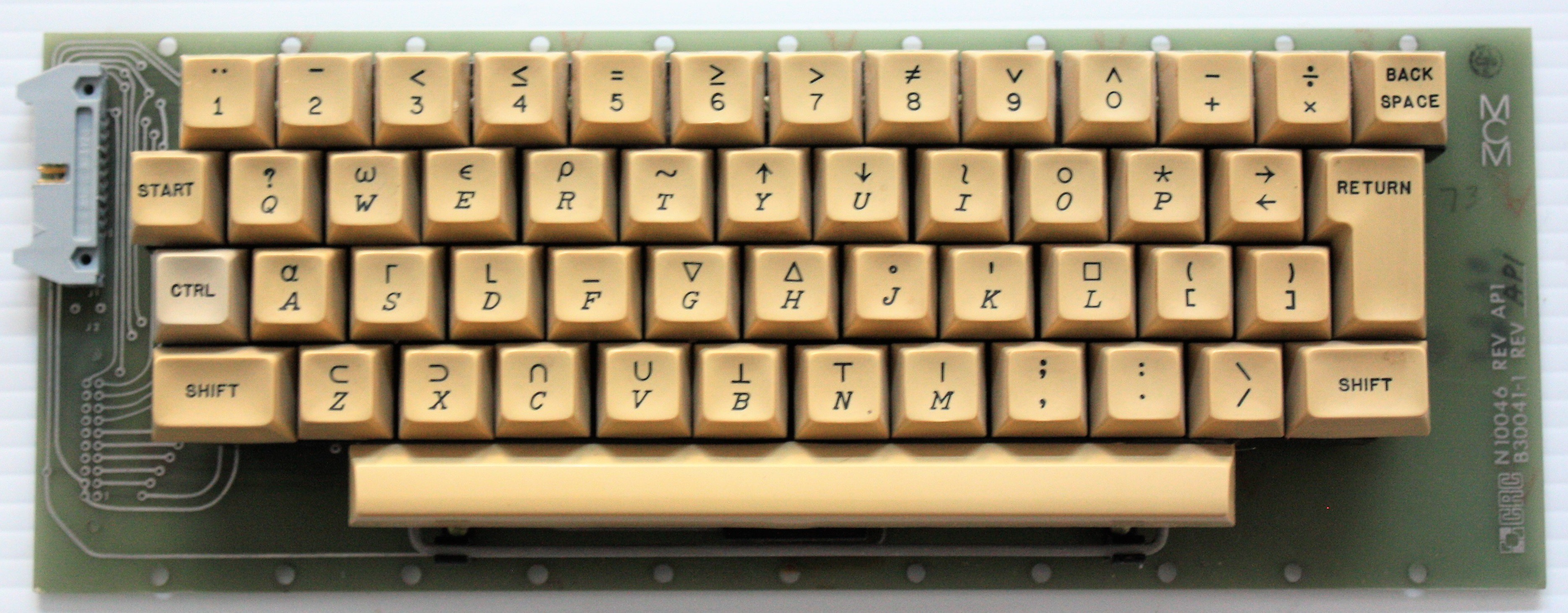
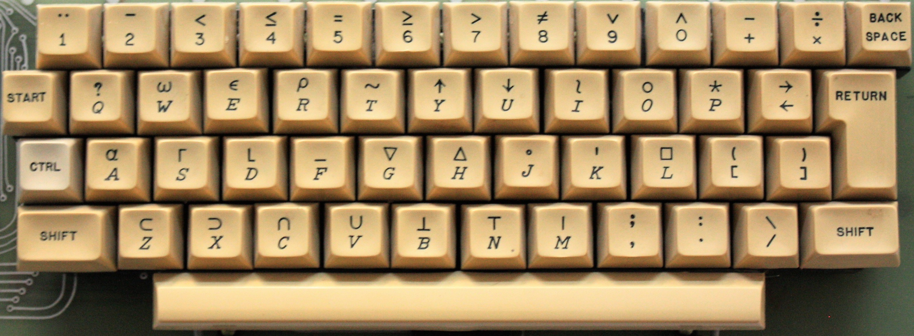
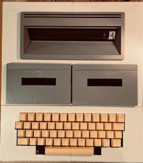
I knew that producing an authentic looking keyboard for this project would be a challenge in two parts. First getting the physical keyboard layout right with the MCM/70 keys. The second challenge will be to obtain a keycap set with the special APL symbols (legends). Here is an MCM/70 keyboard.
Well I think I have the keyboard layout issue sorted. After looking at many many keyboards online I found the following.
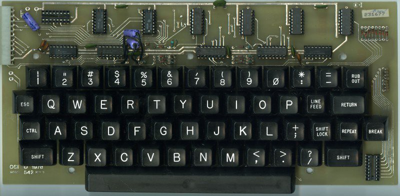
This is a keyboard for Ohio Scientific (OSI) computers that were popular in the mid to late 70s. It's a very close match layout wise to the MCM/70. One small difference is that the OSI spacebar is only 8U compared to the MCM/70's 9U size. Also the MCM/70 has an ISO style Return (rotated L shaped) key, but if you remove and ignore the OSI's Repeat and Break keys and replace the Return key with the ISO model it's a practically perfect replacement.
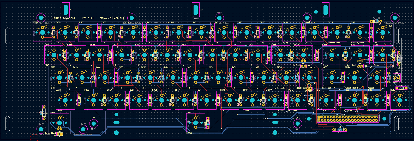
So how does this help? Aren't OSI vintage keyboards just as hard to find as MCM/70 keyboards? Well yes and no. Yes originals are hard to find, but thanks to Dave from osiweb.org replacement keyboards are not. I used Dave's Sol-20 reproduction keyboard for my Sol-20 Reproduction and it worked out great. If you check out Dave's Unified Retrocomputer Keyboard Project on GitHub you will see that he also offers keyboards for Apple I, Apple II/II+, Generic ADM/3A teletypes, and most importantly to me OSI computers. So I have ordered an OSI keyboard PCB and stabilizer, OSI keycaps, and an encoder.
As for the MCM/70 APL keycaps, well I'm still looking into that. Lots of options. More later.
Display Carrier Board
I have received all four HCMS-2972s, so it was time to start thinking about how to organize them into a 32 x 1 character display. My original thought was to design a PCB to hold all four parts. Then I realized that JCLPCB is going to ship a minimum of five boards anyway, so I came up with a carrier board for a single HCMS-2972 that can be easily daisy chained together with others.
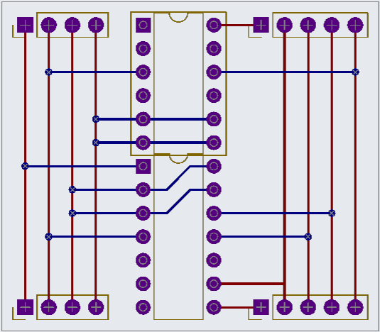
Pretty simple. I'll use a couple of IC sockets a 14 pin and a 12 pin to hold the HCMS-2972s in place (these parts are like $60 a piece so I'm not taking any chances with them).
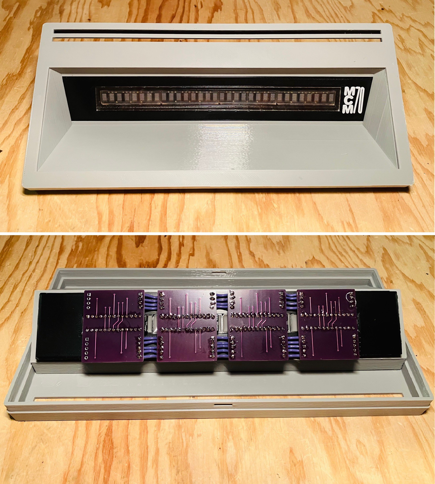
Based on the Broadcom HCMS-2972 parts and the display carrier board PCBs that I made, I have a working MCM/70 display.
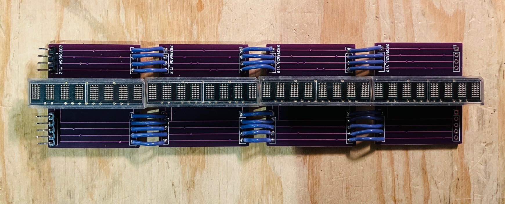
The carrier boards worked out great. Just had to wire them together.
With the display in hand, I was able to integrate it with the York University MCM/70 emulator. I used the Wiring Pi library to access the Raspberry Pi's GPIO pins. In order to make the library available for use I executed the following commands on the Pi with the emulator software installed.
git clone https://github.com/WiringPi/WiringPi.git
cd WiringPi
./build
The library is referenced in the code through the WiringpPi header file.
#include <wiringPi.h>
Also when building the code the wiringPi library needs to be referenced.
gcc mcm.c -lGL -lglut -lwiringPi -o mcm
When I'm a little further along I'll post the changes I made to the York University code. The HCMS-2972s are pretty easy to work with.
Here is a short video of the display assembly in action.
I had hoped to tackle the keyboard next but I will be a few weeks until I get the OSI keyboard PCBs. Hopefully I can get a start on the MCM/70 case.
York University Computer Museum Visit
Last week I had the pleasure of visiting the York University Computer Museum (YUCoM). I was greeted by Zbigniew Stachniak (Ziggy), curator of the Museum and author of the book "Inventing the PC - The MCM/70 Story". The museum is about an hours drive from my home in Waterloo Ontario.
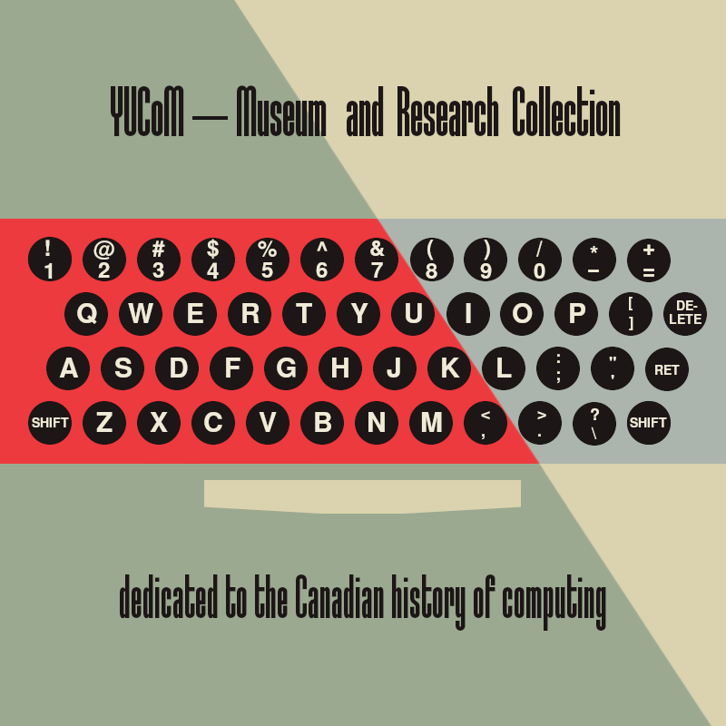
As the above poster indicates the museum specializes in Canada's contribution to the computing field.
The museum has a small selection of their large archive of Canadian computers on display. Since I was interested in the MCM/70 I first focused in on some of the other MCM models that they had on display.
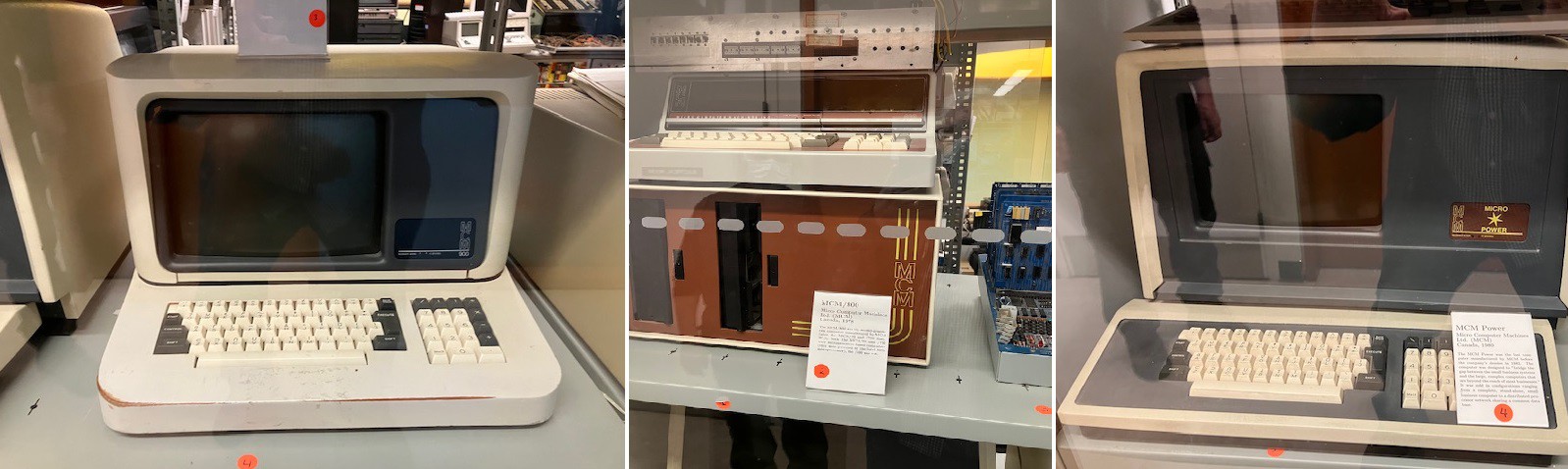
From left to right: MCM/900, MCM/800, and an MCM Power.
There were a few other exabits that caught my eye.
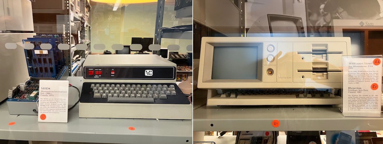
On the left is a computer based on the MIL 8008 microprocessor, a Canadian version of the Intel 8008. In the middle is a very early Volker-Craig terminal. VC terminals were manufactured in Waterloo and designed by a couple of University of Waterloo grads Michael C. Volker and Ronald G. Craig starting in 1973. They were very popular at the University of Waterloo when I was there (1977-1982). On the right is a Hyperion, an early portable computer thought to be the first portable IBM PC compatible. It was marketed by Infotech Cie of Ottawa.
After a brief tour I got down to business taking a good look at the MCM/70 on display.
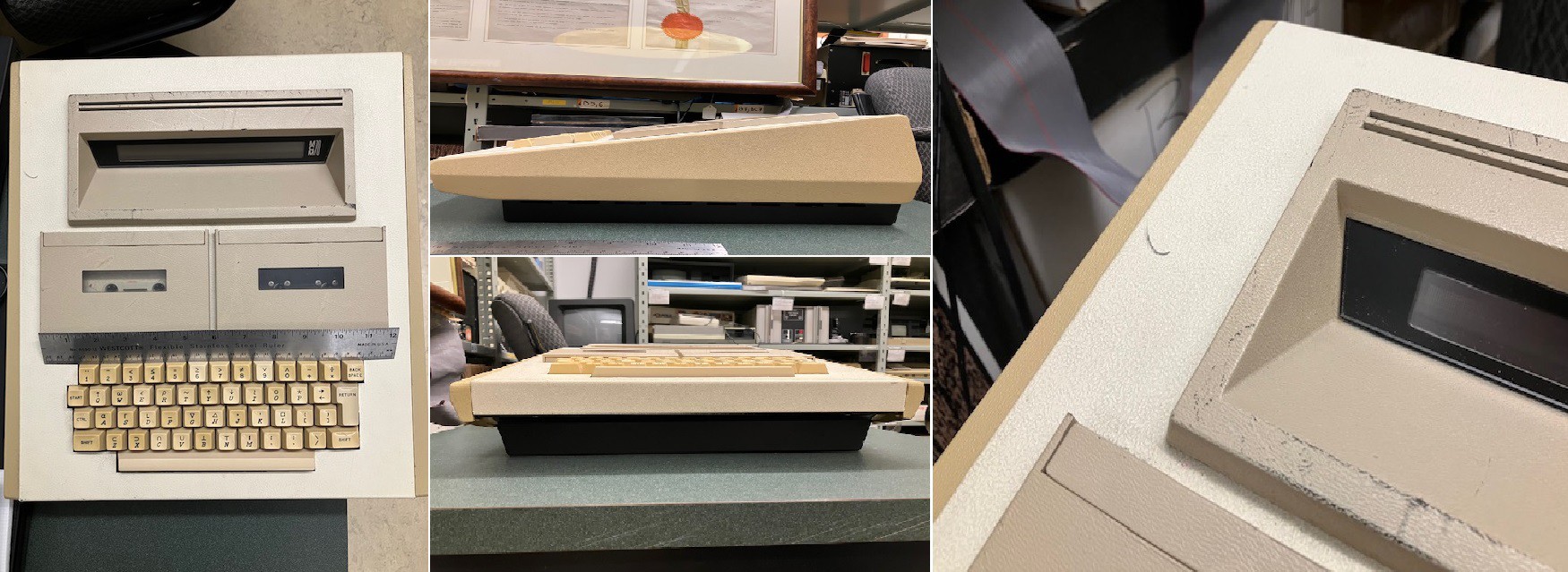
I took many photos as I would be modelling the MCM/70 case based on them. One surprise was that the side panels, which I thought to be made of wood, are actually injection molded. I would never have realized this had I not had access to the real thing.
While I was taking my pictures Ziggy and I had a great talk about the machine; he is probably the world's leading expert on the MCM/70. I especially enjoyed our conversation about the emulator that he wrote for the MCM/70. Since the intent is to use the emulator for research purposes he spent a lot of time making sure that it worked precisely as the hardware did. Since he had a couple of MCM/70s available to him he was able to validate the emulator's faithfulness to the original. We were also able to compare emulation techniques since I wrote an emulator for a Sol-20. Nothing like spending an afternoon geeking out ;-)
So now I have what I need to get going on the MCM/70 case. Ziggy has graciously offered to provide more information should I require it. I foresee spending a lot of time working with Fusion 360 over the next couple of weeks.
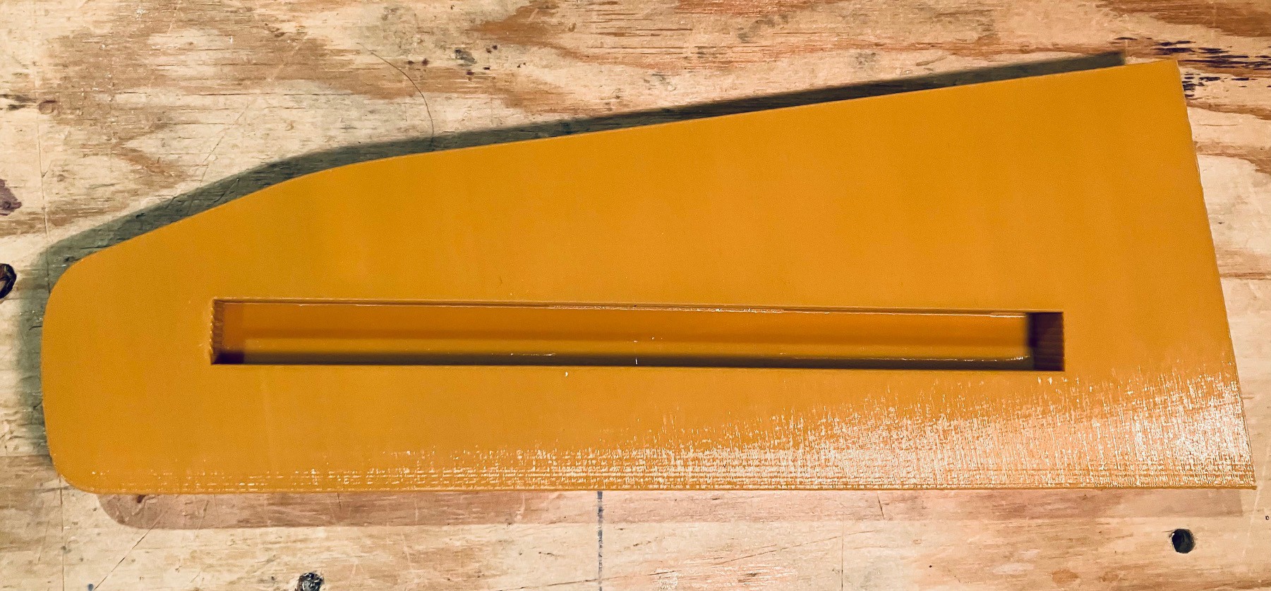
Side Panels
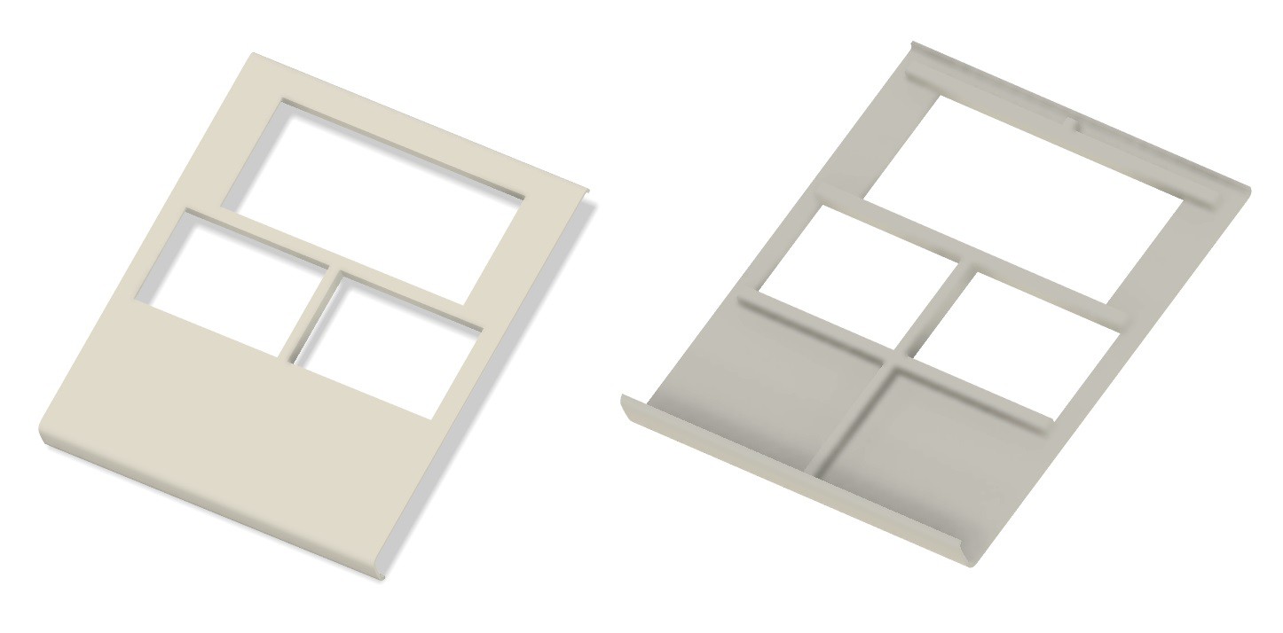
I mentioned that to my surprise the side panels for the MCM/70 were injected molded plastic, so I decided to 3D print them. It took a bit to get the models to my liking based on the photos I had, but in the end I was happy with the results. Here are my models.
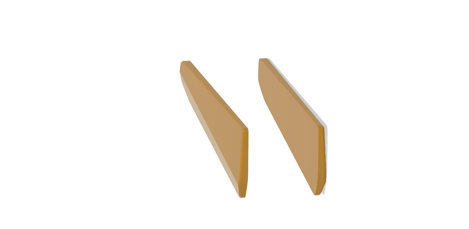
And this is what they look like printed.
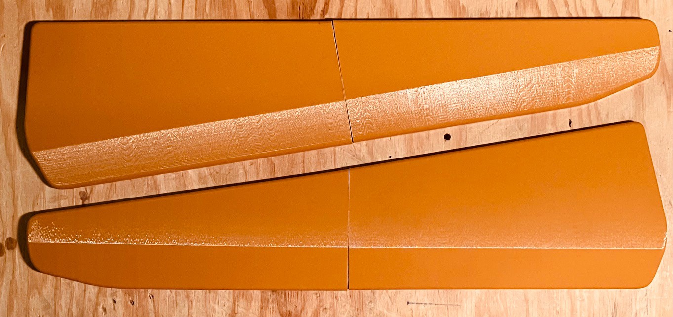
Time to start putting together a frame.
Display Assembly
Finished the display assembly. It's ready to pop into the case when that's done.
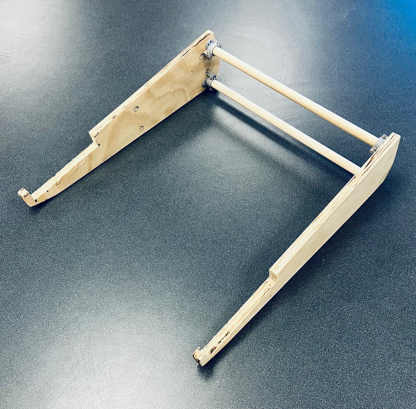
The Frame
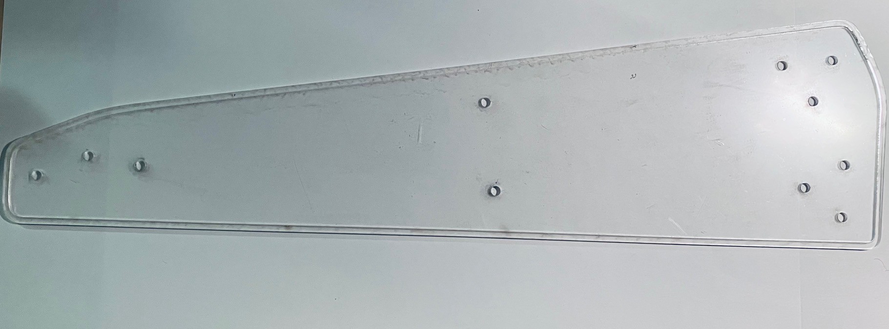
I created a template to cut out the "in"side panel pieces for the MCM/70
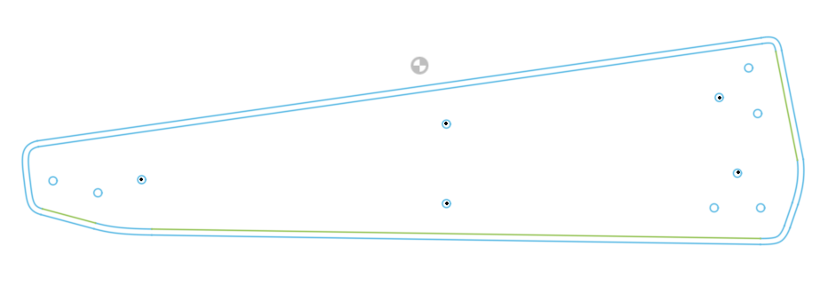
frame. The outside line represents the side panels as printed, while the inside outline is 3 mm smaller and is used to make an inner frame to support the top panels. Holes indicate positions where screws (#6 x 3/4 inch) will be used to attach the printed side panels to the inner frame (black dots), and attach flanges for 1/2 inch doweling to the inside frame (#6 x 1/2inch screws). I laser cut the template from a scrap of acrylic I had lying around to use as a positioning guide for the screw holes.
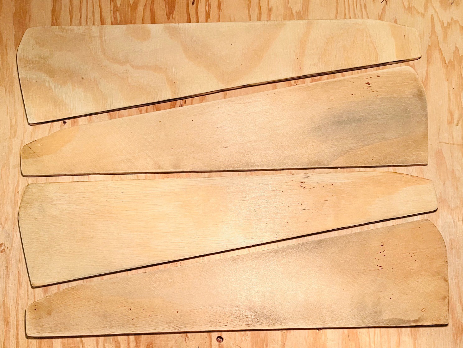
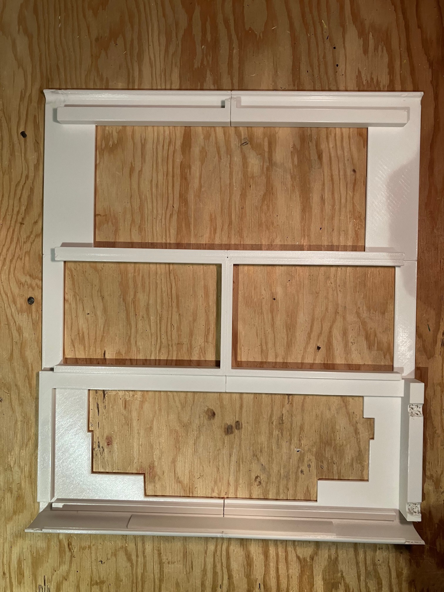
Then I laser cut four of the smaller pieces from 6 mm plywood.
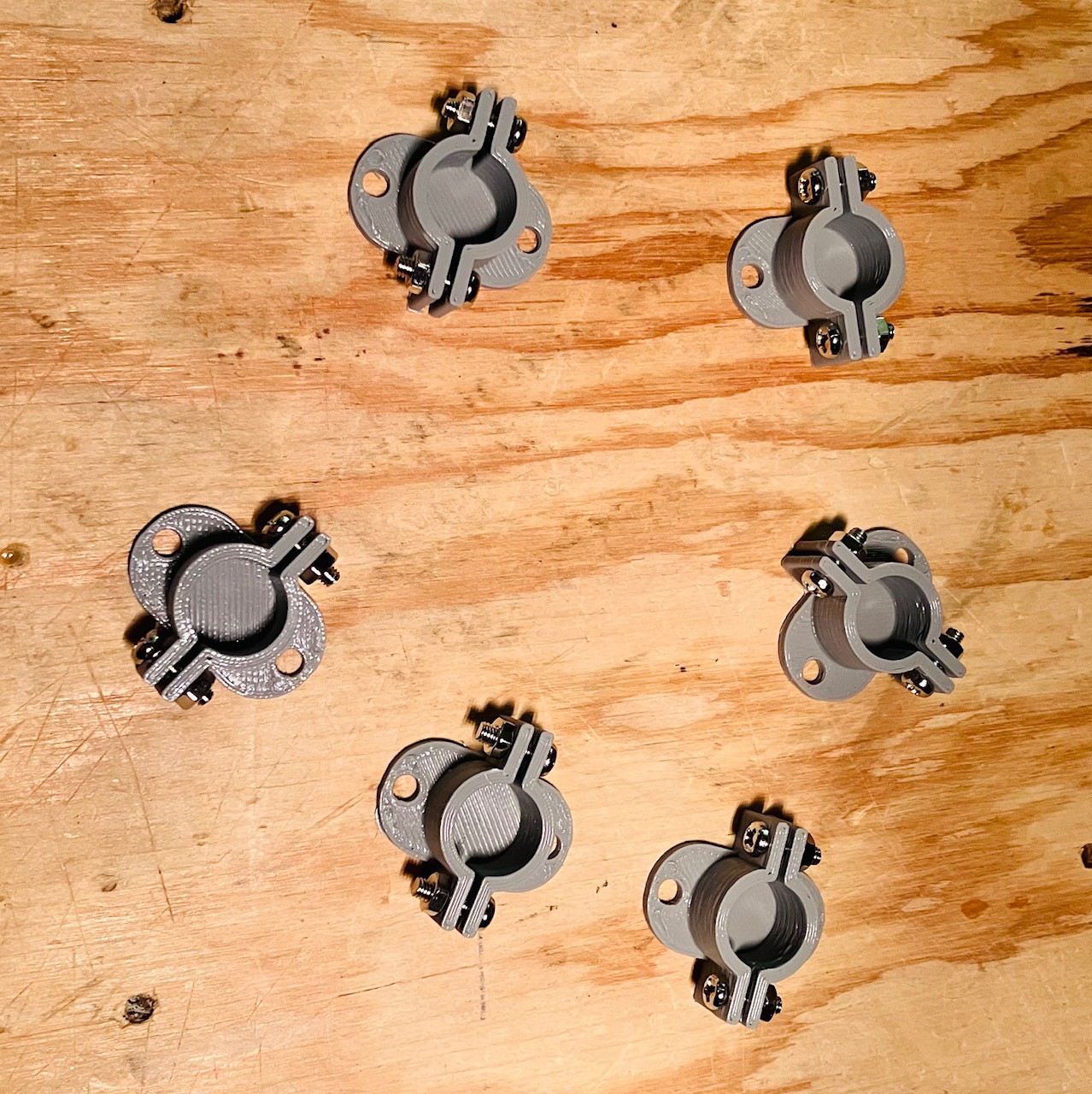
I designed and printed six flanges to anchor 1/2 inch dowels.
Then I glued two panels together for each inside frame and mounted the flanges based on the template.
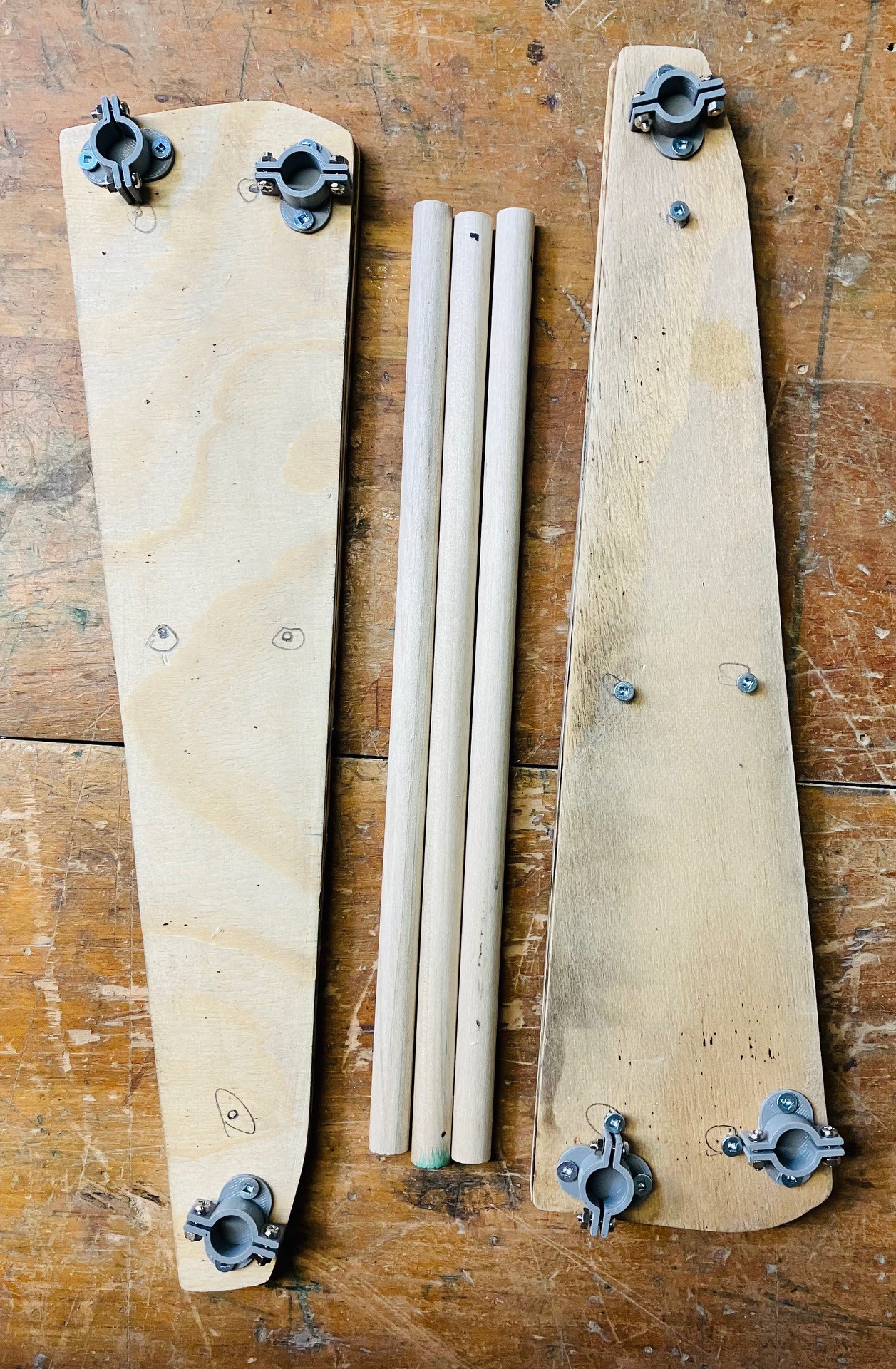
The dowels were cut so that the width of the machine from the outside edges of the inner frames is exactly 13.25 inches just as it is in the original. I attached the printed side panels to the inner frame pieces and inserted the dowels.
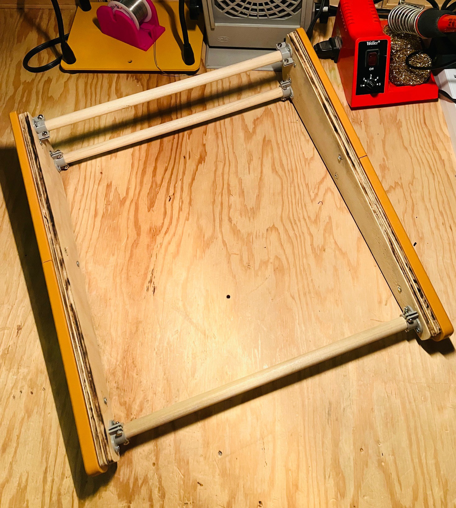
So I now have a solid frame to which I will mount the rest of the MCM/70 components.
Placebo Cassette Decks
So I'm adding fake cassette decks to my MCM/70 reproduction and you might be wondering why. Couple of reasons.
First of all the YUCoM software that I am using emulates a machine that has two cassette decks. When I visited the the York University Computer Museum Zbigniew Stachniak (Ziggy) mentioned that MCM did ship a model with no cassette decks (and one with a cassette deck and a modem), but that without cassettes the machine was basically just an APL calculator. So I could have saved some time and still been historically accurate I guess.
More importantly though, virtually all of the online images of the MCM/70 feature the two tape deck model. It's important to me that my reproduction is clearly recognizable as an MCM/70 so placebo cassette decks it is.
Here is the result of my efforts.
Based primarily on this photo and the measurements that I took at the museum.
I even got the tape eject lever working ;-) I still have to laser cut the acrylic windows for the lids.
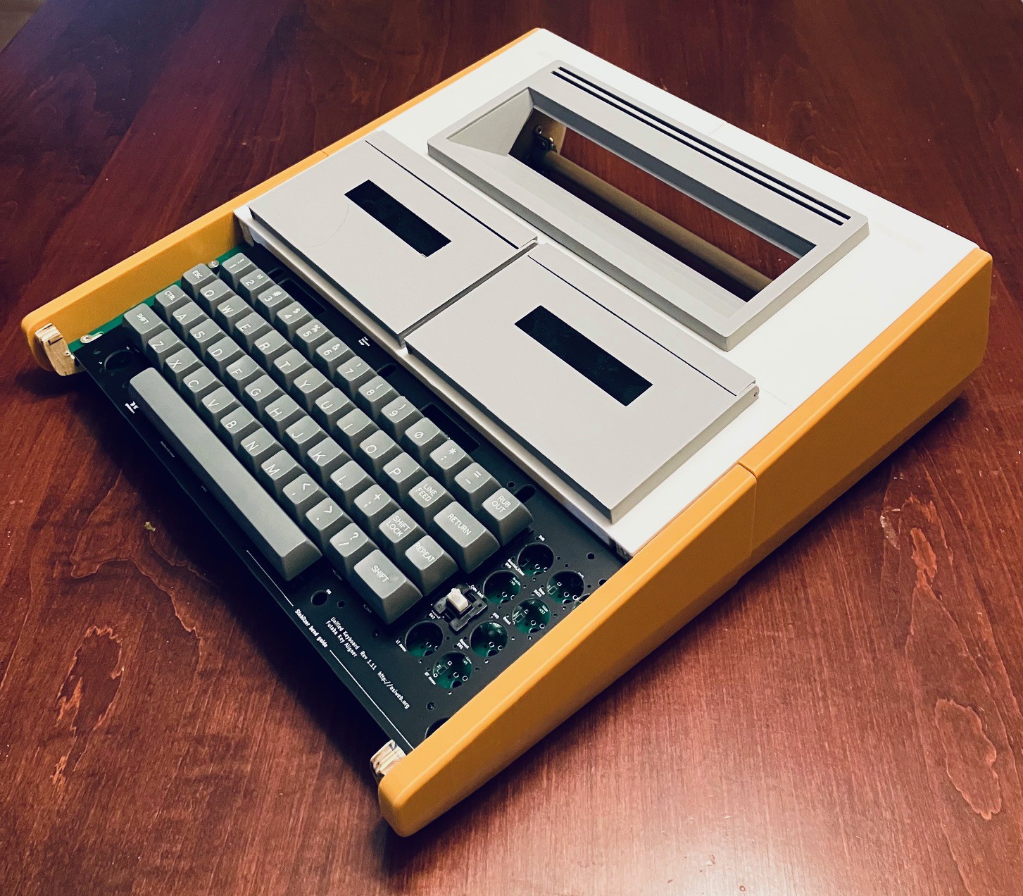
Top Panel
With the frame built it's time to add the top panel. First I modeled the panel in Fusion 360. Notice that I don't have a cutout for the keyboard yet because I don't have the keyboard yet.
I have added integrated support "beams" to the underside. Since this model is way to big for my print bed I used 3D Builder (which I believe ships with all current Windows versions) to cut the model into six pieces. The Split tool in 3D builder is easy to use and works great.
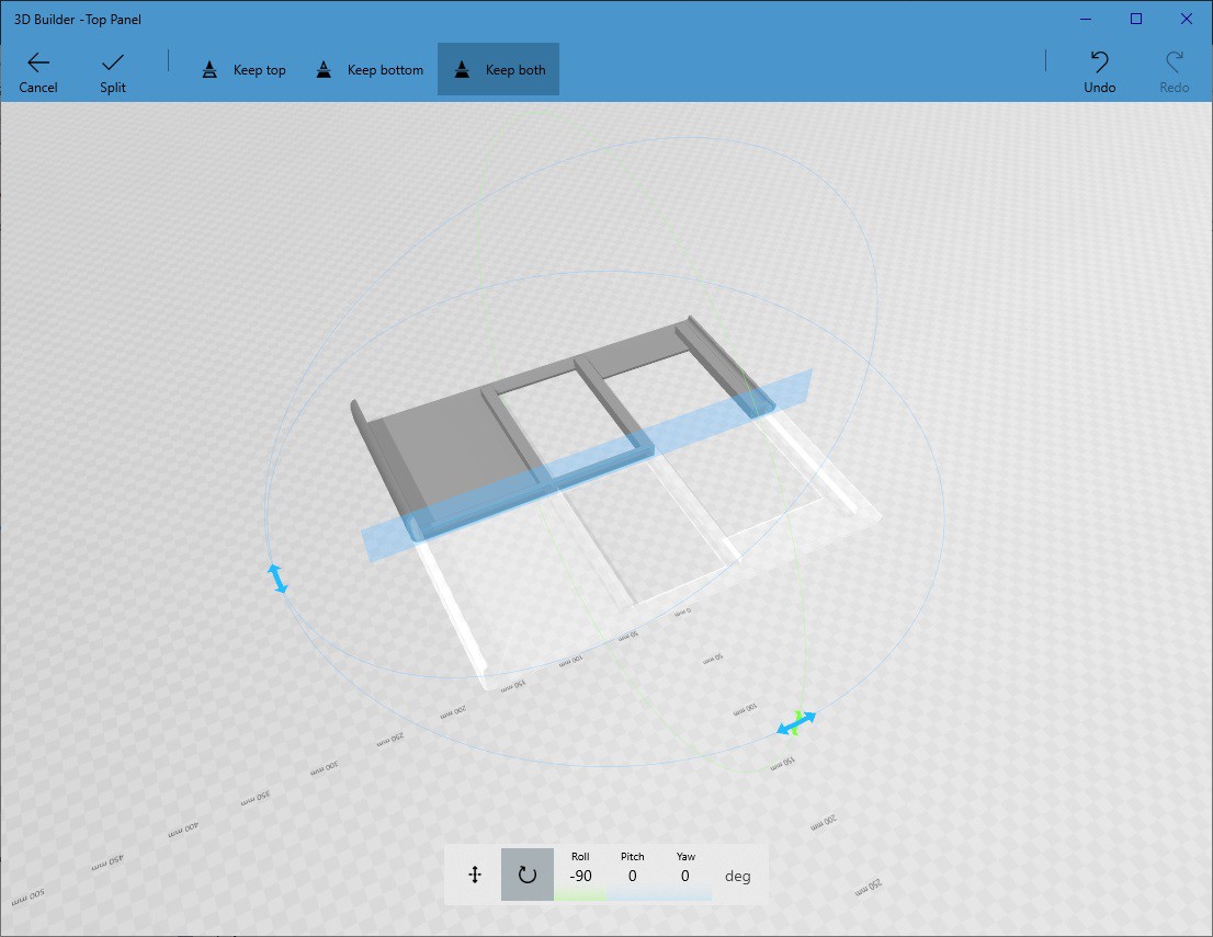
I did all of the splits down the centerline of the vertical and two center horizontal beams so that I would have a lot of surface area when gluing the pieces back together.
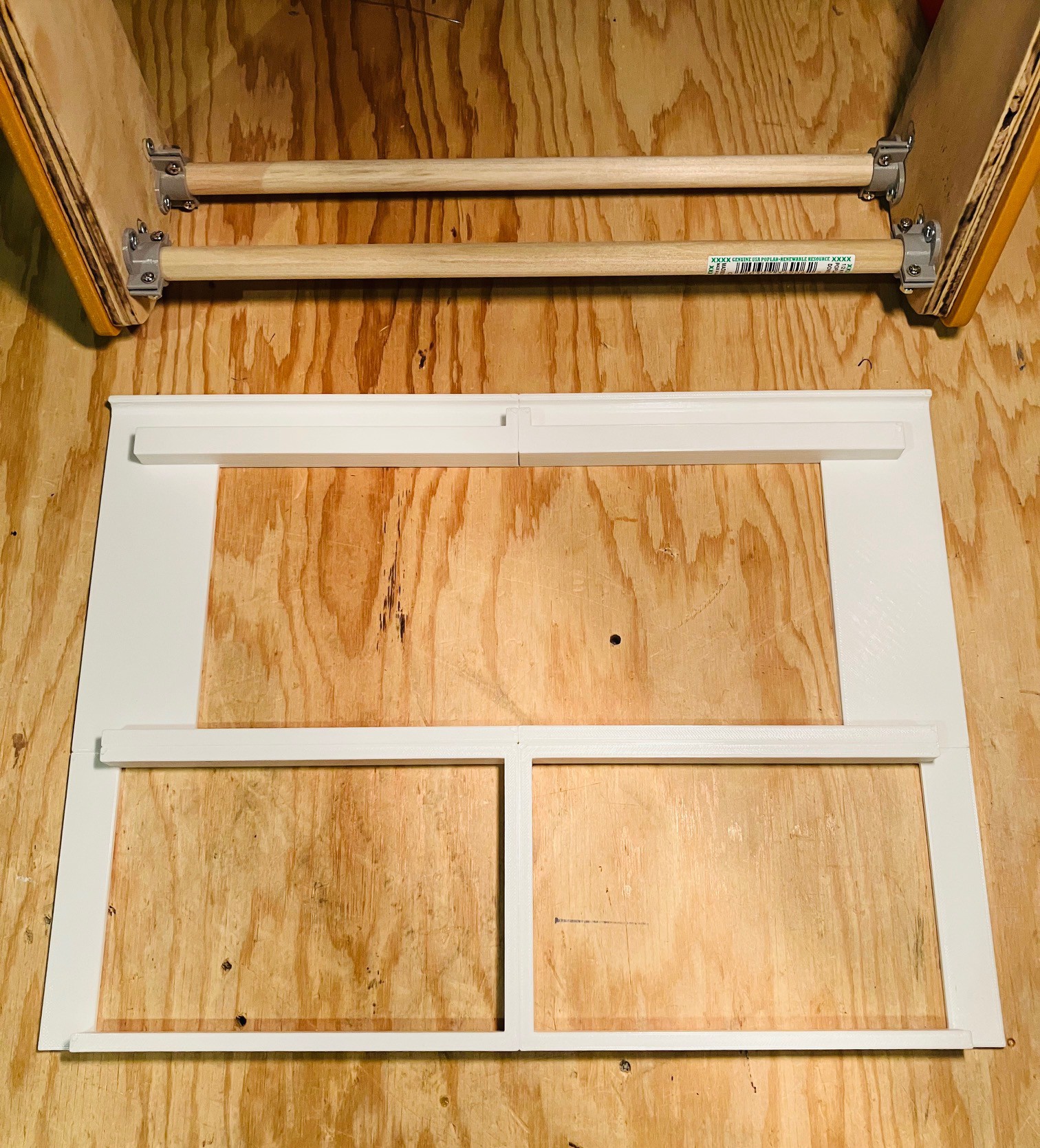
So far I have printed and assembled the top four panel parts. I used a gel CA glue to attach the pieces together. I printed the top panel in white because I could not find a suitable pale yellow filament. I have seen images where the panel appears to be white but that could just be due to the lighting when the photo was taken. I'm not opposed to painting the top panel at some point closer to the end of the project.
And this is what it looks like so far with the display and cassette drives installed.
Hoping for Some Legendary Keycaps
To say that the MCM/70 keyboard is unique would be an understatement. Because it supports APL out-of-the-box there are twenty plus keys that have special shifted characters like α and ∆. Not to mention that the more standard special character keys are in different places than on a modern keyboard. Plus I don't know if I've ever seen italicized letter key legends .
Believe it or not you can still purchase APL keycaps, like this set from UNICOMP (for a pretty reasonable $35).
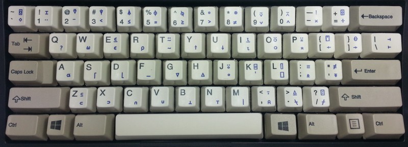
While there appears to be a standard APL layout for the keys, the key legends look quite different. So I'm resigned to having to make my own keycaps. But how?
After doing a bit of research I thought there were four potential options:
- Purchase. A number of vendors will now allow you to submit SVG files with your keycap legends and produce the keys for you.
- Laser Etching. While directly etching the legends onto a keycap has not worked very well, DIYers have had success by coating the keycap surface with print toner or dye sublimation ink then using laser etching to fuse the glyphs to the surface. Once done the excess toner or ink is washed away.
- Dye Sublimation. Key legends are printed (reversed) with special dye sublimation ink. The glyphs are then positioned directly on the keycap and transferred by applying heat (400 F - can be accomplished with a hair curler) and pressure.
- Waterslide Decals. Key legends are printed on special waterslide paper and transferred by first soaking them in water then sliding the clear top layer with the glyph and some adhesive to the keycap.
These are arranged for the most part in easiest/cheapest to hardest/most expensive order. So my plan is to start at 1. and keep trying these methods in order until I get a result that I'm happy with.
Regardless of the method that I use, I need to have the key legends defined. To that end I have used Inkscape to create SVG versions of the legends that can be scaled to fit the keycaps. Here is what they look like.
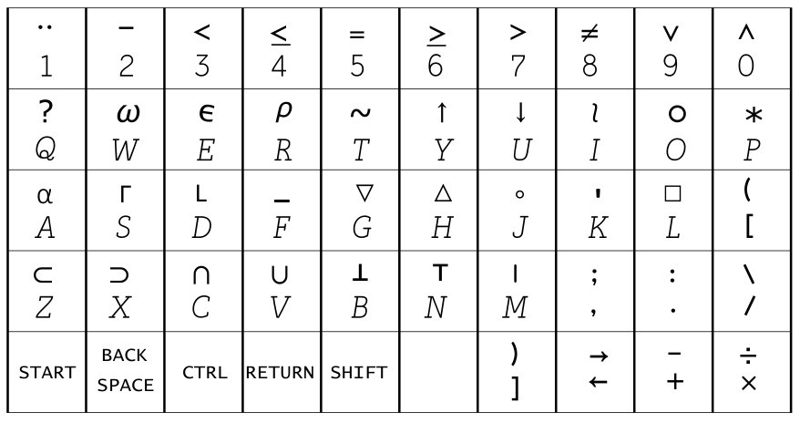
Still needs a bit of work but a pretty good start.
Rejoice the Keyboard Has Arrived
I've kind of been in a holding pattern waiting for the keyboard "kit" to arrive but no more as it was delivered this week. This is a classic retro-style ASCII keyboard, modeled after the ADM-3A keyboard, which can also be populated to fit perfectly in an Apple II/II+, or an Ohio Scientific Inc. computer, or as it turns out an MCM/70. For details check out the Unified Retro Keyboard project.
I was able to purchase the keyboard PCB, a set of Futaba MD-4PCS keys, a stabilizer panel for the Futaba keys, and a keyboard encoder card from Dave from osiweb.org.
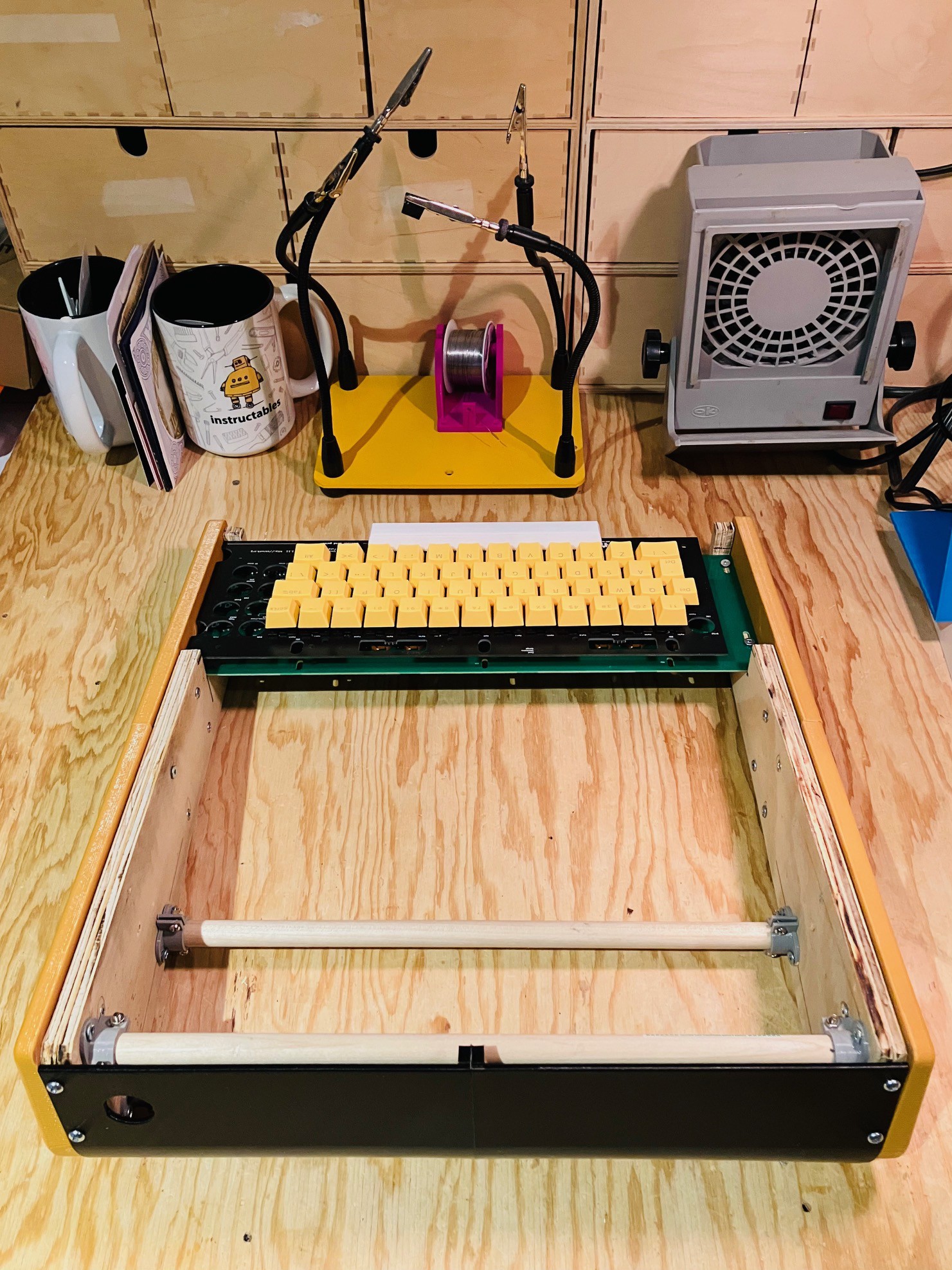
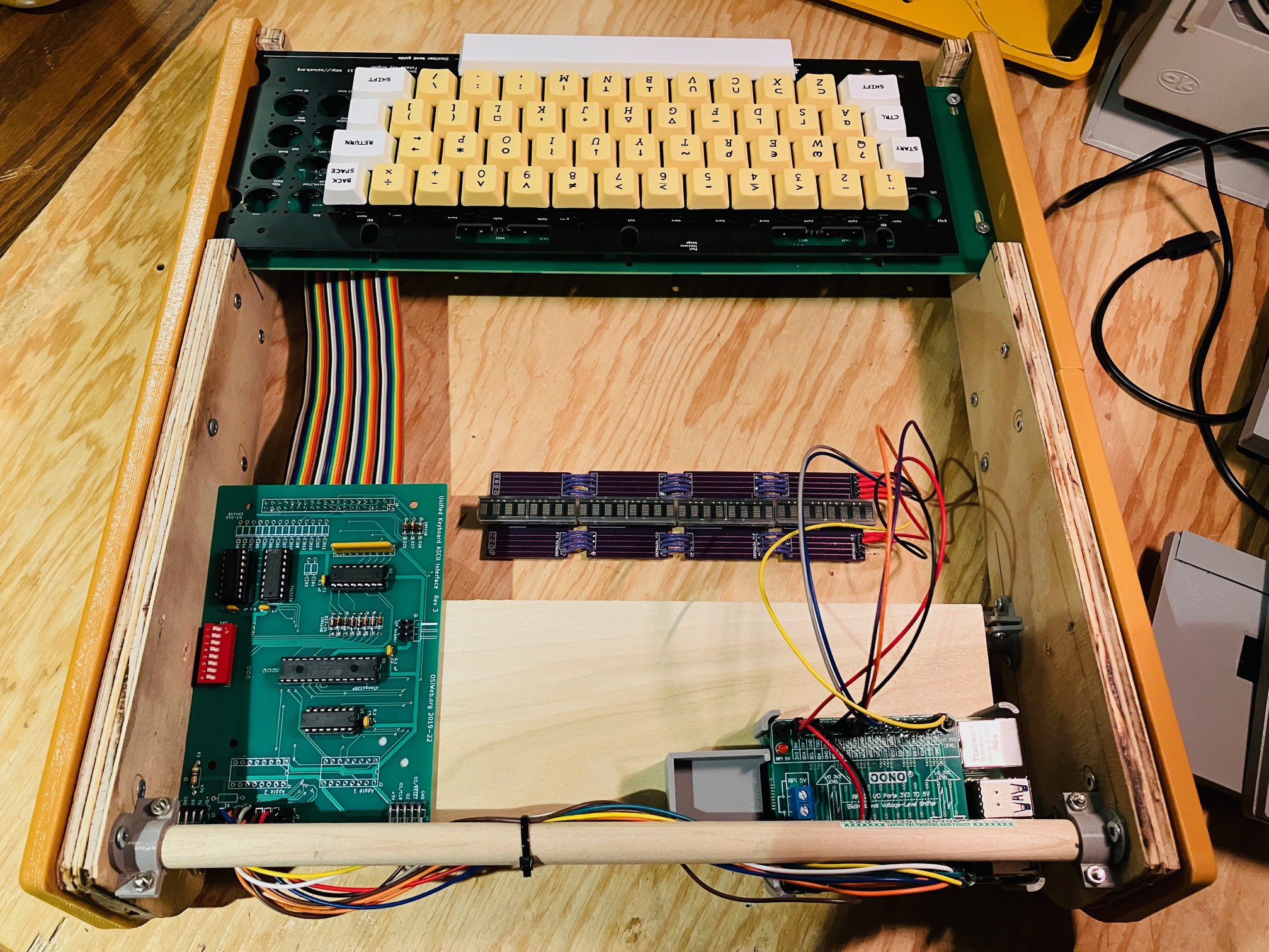
The first thing I did was to set the keyboard PCB with a few keys loosely set in place onto the partially finished MCM/70 case to get a rough feel for what it would take to integrate the keyboard.
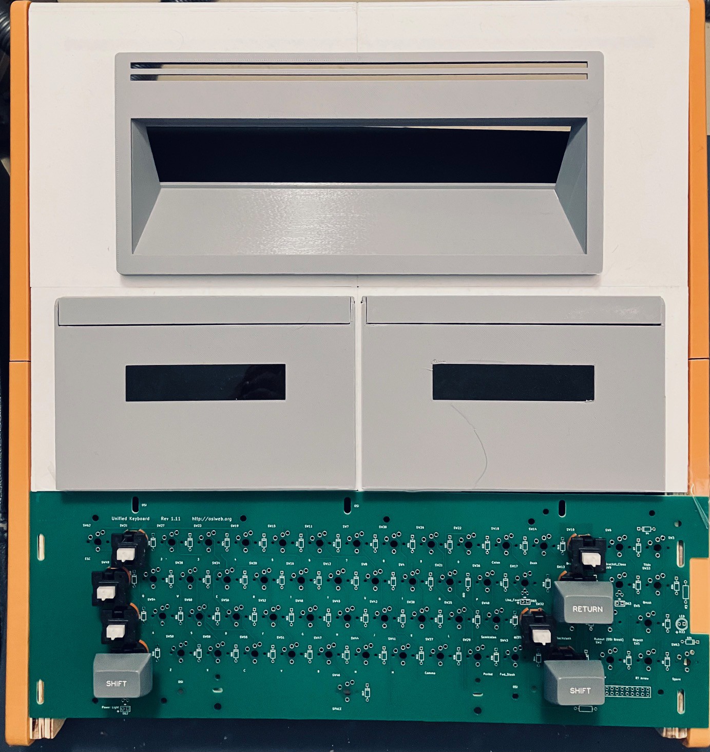
I was happy to see that while it looks like a tight fit, I am sure that I can make it work. So with some confidence I went ahead and assembled the encoder and keyboard. I'm not going to detail the process here since it was mostly identical to the work I did on my Sol-20 Reproduction. For details check out:
- Keyboard Construction (Note that the newer keyboard PCB has the discrete diodes and resistors pre-populated on the board. A real time saver. Thanks Dave.)
- The Keyboard Encoder
Here they are.
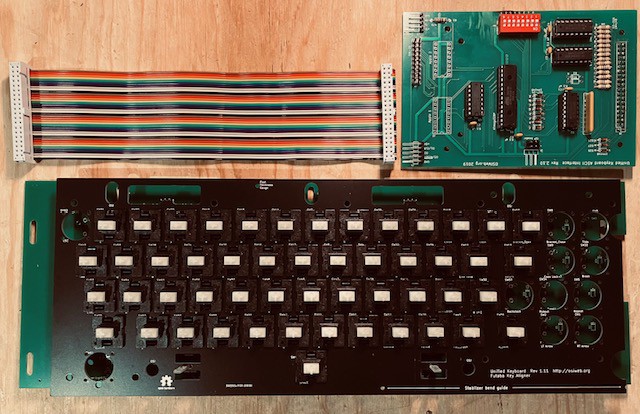
By design the encoder can be mounted onto the back of the keyboard via the 40-pin headers. This is what it looked like for the Sol-20.
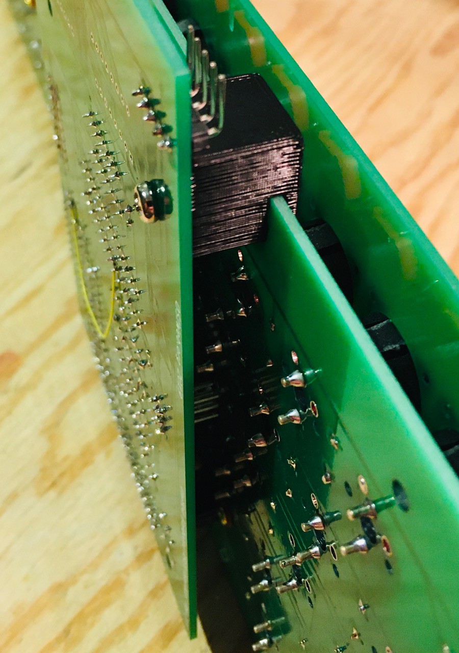
However there is not enough room in the MCM/70 case, so I am going to use the ribbon cable pictured above.
Next testing.
Installing the Keyboard
Today I integrated the keyboard into the frame I have constructed. The first thing I did was to remove the front most dowel and cut a notch in the side panels to accommodate the keyboard.
Now I'd like to brag that I was thinking ahead about how the keyboard would be attached when I built the frame, but the truth of the matter is that I got very lucky that the width of the original MCM/70 happens to work out perfectly with respect to the mounting holes in Dave's keyboard.
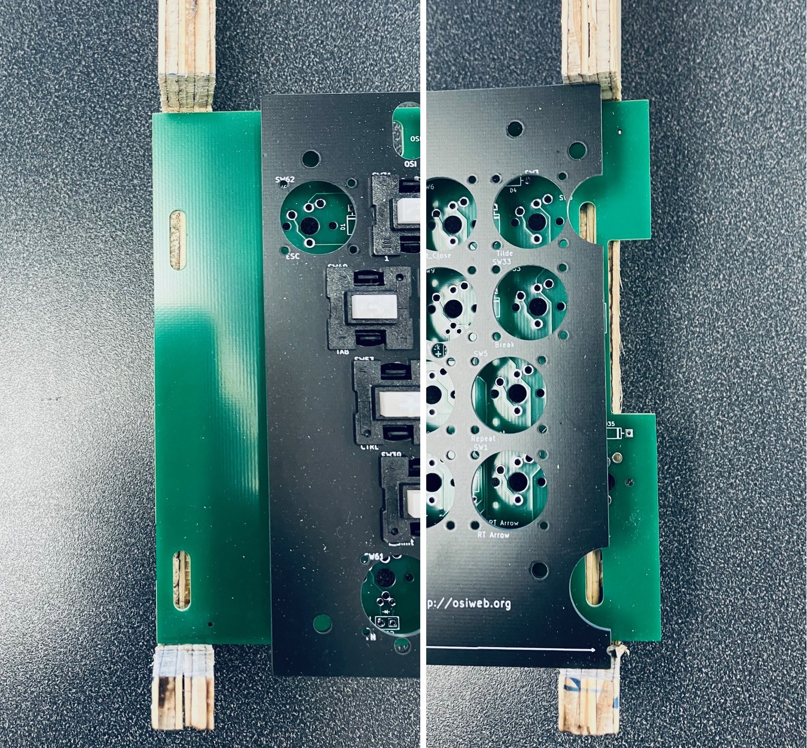
The only issue here is that the keyboard PCB sticks out a bit past the right inner side panel. So I screwed down the keyboard, re-attached outside side panels, and set the top case panel in place.
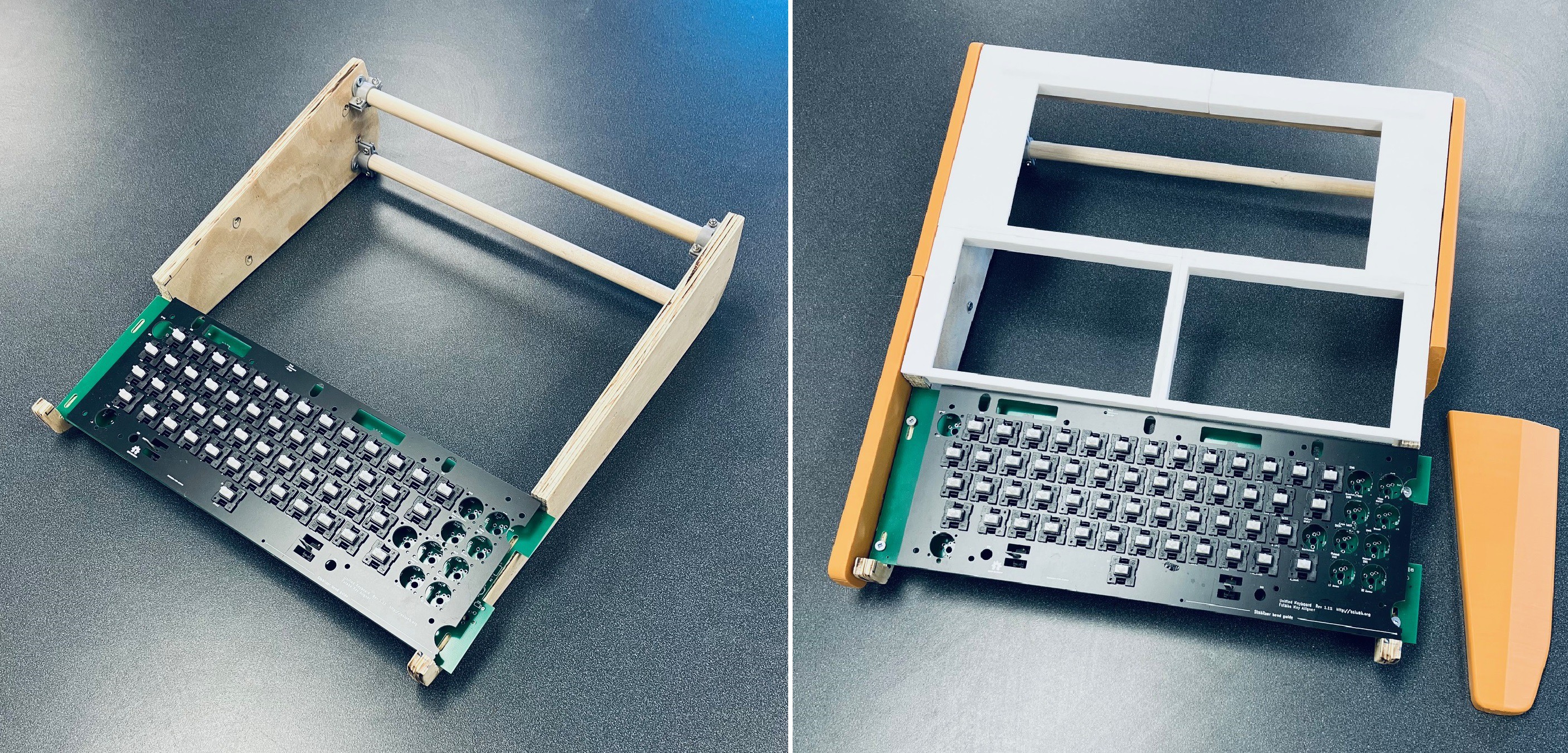
Of course the right outside side panel will not go on because of the keyboard sticking out. I'll correct this by reprinting that part with a slot to accommodate the protruding keyboard PCB. So I printed a new side panel with a slot to accommodate the protruding keyboard PCB.
I was able to reattach the side panel and mount the keyboard. For the moment I have attached the keyboard from my Challenger 1P project as it already has the keycaps installed and the layout is almost exactly the same as for the MCM/70.
I can now start to model the final keyboard piece of the case skin.
Keyboard and Display Integration Test
With the keyboard and encoder assembled it was time to test. First I had to make changes to the York University MCM/70 emulator. I took the opportunity to switch away from the Wiring Pi library to access the Raspberry Pi's GPIO pins. Wiring Pi has been deprecated so I am now using the pigpio library for both the display and keyboard GPIO access. Pigpio is installed by default on Raspberry Pi OS.
The library is referenced in the code through the pigpio header file.
#include <pigpio.h>
Also when building the code the pigpio library now needs to be referenced.
gcc mcm.c -lGL -lglut -lpigpio -o mcm
It was an easy change since the API calls are very similar.
Here is a short video of the display and keyboard in action. A couple of notes.
- When the MCM/70 is "calculating" you will see random dots on the display. This is because the machine was severely memory constrained so display memory was used when the display itself was not required.
- The keycaps I am using are not the final ones. This was a cheap set I got from Amazon because the color was a pretty good match. I am in touch with a couple of companies that make custom keycaps to hopefully get more accurate reproduction keycaps.
- The emulator is now running on a Raspberry Pi 4. Much faster than the model 2 I was using. In fact the timing test from the MCM/70 Emulator manual ( 0.7 ÷ ι255 ) runs in about 18 seconds. On the original hardware this test runs in 50 seconds. There is a setting so the emulator can be slowed down to match historical speeds. Check out the video.
I have printed the case cover for the keyboard area. Again these are not the final keycaps so the spacebar in particular shown here is 6U while the original's was 9U.
Needs a bit of "fit and finish" but getting close.
Wiring
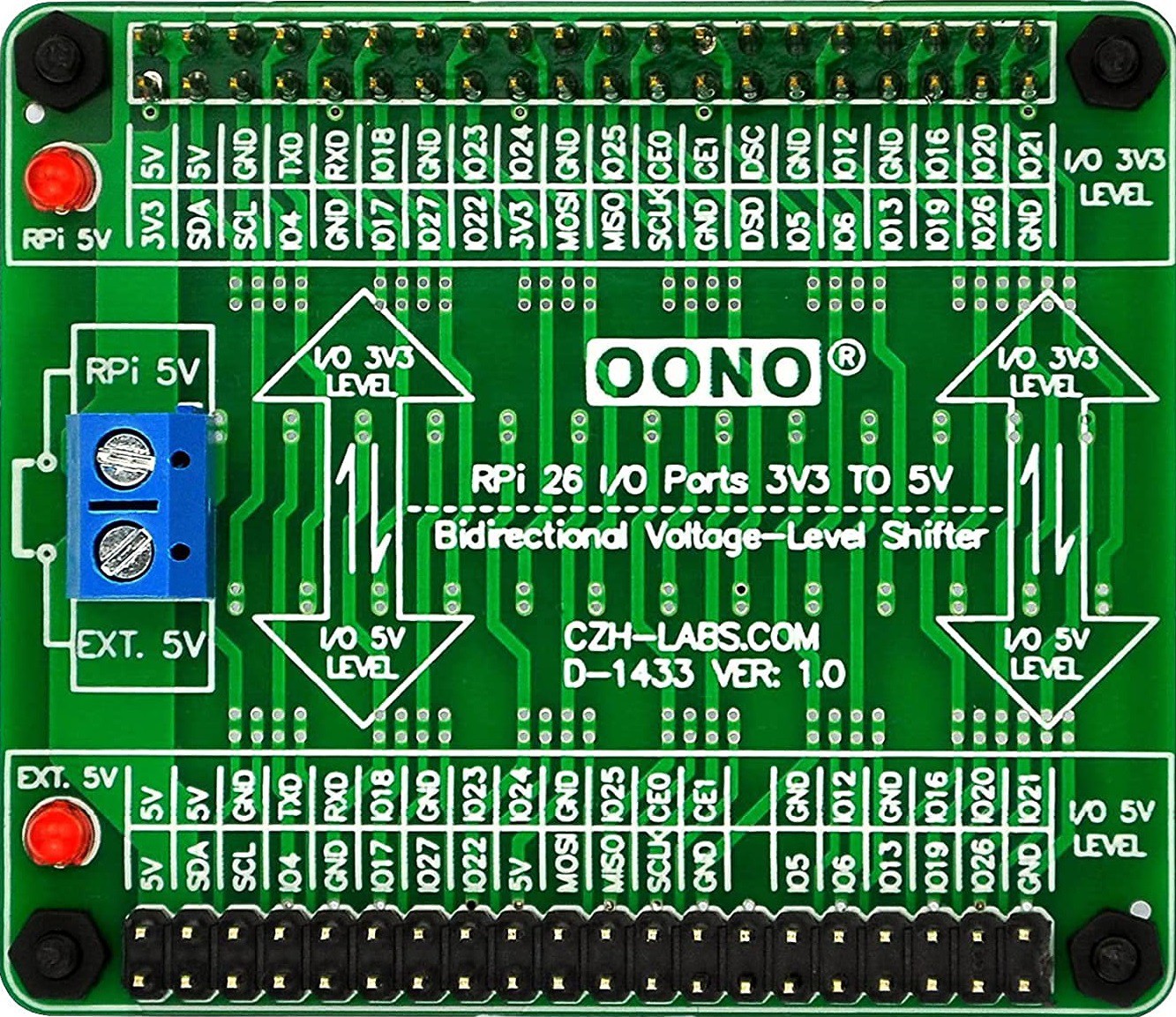
As with my Sol-20 project, the keyboard encoder is expecting 5V while the Raspberry Pi 4 operates at 3.3V. So to overcome this I purchase a Voltage-Level Shifter Module from Amazon. Here is what it looks like.
I am using the Sol-20 header on the encoder and the pinout looks like this.
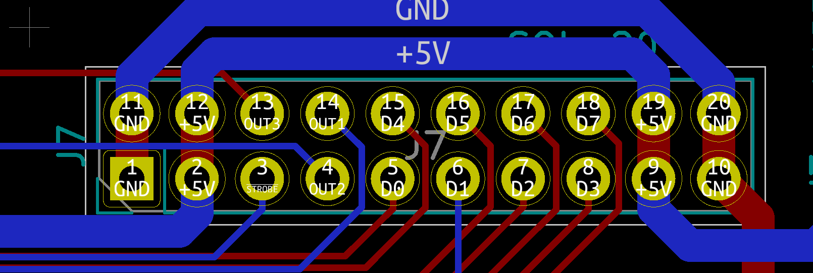
So here is how I wired the keyboard. Note that for the exception of +5V and GND lines which are wired to the 3.3V side or the level shifter, all of the other connections are wired to the 5V side.
| Keyboard Encoder | Raspberry Pi | Description |
|---|---|---|
| +5V | 5V | Power |
| GND | GND | Ground |
| D0 | GPIO5 | Key 0 bit (low) |
| D1 | GPIO6 | Key 1 bit |
| D2 | GPIO12 | Key 2 bit |
| D3 | GPIO13 | Key 3 bit |
| D4 | GPIO19 | Key 4 bit |
| D5 | GPIO16 | Key 5 bit |
| D6 | GPIO26 | Key 6 bit |
| D7 | GPIO20 | Key 7 bit (high) |
| STROBE | GPIO4 | Key ready on falling edge. |
The display has the following pinouts.
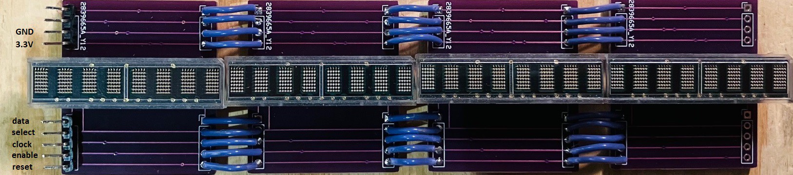
All of the following connections are wired to the 3.3V of the level shifter.
| Display Module | Raspberry Pi | Description |
|---|---|---|
| 3.3V | 3.3V | Power |
| GND | GND | Ground |
| data | GPIO21 | Data Pin |
| select | GPIO22 | Register Select Pin |
| clock | GPIO23 | Clock Pin |
| enable | GPIO24 | Chip Enable Pin |
| reset | GPIO25 | Reset Pin |
Next step, mount everything into the case.
Finishing the Case
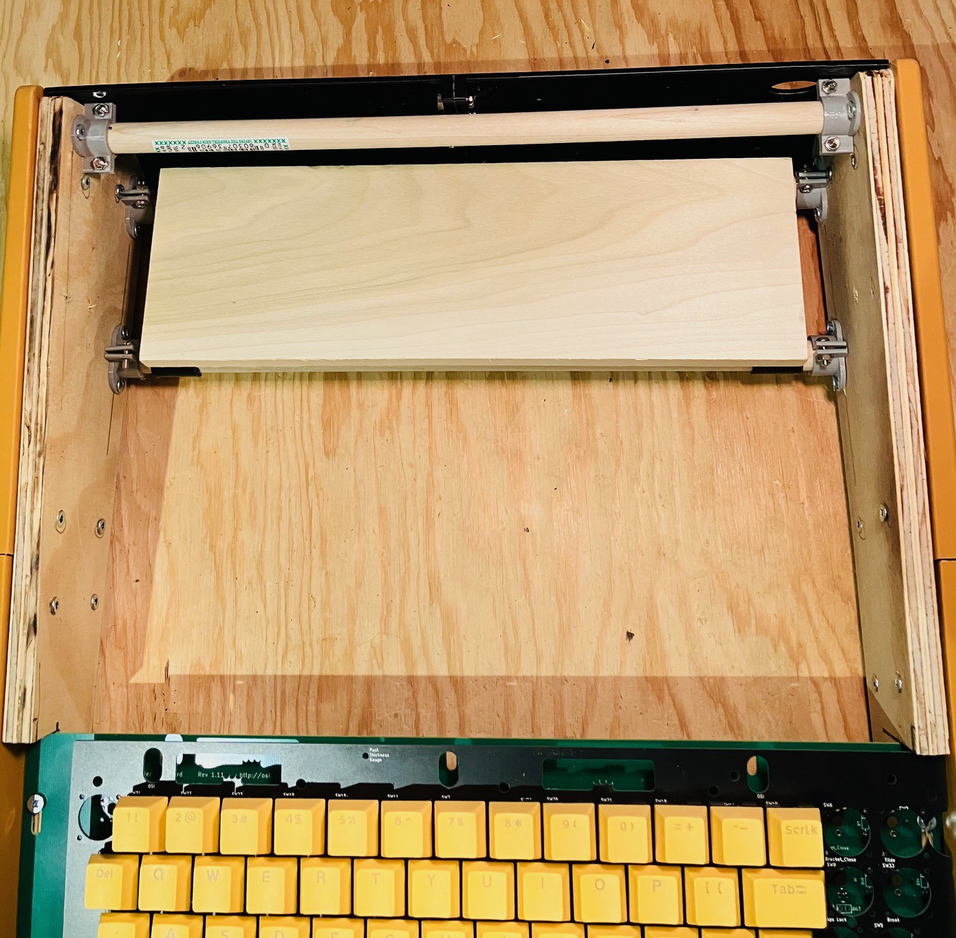
So with the major components of the project completed and tested it's time to start putting it all together. The first thing I did was to put the dowel and flanges that I removed from the front of the case (to make room for the keyboard) to the rear of the case level with the existing bottom dowel.
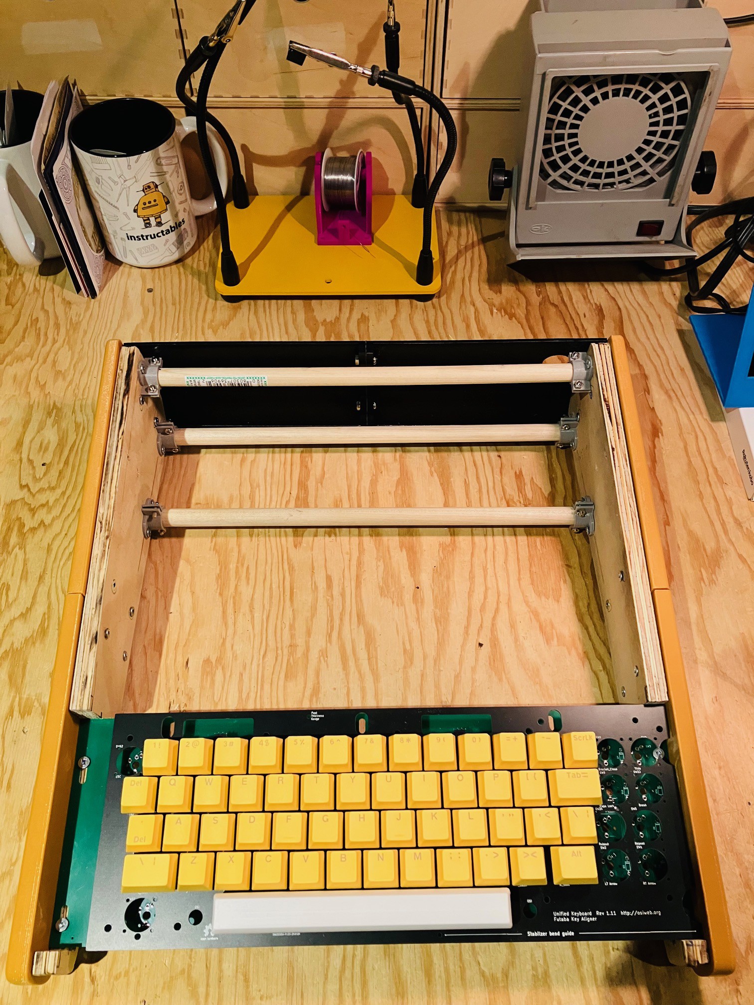
I cut a piece of 1/2 x 4 inch pine to size and attached some printed brackets in order to mount the board to the dowels.
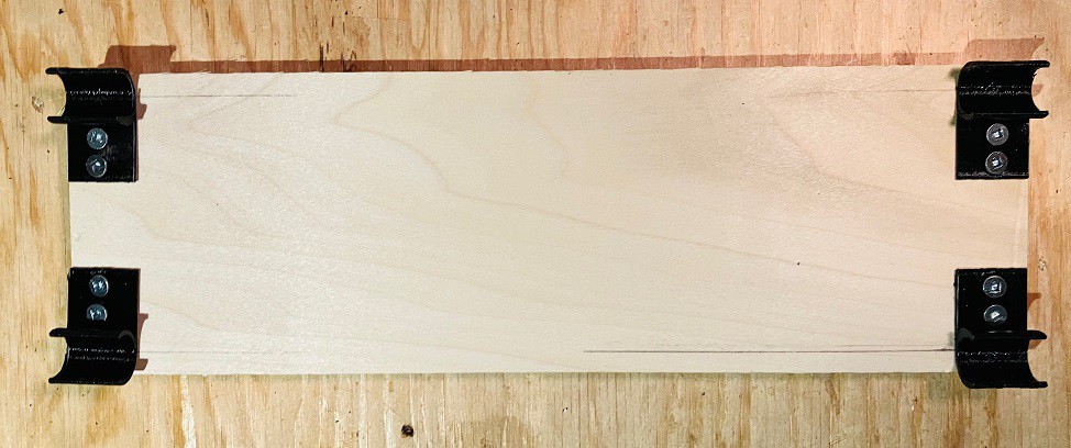
This will give me a platform to mount the Raspberry Pi 4 and the keyboard encoder.
You might have noticed that I also modeled a back panel for the case.
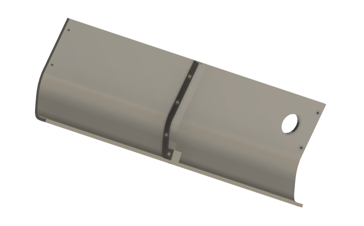
The original back panel had a fuse, a printer connector, lots of screws, and other details.
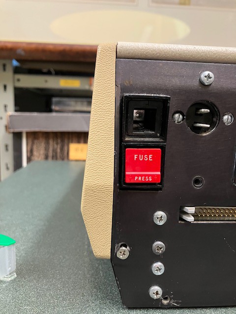
I decided for my reproduction to keep things simple and did not follow suit. One reason is that the original MCM/70 sat on a black box that extended down below the sides. At this point I don't think I'm going to do that. On most of the pictures you see of the MCM/70, the black box bottom is never really shown. In fact I didn't even know it existed until I visited the York University Computer Museum and saw an original (pictured below).
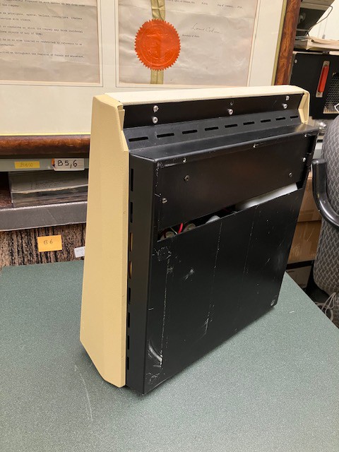
I might revisit this down the road but I have to admit I like the nice clean look of my reproduction without the bulky bottom.
I attached the keyboard panel to the top panel with a good CA glue and added a brace to the front part of the panel.
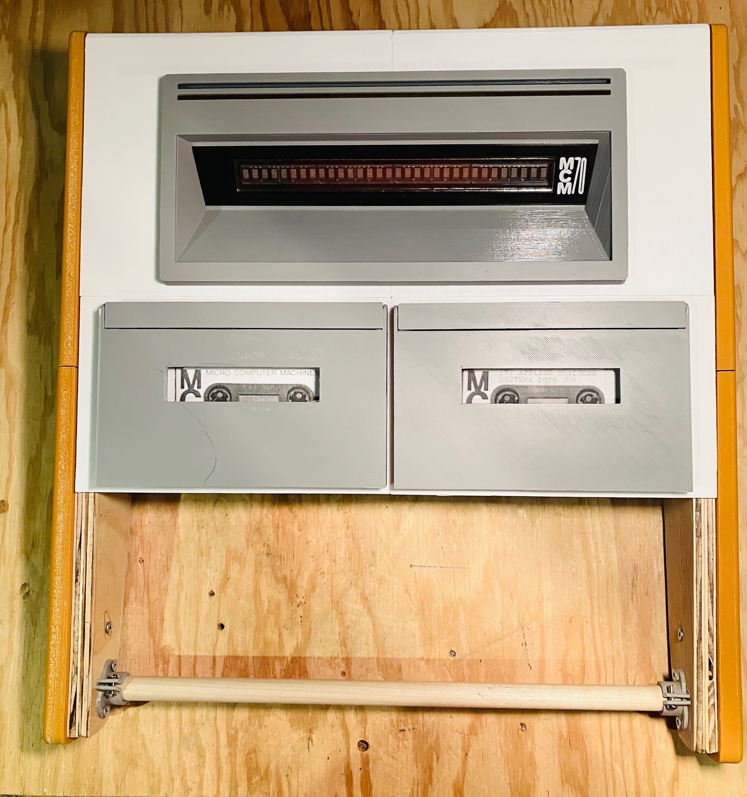
Putting it all together with the tape drives and display this is what you end up with.
Almost there! The keycaps pictured above are still the cheap ones from Amazon. I have ordered custom keycaps from KROME Keycaps. They have been great to work with and the order is in transit from Great Briton. I'm very excited to see the result.
Also note that I have not been able to track down an 8U or 9U spacebar in yellow or even white. So I modeled and 3D printed the one you see above. I'm pretty happy with the result. Here is what it looks like compared to the 8U spacebar from the OSI keyset.
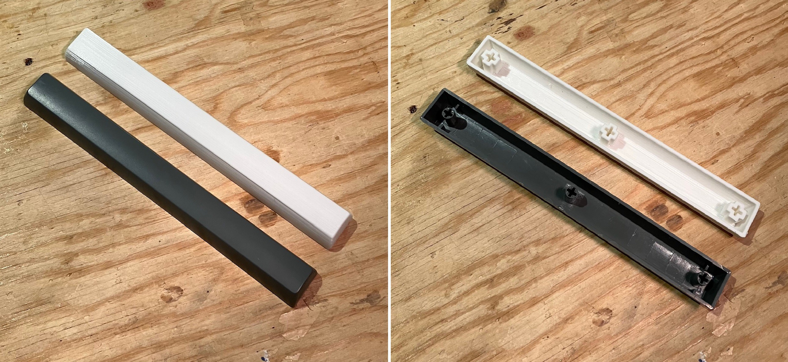
Next step will be to install the electronics.
Klassy Kool Keycaps
The keycaps from KROME Keycaps arrived today. They did a fabulous job. I'm very happy with the result. I don't usually do unboxings but this is how the keycaps were organized in the box.
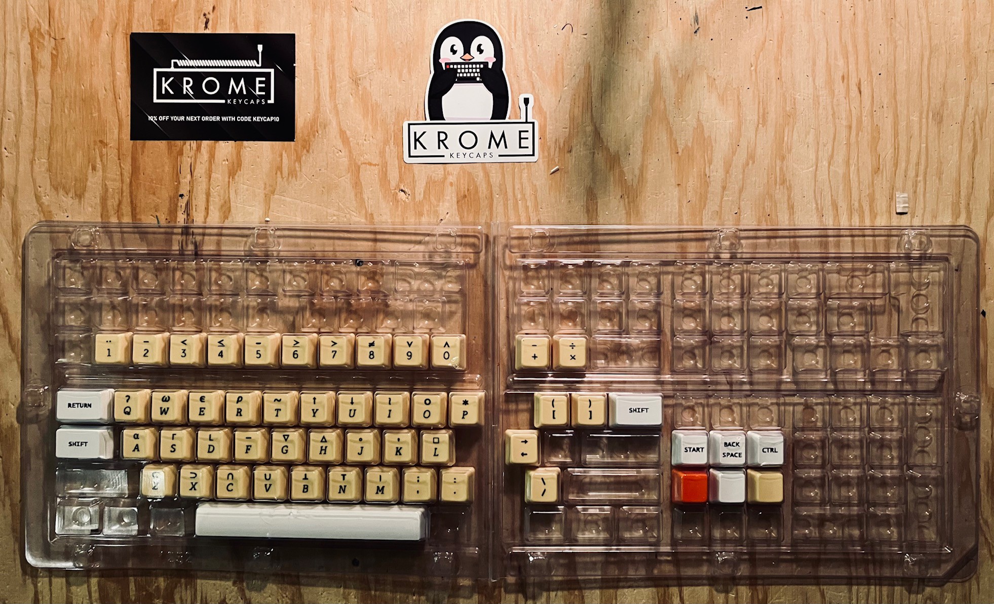
Nice! I didn't waste any time replacing the cheap keycaps with these beauties.
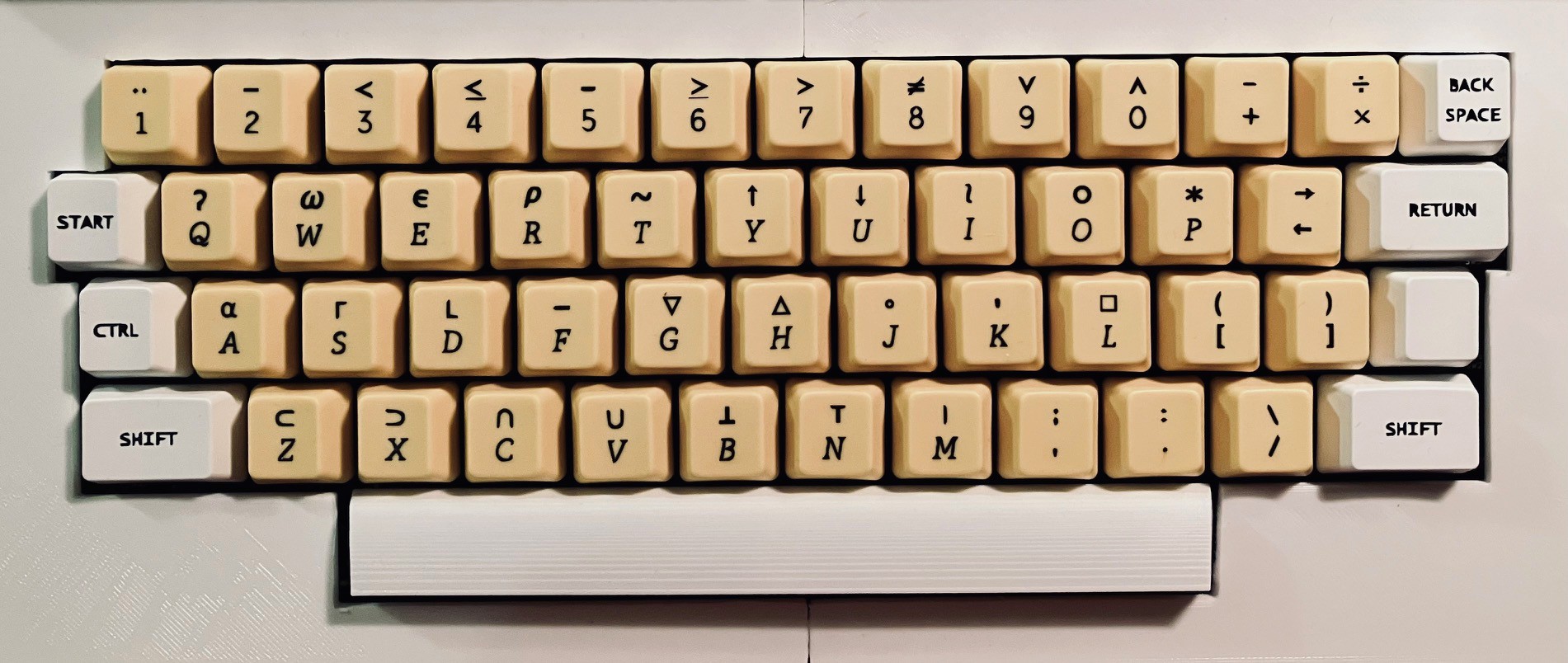
The keycaps are OEM R3 profile. I modeled and reprinted the 8U spacebar based on the 6.25U spacebar that Krome Keycaps sent me. With that I pronounce that the case is complete.
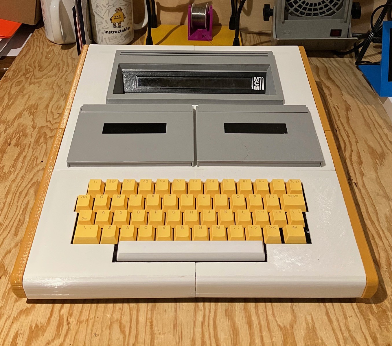
And with that I am updating the main picture for this project to my reproduction, replacing the original photo I was using as a place holder.
A Physical Interface for Virtual Tapes
The wonderful York University Computer Museum MCM/70 Emulator allowed the user to manipulate the cassette drives through the onscreen interface. From the MCM/70 Emulator manual:
The MCM/70 computers were equipped with up to two digital cassette drives. Their purpose was not only to store APL objects but also to offer virtual memory to extend user’s workspace to over 100KB. (In the early 1970s, the virtual memory was available only on some mainframe computers such as the IBM System\370 Models 158 and 168.) Tape mounting. Follow these steps:
Note: The emulator requires that tape names are at most 16-character long. It will not load tapes with longer names.
To eject a tape:
- Left click the selected tape drive to open its lid.
- Access tape menu by right clicking the selected drive.
- Select ”eject”.
- Left click the selected tape drive to close its lid.
To select a tape:
- Left click the selected tape drive to open its lid.
- Right click the selected drive to access tape menu.
- Select one of the tapes from the list (demo.tp, utils.tp, empty.tp).
- Left click the selected tape drive to close its lid.
By ejecting a tape, its content will be saved in the tape’s file located in the tapes directory Tapes of the emulator.
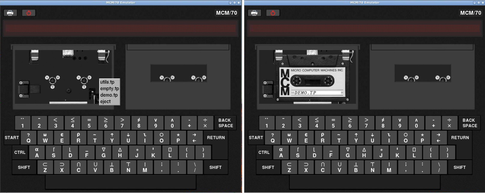
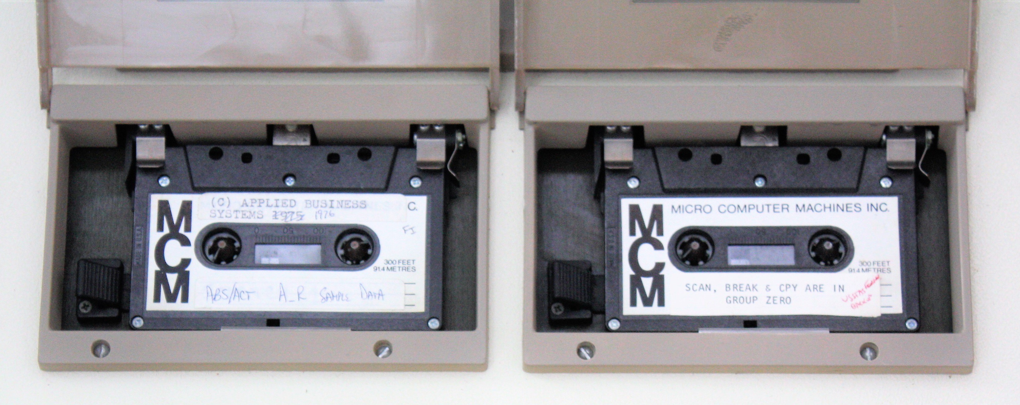
In the first image above I have done a left click to open the lid of the first cassette drive, then right clicked to bring up the tapes menu followed by clicking the demo.tp entry.
I've already stated as part of my Game Plan that I will add the cassette bays to give an authentic look (almost all of the MCM/70 photos online are of the two cassette model) but at least for my first out they will not be functional, instead using the emulator's virtual cassettes. Even though I am using an emulator under the covers, I like for my reproductions to provide as authentic a user experience as possible. So to that end I have added a physical interface for one of the underlying virtual cassettes. I didn't think that doing both cassettes added a lot of value.
Identifying Tapes
I had been playing around lately with the RC522 RFID reader/writer so my first though was to use one to read RFID tags that I would embed into my fake cassette tapes. This would have the advantage of allowing a large number of different tapes, but would add significant complexity to the build. For instance I would have to find and integrate an RFID library into the emulator code. Since the emulator only ships with three different virtual tapes anyway, I decided to go a simpler route and use hall effect sensors to detect magnets that I would embed into the fake cassettes. I already have the pigpio library installed for the keyboard and display so reading the sensors is no problem.
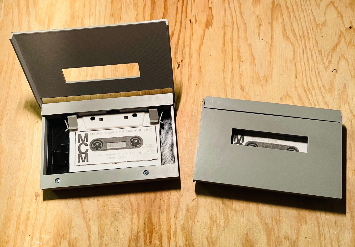
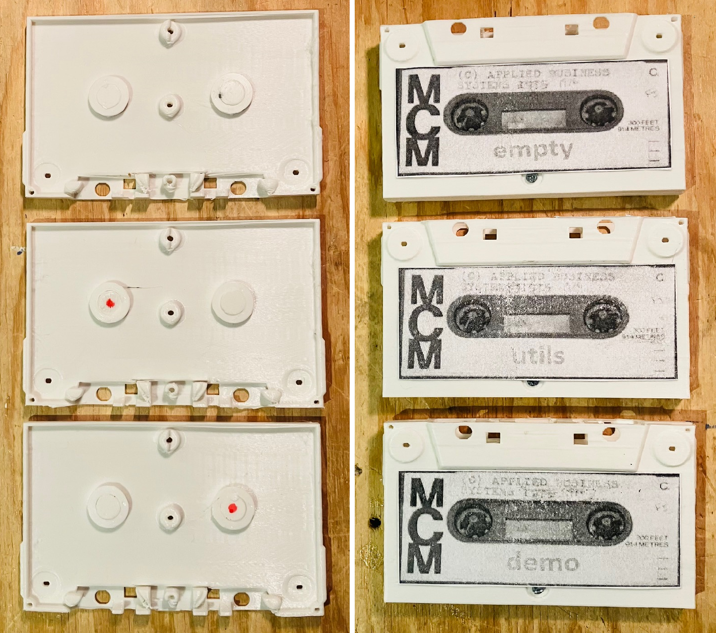
I stared by creating three new "cassettes". I 3D printed some new fake cassette bodies, and created some plugs to hold the magnets (round 6mm in diameter and 3mm height) that could be slotted into the cassette holes.
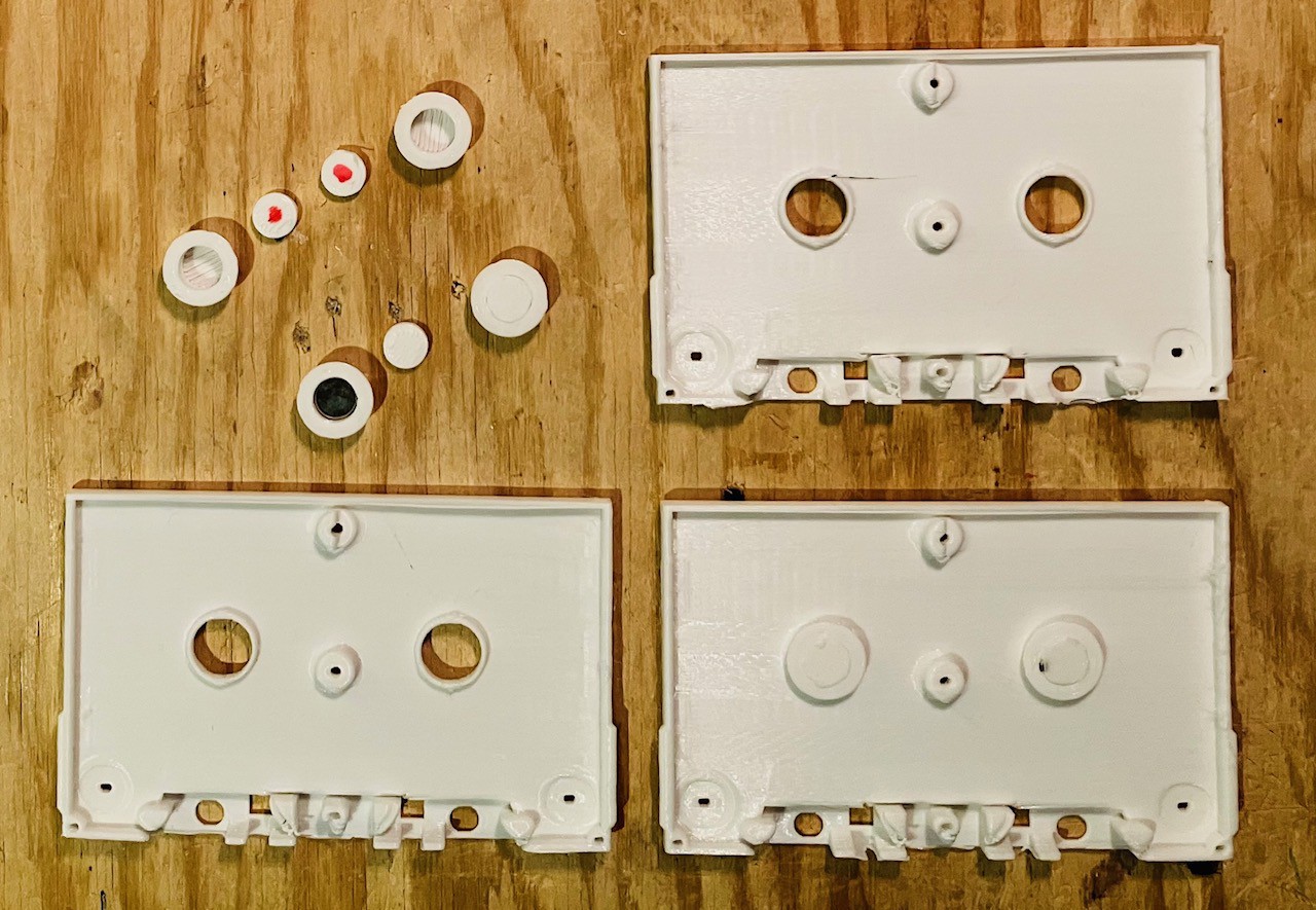
The plugs marked with the red dots do not have a magnet. I put the cassettes together and added some vintage looking labels.
Then I made a "reader" based on two SS451A Omnipolar Hall Effect Switches. These sensors are either on or off depending to the presence or absence of a magnetic field. Omnipolar means that it it doesn't matter what the magnet's polarity is.
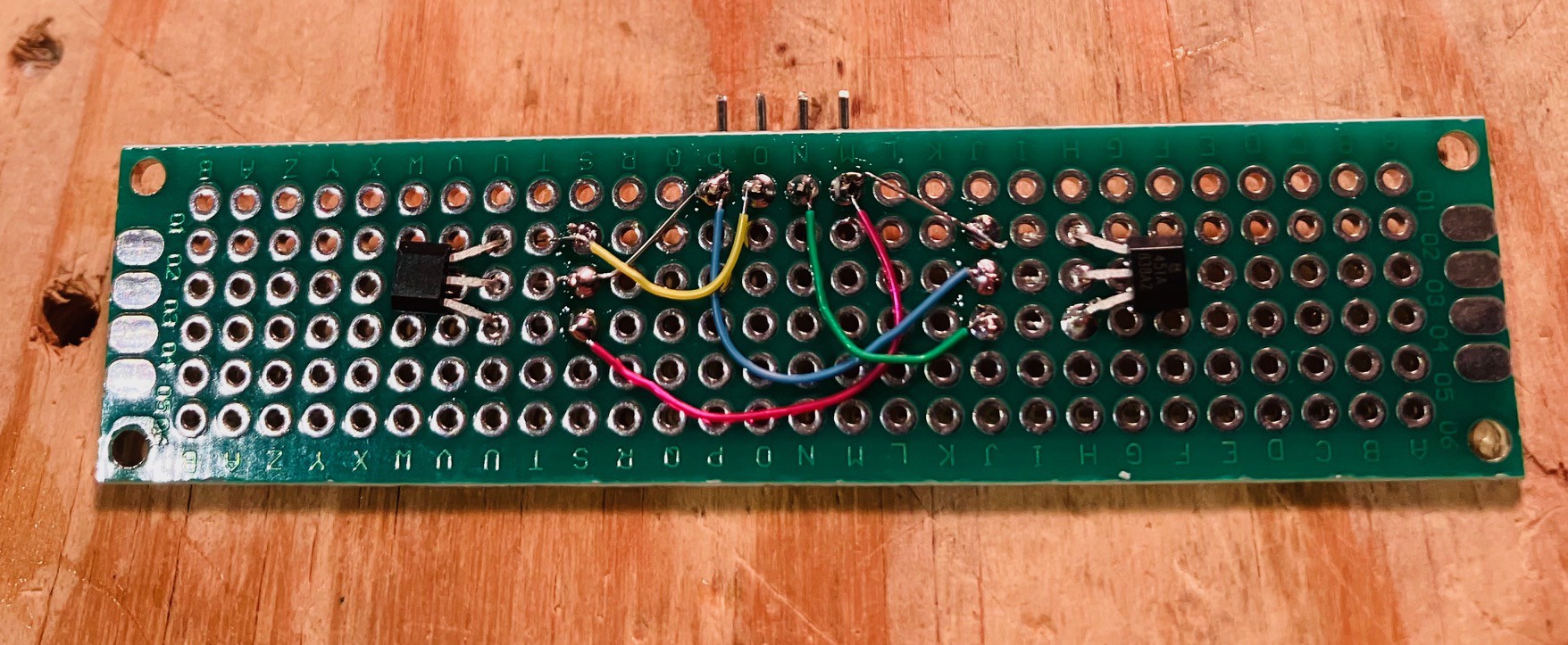
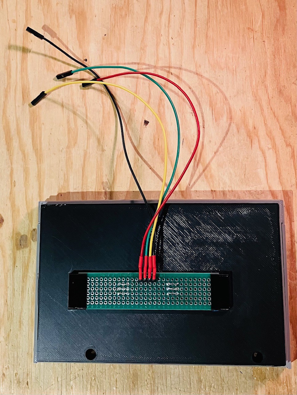
I mounted the reader using some 3D printed standoffs to the back of one of the fake cassette decks so the the sensors would align with the magnets in the cassettes, and added some leads to eventually connect it to the Raspberry Pi.
I connected the wired deck the an Arduino Nano and wrote a small sketch to test the reader. Here is the code.
/*  Test MCM/70 Tape Reading.
*/

int currentState = -1;

// the setup function runs once when you press reset or power the board
void setup() {  // initialize hall effect sensor digital pins.  pinMode(5, INPUT_PULLUP);  pinMode(6, INPUT_PULLUP);
  Serial.begin(115200);  Serial.println("Test start...");

}

// the loop function runs over and over again forever
void loop() {    int fiveState = digitalRead(5);  int sixState = digitalRead(6);
  if (fiveState == 1 && sixState == 1 && currentState != 3) {    if (currentState >= 0) {      Serial.println("Eject");    }    Serial.println("No Tape");    currentState = 3;  } else if (fiveState == 0 && sixState == 0 && currentState != 0) {    Serial.println("Empty Tape");    currentState = 0;  } else if (fiveState == 1 && sixState == 0 && currentState != 2) {    Serial.println("Utils Tape");    currentState = 2;  } else if (fiveState == 0 && sixState == 1 && currentState != 1) {    Serial.println("Demo Tape");    currentState = 1;    }  delay(500);                       // wait a bit
}
Here is a short video of the test.
Looks like it's ready to go. I'll incorporate the cassette into the Emulator code when I start integrating all of the finished pieces into the final build.
Final Assembly
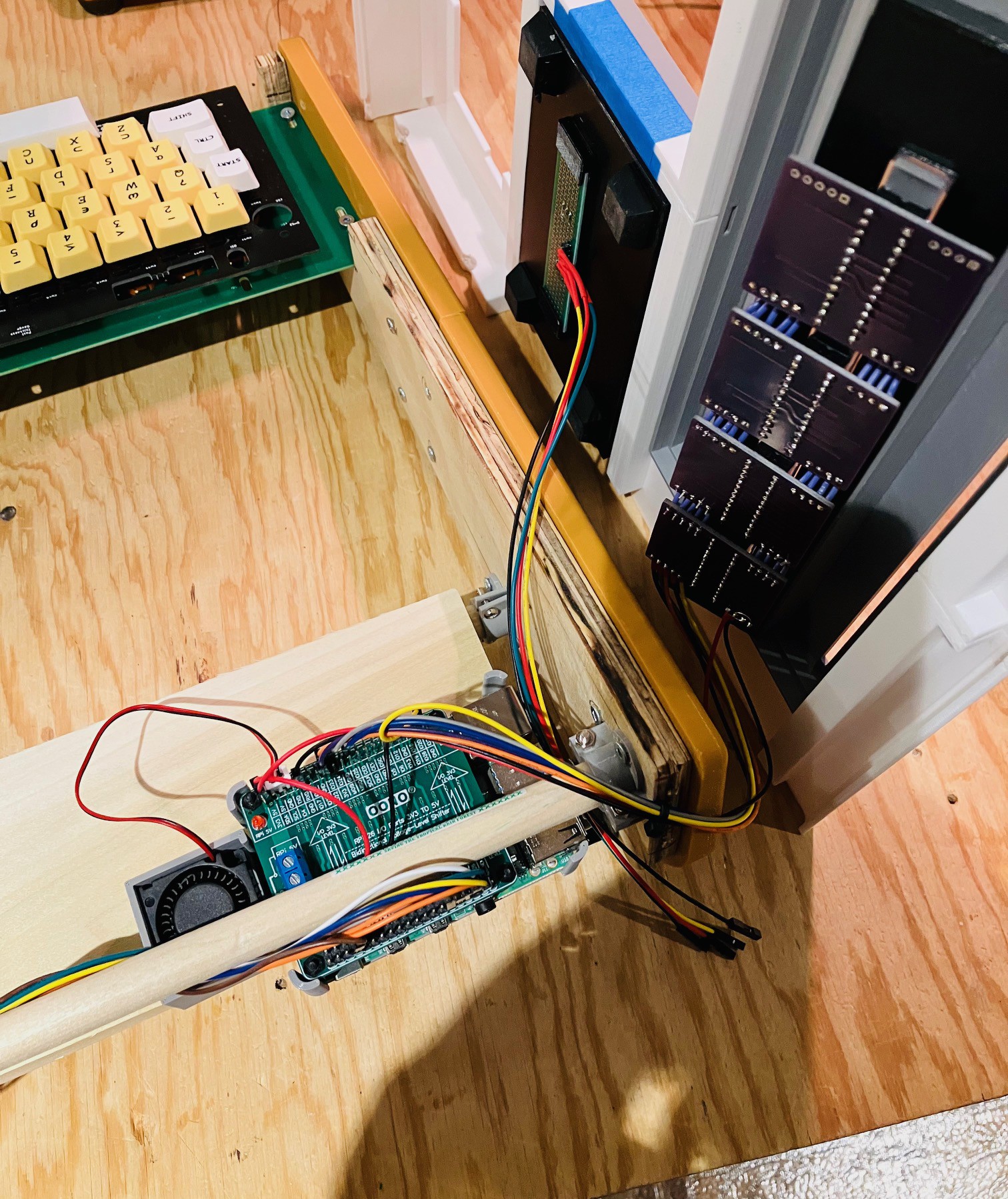
With all the pieces done it was time to put it all together, but first I did one final check of the integrated electronics.
All good. Next:
- Positioned the 3D printed caddy for the Raspberry Pi on the platform as far back as it would go. (until the blue power connector hits the support dowel). Attach it in place with two sided tape and inserted the Raspberry pi.
- Attached the keyboard encoder to the platform at the back of the case with some two sided tape.
- I reinstalled the keyboard.
Then:
- Placing the top cover on it's side I carefully attached the display unit and left hand tape deck. I used a little blue tape along the opening edges for the cassette deck and display to ensure a tight fit.
- I ran the wires from the tape deck out through the back of the case.
- I also installed a little muffin fan (30x30x10 mm) on to the Raspberry Pi caddy and powered it from the 5V side of the Pi hat.
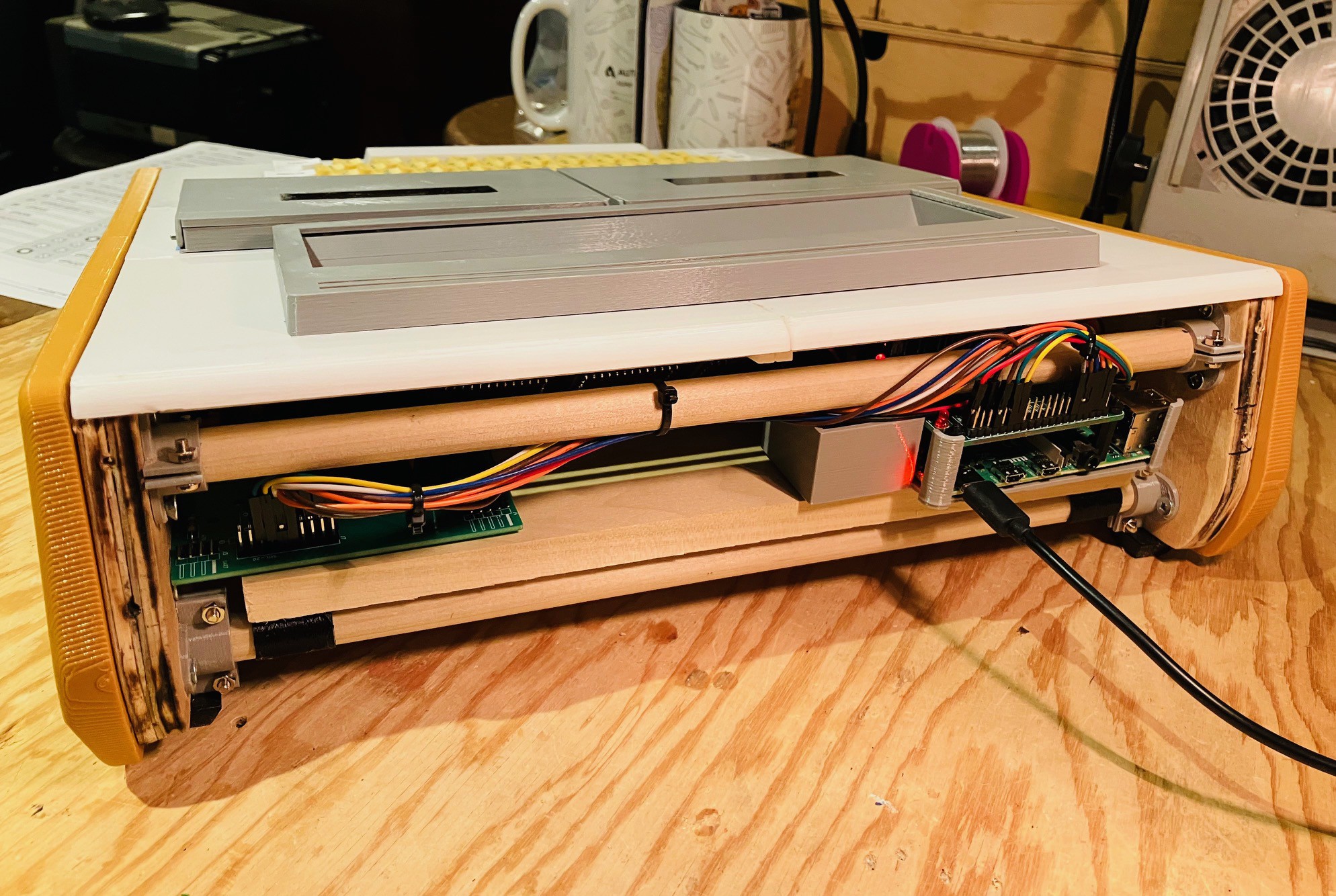
I positioned the Top Panel in place being careful not to the pull or pinch any of the wires.
The tape deck was wired to the following pins:
| Tape Sensor Module | Encoder/Raspberry Pi | Description |
|---|---|---|
| 5V | +5 (from Encoder UART header) | Power |
| GND | GND (from Encoder UART header) | Ground |
| Hall Effect Sensor 1 | GPIO17 | Data Pin |
| Hall Effect Sensor 2 | GPIO27 | Data Pin |
(Note that I was out of power connectors on the Pi HAT so I used the power and GND connectors from the encoder UART header instead.
I did a little cable management as well.
Finally, I reprinted the right hand side of the Back Panel with a cutout for the PI power, HDMI, and A/V Jack and attached it.
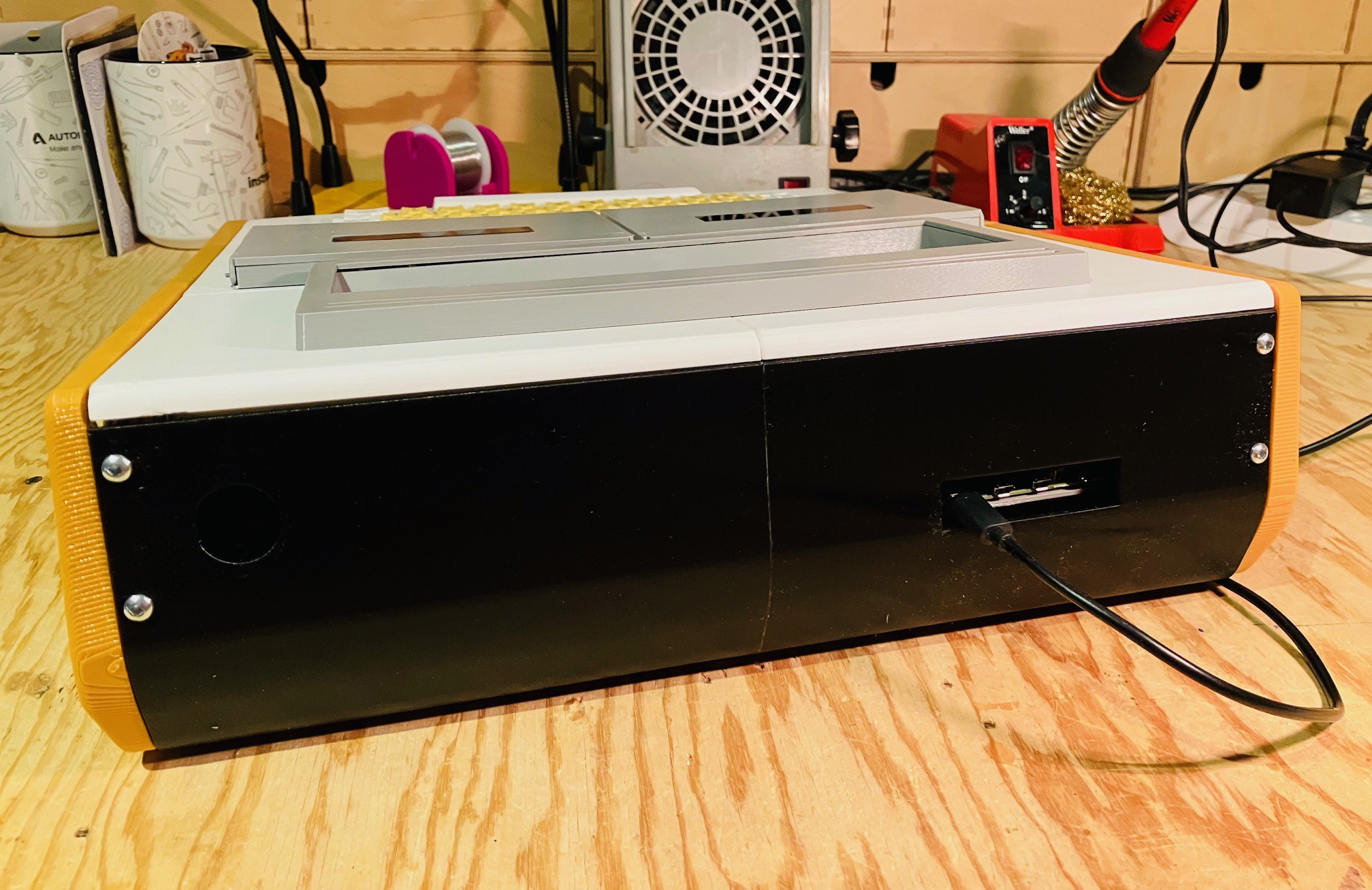
And that's it. The hardware is done!
I still have some software stuff to do like setting up the system to auto boot into the MCM/70 Emulator and integrating the tape deck sensors with the emulator, but this is a pretty big milestone for the project.
Autostart
One of the finishing touches I wanted on this project is to make the Raspberry Pi boot directly into the MCM/70 emulator on startup.
I created an autostart folder on my Pi and switched to that folder. Note that megardi is the logon user name for the Pi and will be different for your system.
mkdir /home/megardi/.config/autostart
cd /home/megardi/.config/autostart
Into the autostart folder just created I added the following two files.
runMCM-70
cd /home/megardi/MCM70E_v2.1_distr
sudo ./mcm
MCM70E_v2.1_distr is the folder when the emulator gets built. For some reason the pigpio library requires root access hence the sudo.
MCM-70.desktop
[Desktop Entry]
Type=Application Name=MCM-70
Exec=/home/megardi/.config/autostart/runMCM-70
In addition the runMCM-70 file must be made executable with the following command:
sudo chmod 777 runMCM-70
Wrapping Up
With autostart done, and the tape sensors integrated into the MCM/70 Emulator, this project is complete. My game plan going forward is to work my way through the MCM/70 Users Guide to test my implementation and learn the APL language.