Close
0%
0%

MCM/70 Reproduction

I am making a full sized MCM/70 reproduction, a Canadian personal computer from 1974.

Similar projects worth following
The MCM/70 computer was conceived, developed, and built in Canada in 1974. It was arguably one of the very first "personal" computers because it was portable, had a built-in keyboard, display, and support for the APL programming language, plus cassette storage. On the other hand, at a cost of $10,000, it was only really accessible to large corporations, the military, governments, and educational institutions.

As soon as I became aware of the MCM/70 I knew that I had to have one, and given the rarity of these machines that means making one. This project will chronicle my MCM/70 Reproduction journey.

Inspiration

I've been a vintage/retro computer enthusiast for a long time now and thought that I had a pretty good handle on all of the machines available in the 60s and 70s. So imagine my surprise when I saw the Kristina Panos February 23, 2022 blog post: INPUTS OF INTEREST: CANADIAN MCM/70 WAS KINDA LIKE THE FIRST CYBERDECK.

Wow. Mind blown. Here was a  beautiful Canadian built personal computer from the mid 70s that I had no idea existed. As I read Kristina's post I became more and more intrigued. The MCM/70 was conceived by professor Mers Kutt of Queen’s University in Kingston, Ontario and was manufactured in Kingston. The company he formed to build the devices, Micro Computer Machines (MCM), was located in Toronto, Ontario. I live in Waterloo, Ontario, so all of this took place in my own back yard so to speak.  Adding to that there was a ‘devastating power struggle’ between Kutt and some of MCM’s investors that in part ultimately lead to the demise of the company. Well I was hooked. Had to know more, had to have one.

Hardware

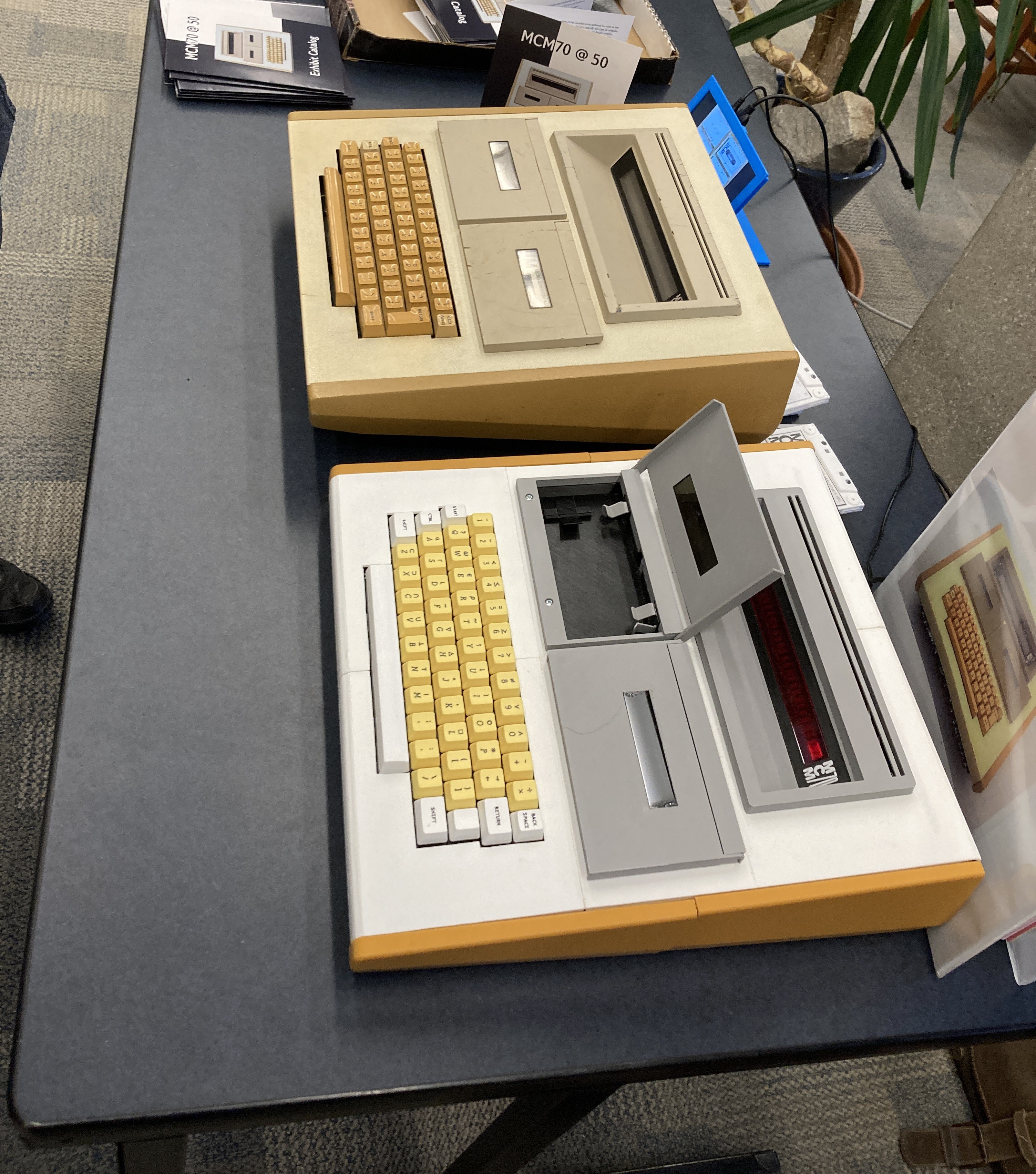
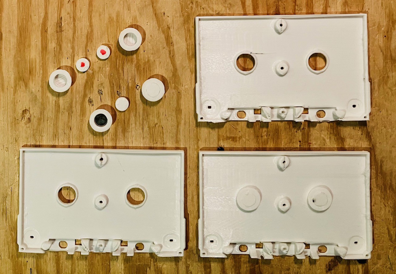
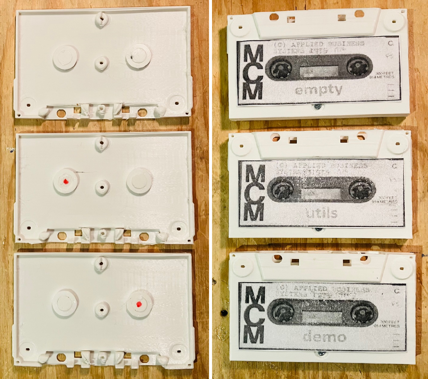
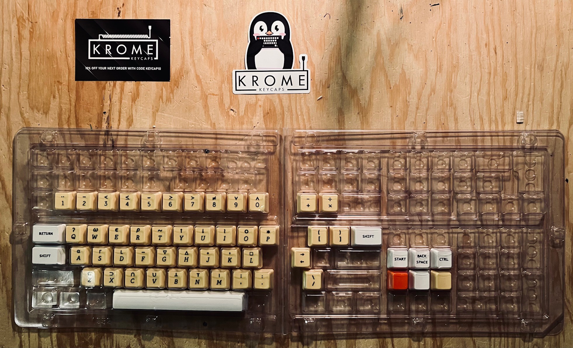
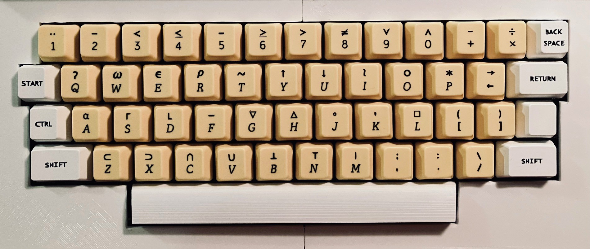
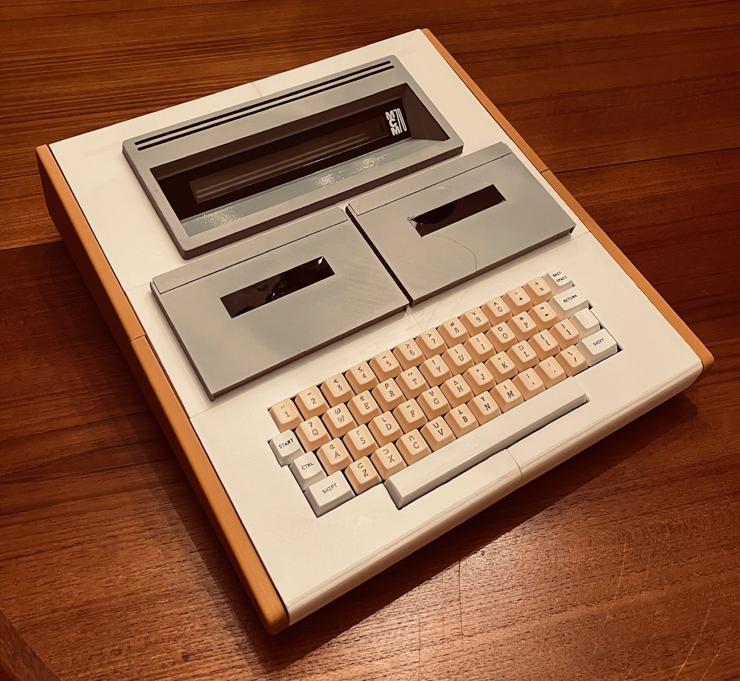
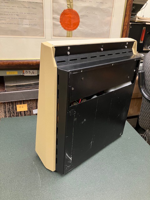
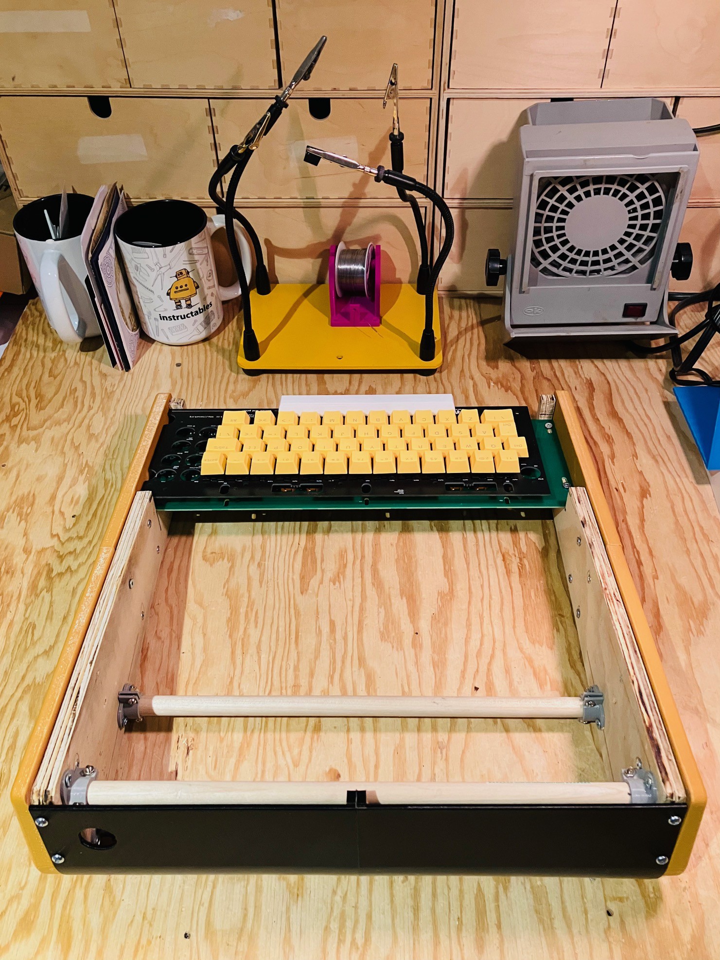
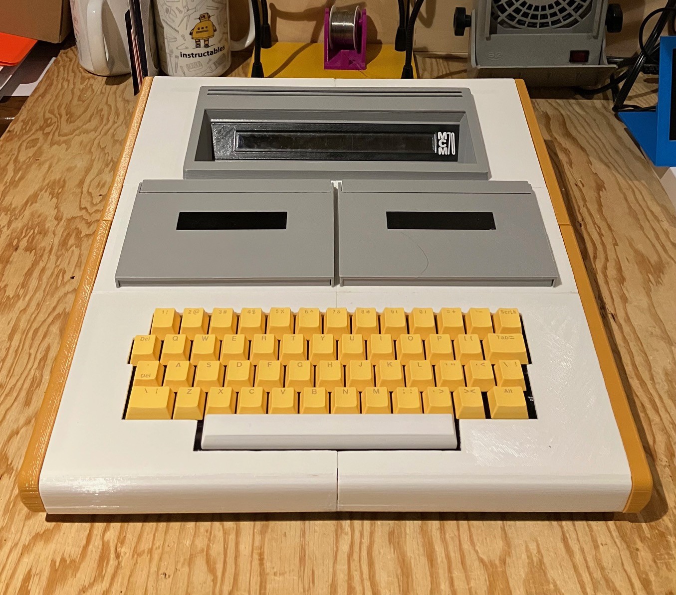
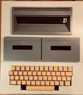
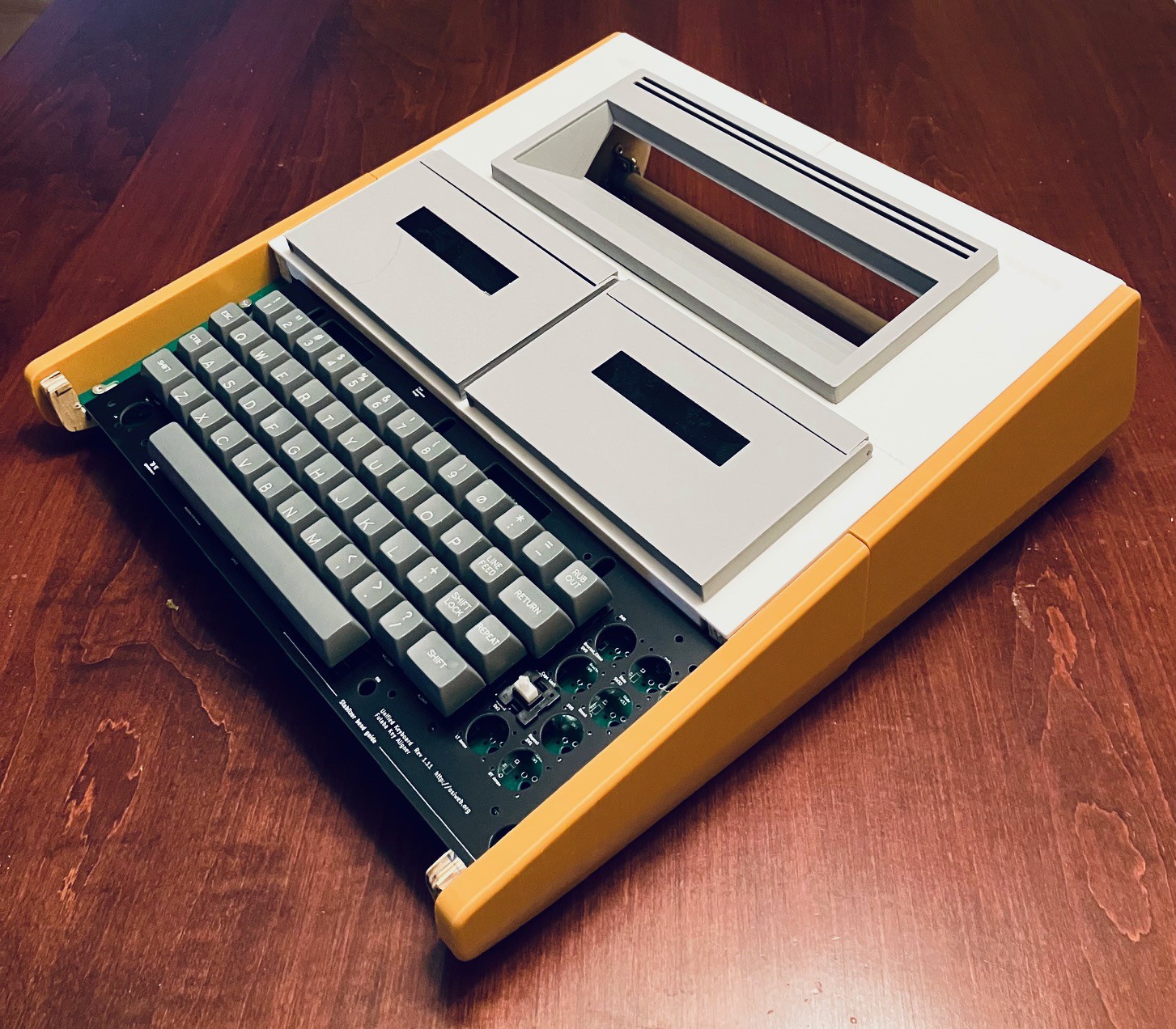
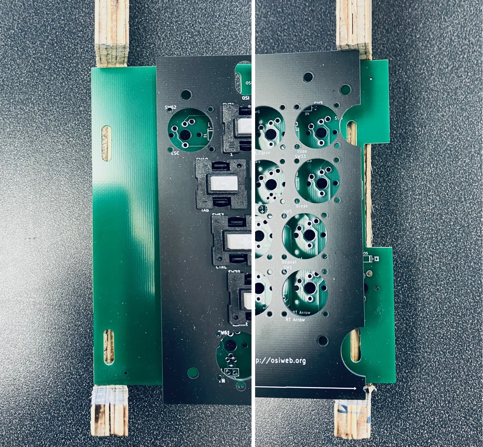
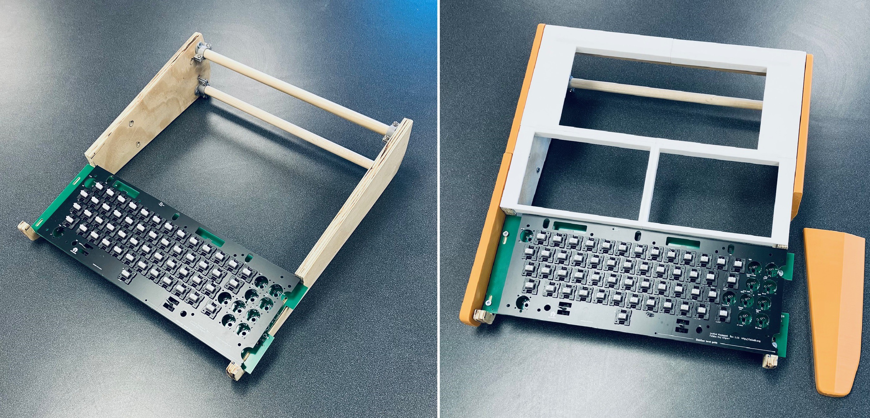
Based on the Intel 8008 microprocessor the MCM/70 had 32KB of ROM and up to 8KB of RAM. For output it used a Burroughs Self-Scan module, a 222 column by 7 row dot matrix display, capable of showing 32 5x7 dot characters at a time.  Because the MCM/70 supported APL out of the box, the keyboard was based on the IBM 2741 layout. Finally up to two cassette decks were used for offline storage and to implement virtual memory.

Software

The MCM/70's operating system consisted of two modules EASY (External Allocation SYstem), and AVS (A Virtual System) which were built into the ROM. These allowed the user to directly interact with the machine. In addition the ROM contained an MCM/APL interpreter. From cassette, APL application libraries could be loaded for finance, mathematics, statistics, education, and games. There was also printer and plotter support software. 

Research

Kristina's blog post was a good place to start learning about the MCM/70.  It's a great summary of the origin of the machine, what it was, and its ultimate fate. I would encourage anyone with an interest in the MCM/70 to start there as I did.

For a more in depth look, the blog post references the book Inventing the PC: the MCM/70 Story by Zbigniew Stachniak. I purchased the book and really enjoyed it. A lot of the book is about the history of the company Micro Computer Machines which I found fascinating. More importantly, towards my goal of making an MCM/70, the book talks a lot about the design of the machine and provides insights into what ultimately led to that design some of which were technical, some practical, and some political.

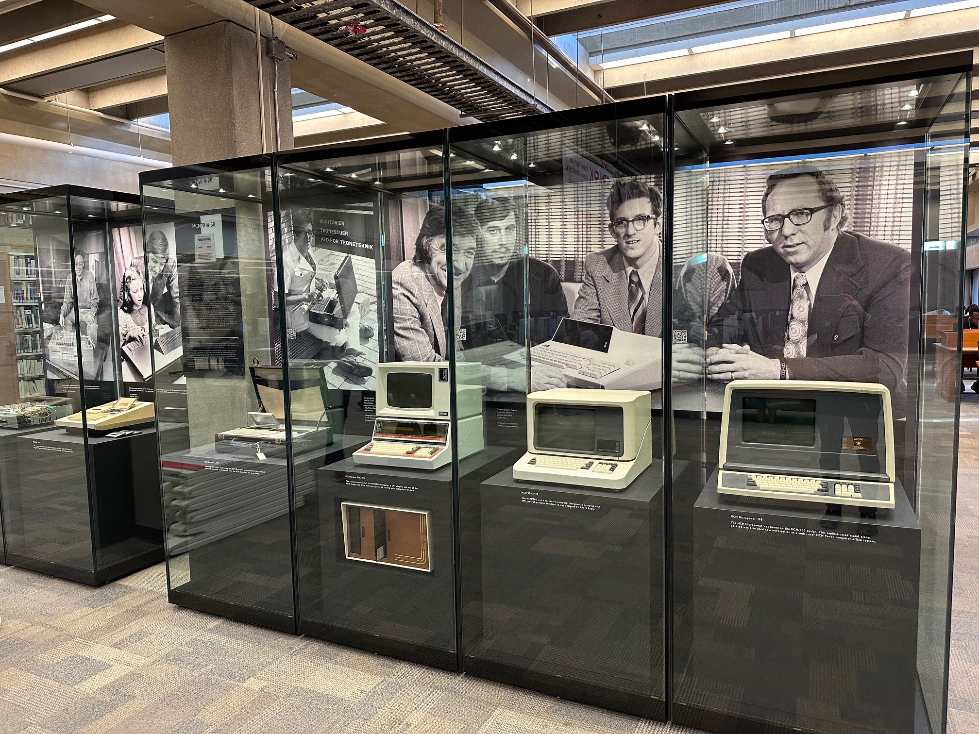
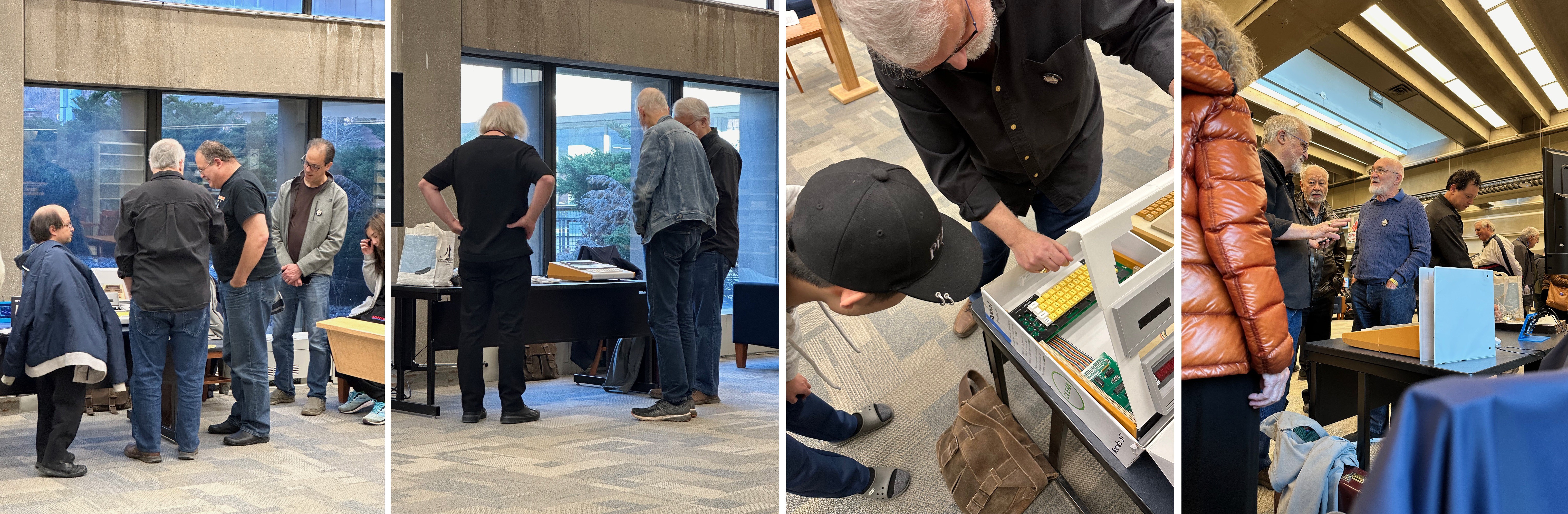
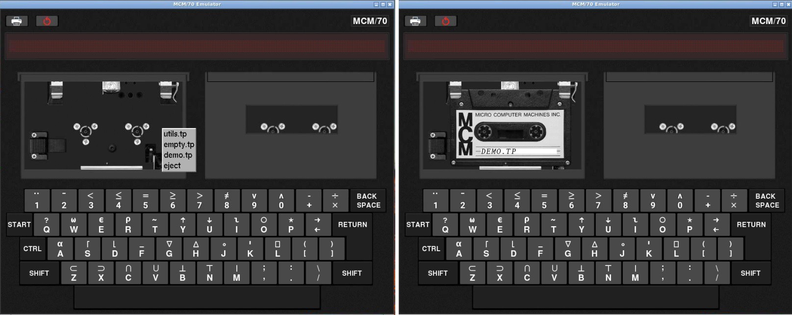
After doing a little more digging I discovered that The York University Computer Museum (YUCoM) has an MCM/70 on display. York University is only about 110 kilometers from where I live, about a hour and a half's drive away. Cool. I also learned that the YUCoM has developed a historically accurate software emulator for the MCM/70 and is offering it free to anyone who requests it. So naturally I requested it through an online contact form and who should answer that request, Zbigniew Stachniak the author of Inventing the PC: the MCM/70 Story who also happens to be the curator of YUCoM.  Small world.  I hope to visit the museum in the near future now that COVID protocols are being relaxed. 

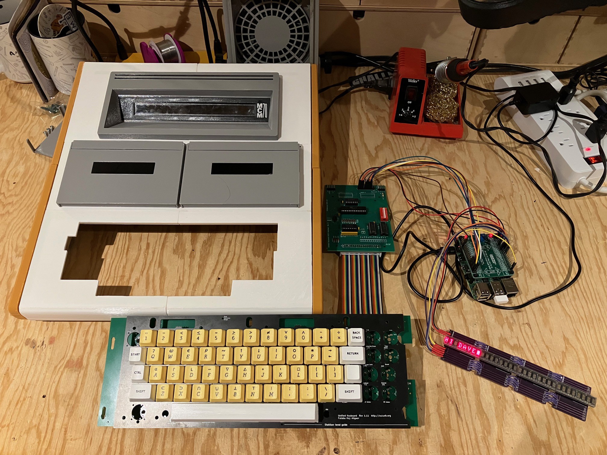
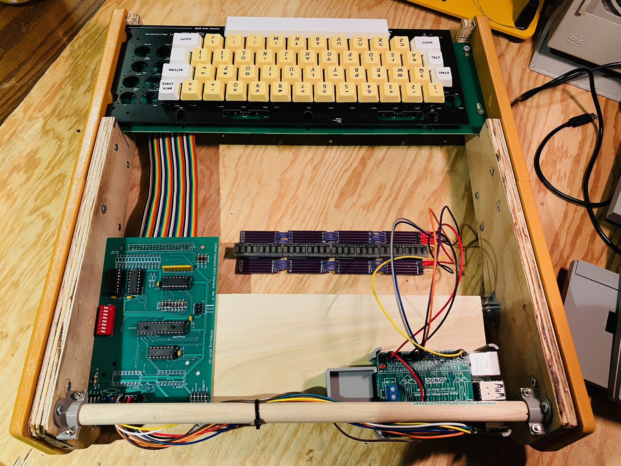
I did some more in depth research into the MCM/70's display and keyboard as these would definitely be the "hard parts" to reproduce. I'll detail my findings in future posts, but I'll say for now that after that research I was convinced that the MCM/70 Reproduction project was feasible, and that I would be happy with the result. So let the fun begin.

The Game Plan

Look. I would like nothing better than to find a dusty old MCM/70 computer for cheap in some thrift shop and restore it to it's former working glory. Realistically we...

Read more »

  • MCM/70 @ 50

    Michael Gardi11/16/2023 at 17:11 3 comments

    On Tuesday November 14th, 2023 I was invited to an event at York University to celebrate "the momentous appearance of the MCM/70 computer - a technological marvel that offered an early glimpse of a new digital reality. "

    MCM/70 @ 50 was organized by Zbigniew (“Ziggy”) Stachniak, curator of the York University Computer Museum and author of the definitive book on the subject "Inventing the PC - The MCM/70 Story" (highly recommended, a great read). The event marked the unveiling of a permanent exhibit in the Steacie Science and Engineering Library at York University, so that current and future York students will know Canada's contribution to the early days of the personal computer. It pays tribute to the makers of the MCM/70 for their hard work towards achieving that goal. The exhibit features a complete line of MCM computers, including an early engineering prototype, an MCM/70, and the only MCM Executive model ever produced. (The MCM Executive is third from the left in the picture below and you can see a picture of Ted Edwards above it demonstrating the MCM Executive during a computer congress in Denmark in August 1973. Many who first saw the Executive thought it was a hoax, a tribute to how advanced it really was.)

              From left to right: Engineering Prototype, MCM/70, MCM Executive, MCM System 800, MCM/900, MCM Micropower.

    The exhibit is extremely well done. It clearly conveys a large amount of information in a relatively small amount of space. With all of the reflecting glass it's hard to get a photo that does justice to how good this exhibit really looks.

    The event was well attended including a number of the principals from MCM that were responsible for creating the MCM/70 . 

    One of those individuals who is pictured above on the far right of the first photo is Cam Farnell. Cam worked as a programmer while the MCM/70 was being developed. He also has an MCM/70 project here on Hackaday Rack8 MCM/70 rack machine replica.

    Above is a photo of Zbigniew Stachniak delivering the opening address.

    As if just being there wasn't enough, I was honored to be asked to bring my MCM/70 reproduction to the event and demonstrate the machine in action. I don't believe that the museum has any working MCM/70s and even if they did they would be too valuable to risk.

    Above is a photo of my reproduction beside a real MCM/70. This was a very cool moment for me.

    There was a fair amount of interest in the reproduction. I was actually pretty busy most of the time (but unfortunately don't have photos to prove it ;-)  

    A couple of interesting notes: 

    • Zbigniew Stachniak can be seen in the second photo from the left. I met "Ziggy's" wife and we had a short discussion on whether he looked more like Albert Einstein or Graham Nash (she thinks Nash).
    • In the third frame from the left, the young man in the baseball cap (unfortunately I did not get his name) works for the government crunching data and producing complex charts and graphs exclusively using APL. He basically gave an APL masterclass using the reproduction to myself and some other onlookers. Quite impressive.
    • In the rightmost frame I am having a discussion with Peter Jennings of Microchess and VisiCalc/VisiCorp fame. It turns out that Peter was/is a huge APL nerd. Around the time he was working on Microchess he wrote a 6502 assembler in APL. I think he had fun exercising his APL skills on the reproduction. 

    For me it was a wonderful afternoon well spent. I met some great people and was honored to play a small part in this great event. Well done Ziggy.

  • Autostart

    Michael Gardi01/30/2023 at 15:46 0 comments

    One of the finishing touches I wanted on this project is to make the Raspberry Pi boot directly into the MCM/70 emulator on startup. 

    I created an autostart folder on my Pi and switched to that folder.  Note that megardi is the logon user name for the Pi and will be different for your system.

    mkdir /home/megardi/.config/autostart
    cd /home/megardi/.config/autostart

    Into the autostart folder just created I added the following two files.

    runMCM-70

    cd /home/megardi/MCM70E_v2.1_distr
    sudo ./mcm

    MCM70E_v2.1_distr is the folder when the emulator gets built. For some reason the pigpio library requires root access hence the sudo.

    MCM-70.desktop

    [Desktop Entry]
    Type=Application Name=MCM-70
    Exec=/home/megardi/.config/autostart/runMCM-70 

    In addition the runMCM-70 file must be made executable with the following command:

    sudo chmod 777 runMCM-70

  • Final Assembly

    Michael Gardi01/21/2023 at 02:54 0 comments

    With all the pieces done it was time to put it all together, but first I did one final check of the integrated electronics.

    All good. Next:

    • I reinstalled the keyboard.
    • Attached the keyboard encoder to the platform at the back of the case with some two sided tape.
    • Positioned the 3D printed caddy for the Raspberry Pi on the platform as far back as it would go. (until the blue power connector hits the support dowel). Attach it in place with two sided tape and inserted the Raspberry pi. 

    Then:

    • Placing the top cover on it's side I carefully attached the display unit and left hand tape deck. I used a little blue tape along the opening edges for the cassette deck and display to ensure a tight fit.
    • I ran the wires from the tape deck out through the back of the case.
    • I also installed a little muffin fan (30x30x10 mm) on to the Raspberry Pi caddy and powered it from the 5V side of the Pi hat.

    I positioned the Top Panel in place being careful not to the pull or pinch any of the wires.

    The tape deck was wired to the following pins:

    Tape Sensor ModuleRaspberry PiDescription
    5V5VPower
    GNDGNDGround
    Hall Effect Sensor 1GPIO17Data Pin
    Hall Effect Sensor 2GPIO27Data Pin

    I did a little cable management as well.

    Finally, I reprinted the right hand side of the Back Panel with a cutout for the PI power, HDMI, and A/V Jack and attached it.

    And  that's it. The hardware is done!

    I still have some software stuff to do like setting up the system to auto boot into the MCM/70 Emulator and integrating the tape deck sensors with the emulator, but this is a pretty big milestone for the project.

  • A Physical Interface for Virtual Tapes

    Michael Gardi01/18/2023 at 08:18 0 comments

    The wonderful York University Computer Museum MCM/70 Emulator allowed the user to manipulate the cassette drives through the onscreen interface. From the MCM/70 Emulator manual:

    The MCM/70 computers were equipped with up to two digital cassette drives. Their purpose was not only to store APL objects but also to offer virtual memory to extend user’s workspace to over 100KB. (In the early 1970s, the virtual memory was available only on some mainframe computers such as the IBM System\370 Models 158 and 168.)

    Tape mounting. Follow these steps:

    1. Start MCM/70E.
    2. Left click the selected tape drive to open its lid.
    3. Right click the selected drive to access tape menu.
    4. Select a tape.
    5. Left click the selected tape drive to close its lid.

    Note: The emulator requires that tape names are at most 16-character long. It will not load tapes with longer names.

    Ejecting a tape. To eject a tape:

    1. Left click the selected tape drive to open its lid.
    2. Access tape menu by right clicking the selected drive.
    3. Select ”eject”.
    4. Left click the selected tape drive to close its lid.

    By ejecting a tape, its content will be saved in the tape’s file located in the tapes directory Tapes of the emulator. 

    In the first image above I have done a left click to open the lid of the first cassette drive and then right clicked to bring up the tapes menu. Notice that in addition to eject there are three tapes that ship with the emulator: utils.tp, empty.tp, and demo.tp. In the second image I have selected the demo tape.

    I've already stated as part of my Game Plan that I will add the cassette bays to give an authentic look (almost all of the MCM/70 photos online are of the two cassette model) but at least for my first out they will not be functional, instead using the emulator's virtual cassettes. Even though I am using an emulator under the covers, I like for my reproductions to provide as authentic a user experience as possible. So to that end I have added a physical interface for one of the underlying virtual cassettes. I didn't think that doing both cassettes added a lot of value.

    Identifying Tapes

    I had been playing around lately with the RC522 RFID reader/writer so my first though was to use one to read RFID tags that I would embed into my fake cassette tapes. This would have the advantage of allowing a large number of different tapes, but would add significant complexity to the build. For instance I would have to find and integrate an RFID library into the emulator code. Since the emulator only ships with three different virtual tapes anyway, I decided to go a simpler route and use hall effect sensors to detect magnets that I would embed into the fake cassettes. I already have the pigpio library installed for the keyboard and display so reading the sensors is no problem.

    I stared by creating three new "cassettes".  I 3D printed some new fake cassette bodies, and created some plugs to hold the magnets (round 6mm in diameter and 3mm height) that could be slotted into the cassette holes.

    The plugs marked with the red dots do not have a magnet.  I put the cassettes together and added some vintage looking labels.

    Then I made a "reader" based on two SS451A Omnipolar Hall Effect Switches. These sensors are either on or off depending to the presence or absence of a magnetic field. Omnipolar means that it it doesn't matter what the magnet's polarity is. 

    I mounted the reader using some 3D printed standoffs to the back of one of the fake cassette decks so the the sensors would align with the magnets in the cassettes, and added some leads to eventually connect it to the Raspberry Pi.

    I connected the wired deck the an Arduino Nano and wrote a small sketch to test the reader.  Here is the code.

    /*
      Test MCM/70 Tape Reading.
    */
    
    int currentState = -1;
    
    // the setup function runs once when you press reset or power the board
    void setup() {
      // initialize hall effect sensor digital pins.
     pinMode(5, INPUT_PULLUP);
    ...
    Read more »

  • Klassy Kool Keycaps

    Michael Gardi01/01/2023 at 03:03 0 comments

    The keycaps from KROME Keycaps arrived today. They did a fabulous job. I'm very happy with the result. I don't usually do unboxings but this is how the keycaps were organized in the box.

    Nice! I didn't waste any time replacing the cheap keycaps with these beauties.

    The keycaps are OEM R3 profile. I modeled and reprinted the 8U spacebar based on the 6.25U spacebar that Krome Keycaps sent me. With that I pronounce that the case is complete.

    And with that I am updating the main picture for this project to my reproduction, replacing the original photo I was using as a place holder.

  • Finishing the Case

    Michael Gardi12/29/2022 at 02:51 0 comments

    So  with the major components of the project completed and tested it's time to start putting it all together. The first thing I did was to put the dowel and flanges that I removed from the front of the case (to make room for the keyboard) to the rear of the case level with the existing bottom dowel.

    I cut a piece of 1/2 x 4 inch pine to size and attached some printed brackets in order to mount the board to the dowels.

    This will give me a platform to mount the Raspberry Pi 4 and the keyboard encoder.

    You might have noticed that I also modeled a back panel for the case. 

    The original back panel had a fuse, a printer connector, lots of screws, and other details.

    I decided for my reproduction to keep things simple and did not follow suit.  One reason is that the original MCM/70 sat on a black box that extended down below the sides. At this point I don't think I'm going to do that. On most of the pictures you see of the MCM/70, the black box bottom is never really shown. In fact I didn't even know it existed until I visited the York University Computer Museum and saw an original (pictured below). 

    I  might revisit this down the road but I have to admit I like the nice clean look of my reproduction without the bulky bottom.

    I attached the keyboard panel to the top panel with a good CA glue and added a brace to the front part of the panel.

    Putting it all together with the tape drives and display this is what you end up with.

    Almost there! The keycaps pictured above are still the cheap ones from Amazon. I have ordered custom keycaps from KROME Keycaps. They have been great to work with and the order is in transit from Great Briton. I'm very excited to see the result. 

    Also note that I have not been able to track down an 8U or 9U spacebar in yellow or even white. So I modeled and 3D printed the one you see above. I'm pretty happy with the result. Here is what it looks like compared to the 8U spacebar from the OSI keyset.

    Next step will be to install the electronics. 

  • Wiring

    Michael Gardi12/02/2022 at 15:13 0 comments

    As with my Sol-20 project, the keyboard encoder is expecting 5V while the Raspberry Pi 4 operates at 3.3V.  So to overcome this I purchase a Voltage-Level Shifter Module from Amazon. Here is what it looks like.

    I am using the Sol-20 header on the encoder and the pinout looks like this.

    So here is how I wired the keyboard. Note that for the exception of +5V and GND lines which are wired to the 3.3V side or the level shifter, all of the other connections are wired to the 5V side.

    Keyboard EncoderRaspberry PiDescription
    +5V5VPower
    GNDGNDGround
    D0GPIO5Key 0 bit (low)
    D1GPIO6Key 1 bit
    D2GPIO12Key 2 bit
    D3GPIO13Key 3 bit
    D4GPIO19Key 4 bit
    D5GPIO16Key 5 bit
    D6GPIO26Key 6 bit
    D7GPIO20Key 7 bit (high)
    STROBEGPIO4Key ready on falling edge.


    The display has the following pinouts.

    All of the following connections are wired to the 3.3V of the level shifter.

    Display ModuleRaspberry PiDescription
    3.3V3.3VPower
    GNDGNDGround
    dataGPIO21Data Pin
    selectGPIO22Register Select  Pin
    clockGPIO23Clock Pin
    enableGPIO24Chip Enable Pin
    resetGPIO25Reset Pin


    Next step, mount everything into the case.

  • Keyboard and Display Integration Test

    Michael Gardi12/01/2022 at 16:57 0 comments

    With the keyboard and encoder assembled it was time to test. First I had to make changes to the York University MCM/70 emulator. I took the opportunity to switch away from the Wiring Pi library to access the Raspberry Pi's GPIO pins. Wiring Pi has been deprecated so I am now using the pigpio library for both the display and keyboard GPIO access.  Pigpio is installed by default on Raspberry Pi OS. 

    The library is referenced in the code through the pigpio header file.

    #include <pigpio.h>

     Also when building the code the pigpio library now needs to be referenced.

    gcc mcm.c -lGL -lglut -lpigpio -o mcm

    It was an easy change since the API calls are very similar.

    Here is a short video of the display and keyboard in action. A couple of notes.

    • The emulator is now running on a Raspberry Pi 4. Much faster than the model 2 I was using. In fact the timing test from the MCM/70 Emulator manual ( 0.7 ÷ ι255 ) runs in about 18 seconds. On the original hardware this test runs in 50 seconds. There is a setting so the emulator can be slowed down to match historical speeds.  Check out the video.
    • The keycaps I am using are not the final ones. This was a cheap set I got from Amazon because the color was a pretty good match. I am in touch with a couple of companies that make custom keycaps to hopefully get more accurate reproduction keycaps.
    • When the MCM/70 is "calculating" you will see random dots on the display. This is because the machine was severely memory constrained so display memory was used when the display itself was not required.

    I have printed the case cover for the keyboard area. Again these are not the final keycaps so the spacebar in particular shown here is 6U while the original's was 9U. 

    Needs a bit of "fit and finish" but getting close.

  • More Keyboard Stuff

    Michael Gardi11/12/2022 at 22:48 2 comments

    So I printed a new side panel with a slot to accommodate the protruding keyboard PCB.

    I was able to reattach the side panel and mount the keyboard. For the moment I have attached the keyboard from my Challenger 1P project as it already has the keycaps installed and the layout is almost exactly the same as for the MCM/70. 

    I can now start to model the final keyboard piece of the case skin.

  • Installing the Keyboard

    Michael Gardi11/10/2022 at 21:59 0 comments

    Today I integrated the keyboard into the frame I have constructed. The first thing I did was to remove the front most dowel and cut a notch in the side panels to accommodate the  keyboard.

    Now I'd like to brag that I was thinking ahead about how the keyboard would be attached when I built the frame, but the truth of the matter is that I got very lucky that the width of the original MCM/70 happens to work out perfectly with respect to the mounting holes in Dave's keyboard.

    The only issue here is that the keyboard PCB sticks out a bit past the right inner side panel. So I screwed down the keyboard, re-attached outside side panels, and set the top case panel in place.

    Of course the right outside side panel will not go on because of the keyboard sticking out. I'll correct this by reprinting that part with a slot to accommodate the protruding keyboard PCB. 

View all 26 project logs

Enjoy this project?

Share

Discussions

svofski wrote 11/15/2023 at 14:14 point

Virtual memory on a compact cassette, that's curious. Are they regular compact cassettes or D/CAS type tapes?

  Are you sure? yes | no

Michael Gardi wrote 11/15/2023 at 16:34 point

The tape drives were MFE250s. Here is a video of one in action: https://www.youtube.com/watch?v=McPicP2BQfY

  Are you sure? yes | no

svofski wrote 11/15/2023 at 18:11 point

Amazing. I'm developing Tapeshnik, a computer tape drive based on a commercially available mechanism. I'm also trying to build a fully custom tape transport with direct drive hubs. But it's all early work in progress yet. I guess I could make a hackaday.io project for it.

  Are you sure? yes | no

Daniel Ross wrote 03/06/2023 at 19:34 point

WOW that is some workmanship, great detail,, something about that "old" tech that's ...soothing.

Nicely done

  Are you sure? yes | no

Michael Gardi wrote 03/07/2023 at 12:35 point

Thank you so much for the kind words Daniel.

  Are you sure? yes | no

Michael Kwun wrote 01/30/2023 at 18:59 point

this is brilliant. from the logs, this looks like it will only be a one-off, but if by some chance I'm wrong and there might be an option to acquire one of these, I'd love to hear about it

  Are you sure? yes | no

Michael Gardi wrote 02/02/2023 at 18:02 point

I'll be writing up an Instructable detailing the steps necessary to make an MCM/70, however there are no plans to make or sell these. Sorry. 

  Are you sure? yes | no

Mark Matlock wrote 12/21/2022 at 23:13 point

I actually used a MCM/70 with 8K Ram and dual cassettes in 1978 at Firestone research in Akron. Since it was portable, you could check it out from the lab and use it at home. I learned APL by using it and became a fan of APL. At the lab we also had IBM 5100 APL desktops and APL available via timeshare terminals on the IBM 360. Later at ADM research I used APL-11 on a PDP-11/44. Today I have APL-11 on my PiDP-11/70.

  Are you sure? yes | no

Michael Gardi wrote 12/22/2022 at 00:09 point

I’m not sure I have heard from anyone else that has actually used an MCM/70. Very cool.  I played around with APL a bit in the early 80s over a time share network. I’m hoping to re familiarize myself with APL when I get everything put together. 

  Are you sure? yes | no

Mark Matlock wrote 12/22/2022 at 04:08 point

The memory management of the MCM/70 was really amazing. Usually one of the cassettes was working as temporary storage of variables and functions that were not needed for the execution if the immediate operations. It was amazing what you could do with so little RAM. The one line display was a bit limiting but APL can accomplish a lot with a single line of code. I once wrote Conway's Game of Life in one (long) line of APL. A single matrix variable held the starting cells.

  Are you sure? yes | no

Peabody1929 wrote 05/11/2022 at 17:27 point

The Computer History Museum in Mountain View, CA has two MCM/70s in it collection.  There are numerous documents and manuals for it.  If you search the collection for the MCM/70, one of the objects has photos of the boards inside the machine.  

  Are you sure? yes | no

Ken Yap wrote 04/03/2022 at 00:10 point

👍 This is cool. I like projects that involve unearthing some fascinating technical history. Should be interesting.

  Are you sure? yes | no

Michael Gardi wrote 04/03/2022 at 03:27 point

Thanks Ken. I’ve already learned so much about this historic machine.

  Are you sure? yes | no

Cees Meijer wrote 04/02/2022 at 19:45 point

OMG! You're doing it Again!  Do you have unlimited time on your hands for all these projects ?

  Are you sure? yes | no

Michael Gardi wrote 04/02/2022 at 20:56 point

Actually I’m retired Cees, so I kind of do have the time.

  Are you sure? yes | no

Tom Nardi wrote 03/31/2022 at 02:32 point

If there's anyone who can do this project justice, it's you. Very excited to see your take on this unique machine.

  Are you sure? yes | no

Michael Gardi wrote 03/31/2022 at 15:17 point

Thanks Tom.  As a proud Canadian I'm excited too!

  Are you sure? yes | no

Similar Projects

Does this project spark your interest?

Become a member to follow this project and never miss any updates