 Michael Gardi
The wonderful York University Computer Museum MCM/70 Emulator allowed the user to manipulate the cassette drives through the onscreen interface. From the MCM/70 Emulator manual:
The MCM/70 computers were equipped with up to two digital cassette drives. Their purpose was not only to store APL objects but also to offer virtual memory to extend user’s workspace to over 100KB. (In the early 1970s, the virtual memory was available only on some mainframe computers such as the IBM System\370 Models 158 and 168.)
Tape mounting. Follow these steps:
- Start MCM/70E.
- Left click the selected tape drive to open its lid.
- Right click the selected drive to access tape menu.
- Select a tape.
- Left click the selected tape drive to close its lid.
Note: The emulator requires that tape names are at most 16-character long. It will not load tapes with longer names.
Ejecting a tape. To eject a tape:
- Left click the selected tape drive to open its lid.
- Access tape menu by right clicking the selected drive.
- Select ”eject”.
- Left click the selected tape drive to close its lid.
By ejecting a tape, its content will be saved in the tape’s file located in the tapes directory Tapes of the emulator.
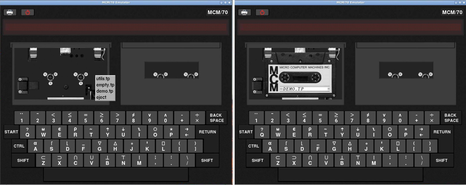
In the first image above I have done a left click to open the lid of the first cassette drive and then right clicked to bring up the tapes menu. Notice that in addition to eject there are three tapes that ship with the emulator: utils.tp, empty.tp, and demo.tp. In the second image I have selected the demo tape.
I've already stated as part of my Game Plan that I will add the cassette bays to give an authentic look (almost all of the MCM/70 photos online are of the two cassette model) but at least for my first out they will not be functional, instead using the emulator's virtual cassettes. Even though I am using an emulator under the covers, I like for my reproductions to provide as authentic a user experience as possible. So to that end I have added a physical interface for one of the underlying virtual cassettes. I didn't think that doing both cassettes added a lot of value.
Identifying Tapes
I had been playing around lately with the RC522 RFID reader/writer so my first though was to use one to read RFID tags that I would embed into my fake cassette tapes. This would have the advantage of allowing a large number of different tapes, but would add significant complexity to the build. For instance I would have to find and integrate an RFID library into the emulator code. Since the emulator only ships with three different virtual tapes anyway, I decided to go a simpler route and use hall effect sensors to detect magnets that I would embed into the fake cassettes. I already have the pigpio library installed for the keyboard and display so reading the sensors is no problem.
I stared by creating three new "cassettes". I 3D printed some new fake cassette bodies, and created some plugs to hold the magnets (round 6mm in diameter and 3mm height) that could be slotted into the cassette holes.
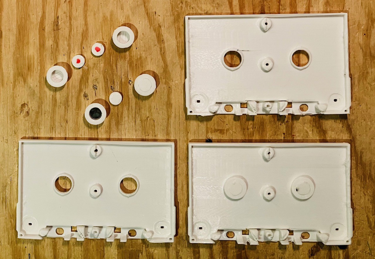
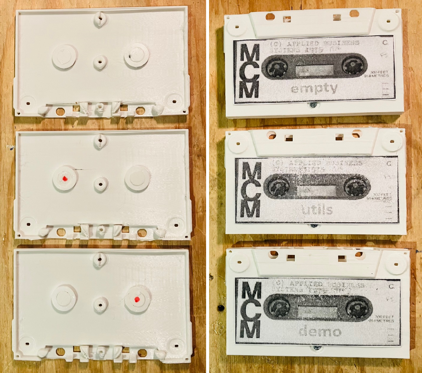
The plugs marked with the red dots do not have a magnet. I put the cassettes together and added some vintage looking labels.
Then I made a "reader" based on two SS451A Omnipolar Hall Effect Switches. These sensors are either on or off depending to the presence or absence of a magnetic field. Omnipolar means that it it doesn't matter what the magnet's polarity is.
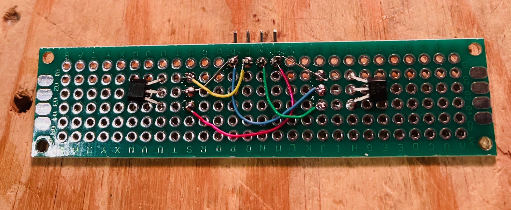
I mounted the reader using some 3D printed standoffs to the back of one of the fake cassette decks so the the sensors would align with the magnets in the cassettes, and added some leads to eventually connect it to the Raspberry Pi.
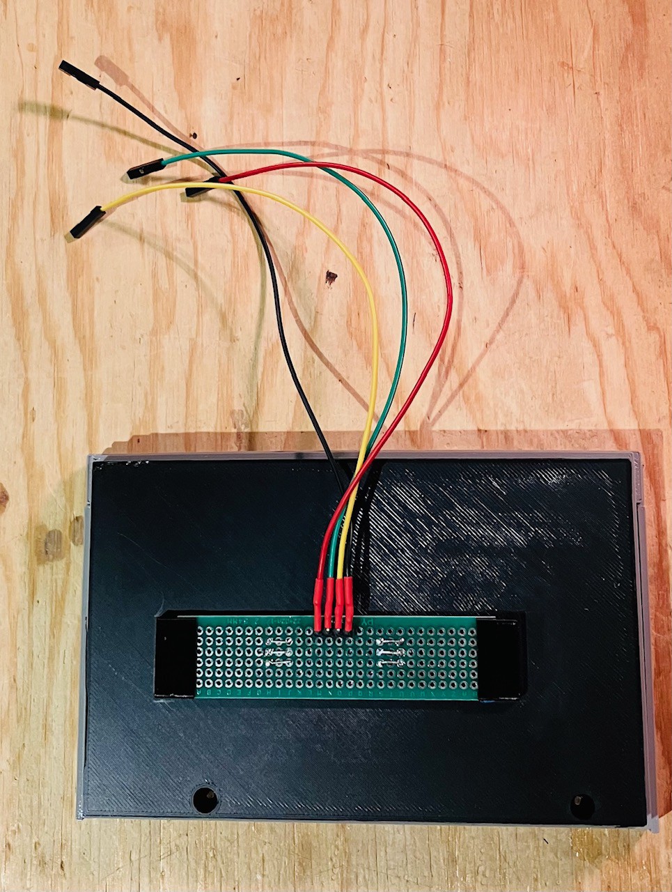
I connected the wired deck the an Arduino Nano and wrote a small sketch to test the reader. Here is the code.
/*
  Test MCM/70 Tape Reading.
*/

int currentState = -1;

// the setup function runs once when you press reset or power the board
void setup() {
  // initialize hall effect sensor digital pins.
  pinMode(5, INPUT_PULLUP);
  pinMode(6, INPUT_PULLUP);

  Serial.begin(115200);
  Serial.println("Test start...");

}

// the loop function runs over and over again forever
void loop() {

  int fiveState = digitalRead(5);
  int sixState = digitalRead(6);

  if (fiveState == 1 && sixState == 1 && currentState != 3) {
    if (currentState >= 0) {
      Serial.println("Eject");
    }
    Serial.println("No Tape");
    currentState = 3;
  } else if (fiveState == 0 && sixState == 0 && currentState != 0) {
    Serial.println("Empty Tape");
    currentState = 0;
  } else if (fiveState == 1 && sixState == 0 && currentState != 2) {
    Serial.println("Utils Tape");
    currentState = 2;
  } else if (fiveState == 0 && sixState == 1 && currentState != 1) {
    Serial.println("Demo Tape");
    currentState = 1;
  }
  delay(500);                       // wait a bit
}
Here is a short video of the test.
Looks like it's ready to go. I'll incorporate the cassette into the Emulator code when I start integrating all of the finished pieces into the final build.
Discussions
Become a Hackaday.io Member
Create an account to leave a comment. Already have an account? Log In.