Problem: Upgraded graphics card and 4 year old PC keeps crashing intermittently.
Analysis: My graphics card consumes a maximum of 350W, cpu is an i3 8100, either 45W or 65W sku. Crashes were happening about once a day, seemingly at random. Eventually found a point in Valhiem where it would consistently crash while rendering a thunderstorm.
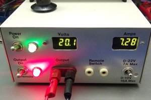
My PSU is rated at 650W and can deliver 44A to the 12V rail (528W), theoretically this is enough for the GPU and CPU and this is why I felt comfortable that the following modification was safe to make. So why was it crashing? My theory is that the current draw when the GPU engages boost mode is significantly higher than what can be supplied instantaneously, so the 12V drops below the low-voltage protection limit and this triggers the reboot. Alternatively the culprit could be Over-Current-Protection on the PSU. Either way, this solves the problem by creating a buffer on the 12V line to supply the current the GPU needs and gives the PSU time to respond to sharp changes in demand from the GPU.
Solution: Buffer the GPU's power demands to stabilize the 12V rail voltage and still supply the GPU with all the current it needs.
You need lots of capacitance, a prototyping board to mount the capacitors on and wires.
I used 18AWG wire that I got from other modular power supply cables I wasn't using and won't be needing. I also used some fine gauge wire to mechanically fasten the groups of wires to the prototype board so they wouldn't move around while I was soldering. I recommend pre-tinning the ends of wires you will be soldering to the prototyping board.
18AWG didn't fit through the holes on my board so everything is retained by the capacitor leads and fine 30 AWG wire / 24 AWG artistic wire. (The 30 AWG wire was actually better and easier to use). Any stranded wire can be broken down to get fine guage wire to use for this purpose.
STEP 1:
Put capacitors on the prototype board.
STEP 2:
THINK! How will this be installed when you finish? Where will it go? How long do the wires need to be? How will you make this removable if you need to make modifications / repairs / upgrades later?
(If your wires aren't long enough you need Step 2.5:
STEP 3:
Attach wires to 12V and Ground. If you have two 8-pin connectors to your video card then this is 16 wires from your PSU and another 16 wires to your GPU. See the schematic and pictures.
STEP 4:
Add Bus wire. There is a lot of current moving between the input and output of this board. At times it might exceed 30 amps! For safety and performance, we need a BUS. 12 AWG wire is what I used, there might also be terminal blocks out there that could serve the same purpose. A very powerful soldering iron set to maximum temperature will be needed to properly and fully flow solder down the length of the 12 AWG wire. What I did was take some stranded 12 AWG wire I had for quadcopters and took a length of about 3 inches (7.5cm) and stripped the middle 5cm (2 inches) of it. This way there was still some insulation at the ends to keep the strands together. I used clamps on these insulated ends to hold it to the circuit board while I soldered it on.
STEP 5:
Electrical tape. The 12V and ground need to be insulated from each other and everything else (such as metal computer cases). Bundle up your wires in to input and output bunches. Then apply the electrical tape over all your beautiful clean shiny solder joints and wire. I applied it in layers in alternating directions, looping around the board where possible to make sure my equipment is protected.
STEP 6:
Install it! Take care to not mix up ground with 12V. If you used yellow for 12V and Black for ground then this should be very easy.
STEP 2.5: make wires longer.
Cut off the last 4 to 6 inches (around 10 to 15 cm) of the GPU power connector cables. Save both parts....
Read more »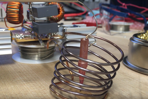
 jdunbar360
 Quinn
Quinn
 serdef