cafelizardo
2014 - Birth Of A Game Cabinet
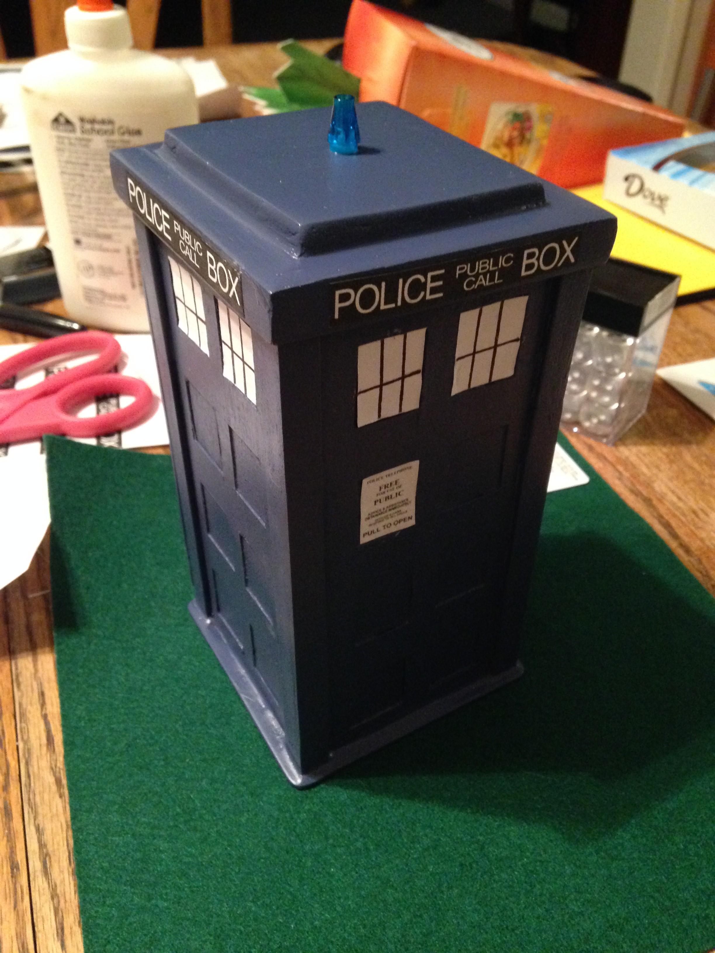
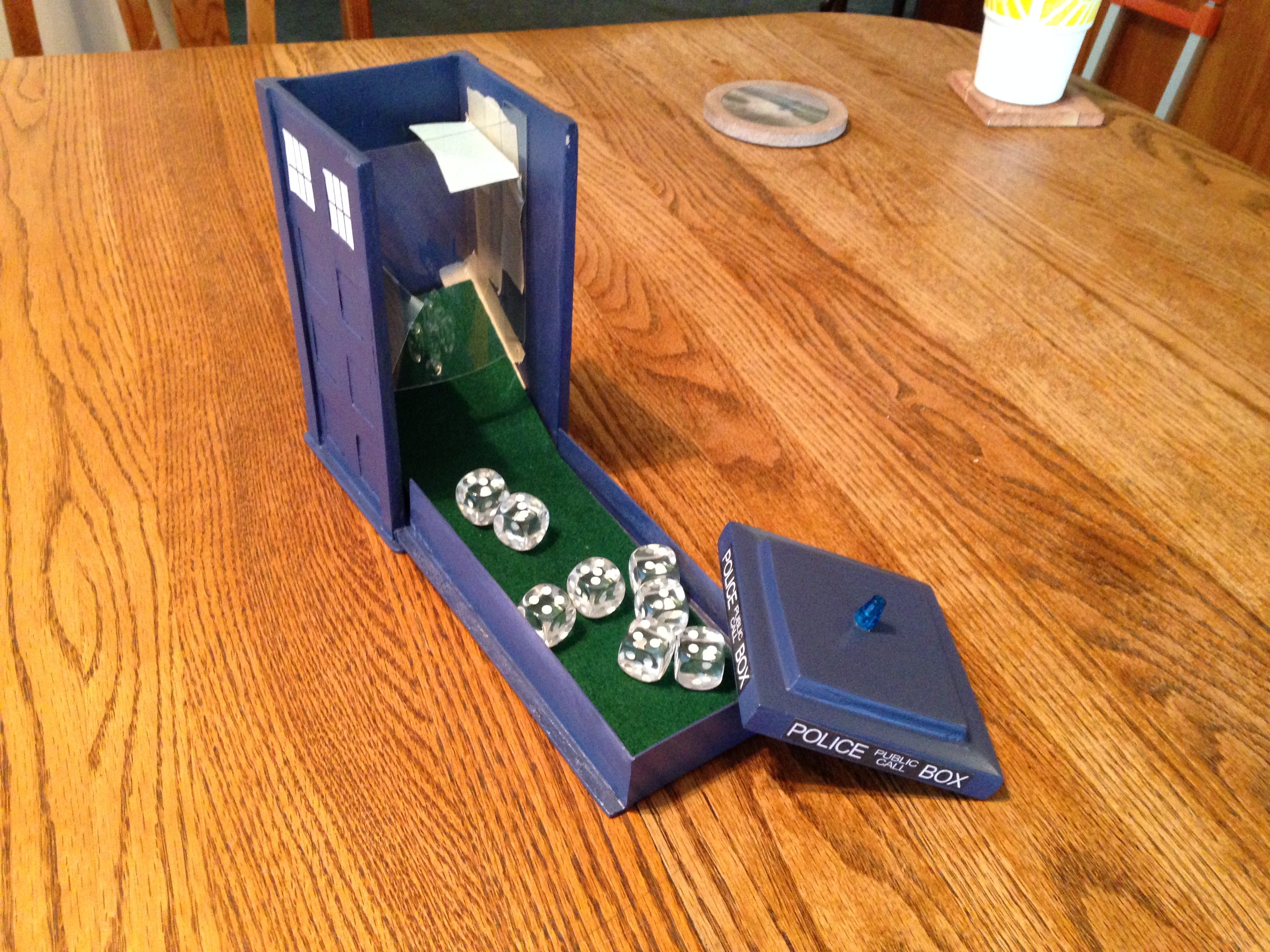
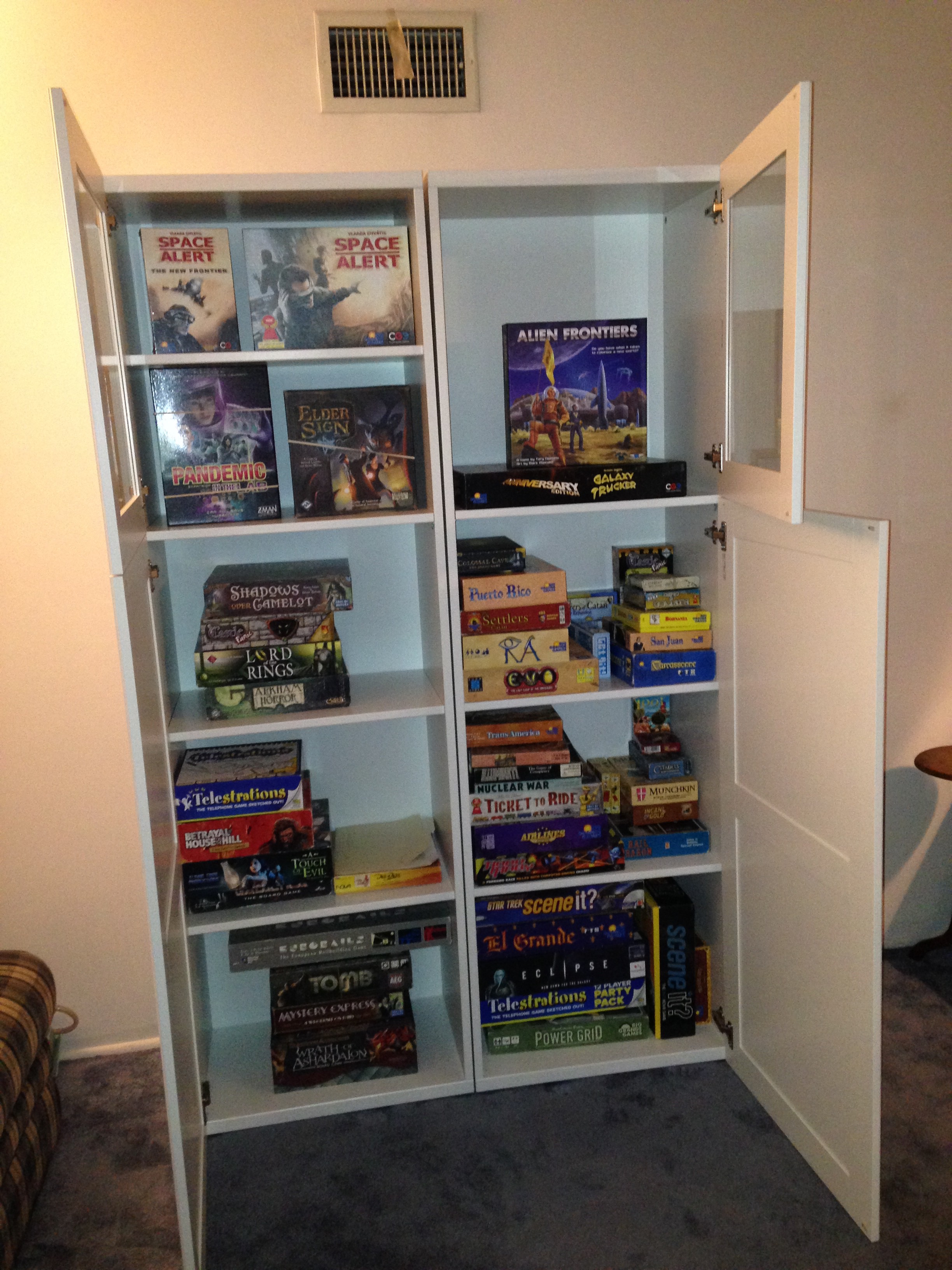
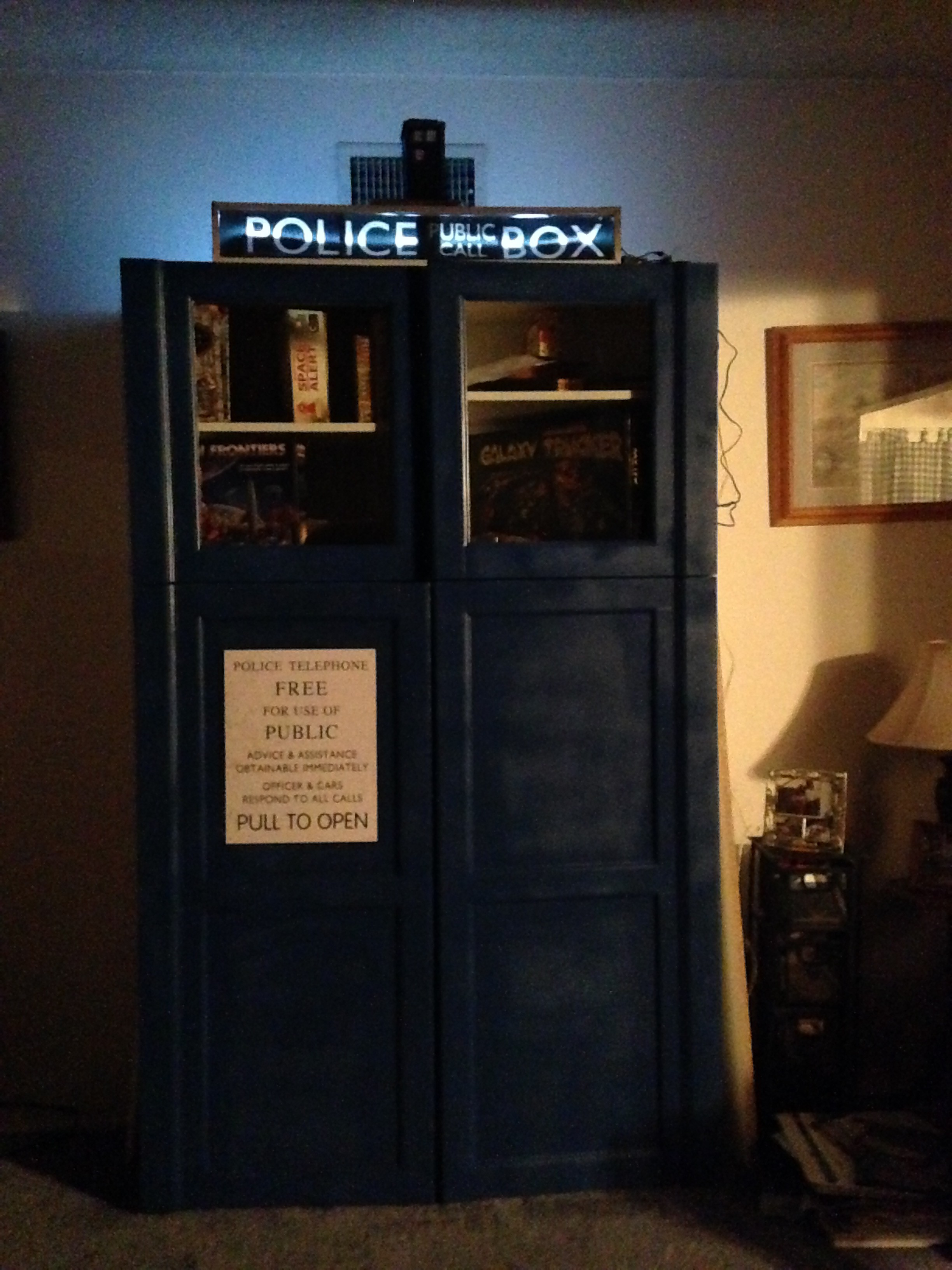
Our game collection was stored in various milk crates and other storage chests throughout the house. My wife suggested shopping around for a tall cabinet and after looking around I started to get an idea. I had made a TARDIS themed dice tower and thought we could do something similar.
 |  |
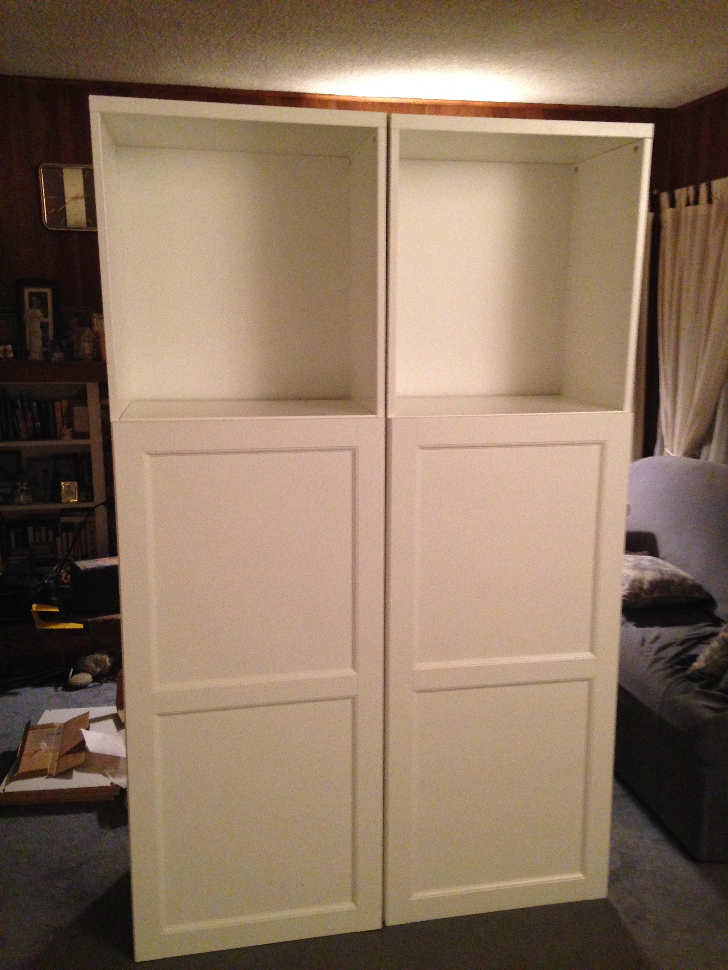
Some of the cabinets we looked at looked very nice but we didn't want to spend a lot if we were going to repaint it. Found some cabinets with doors at IKEA that looked like they might work. Measuring approximately 24" wide by 16" deep by 76" tall we picked up a pair so we could put everything in a single place.
 |  |
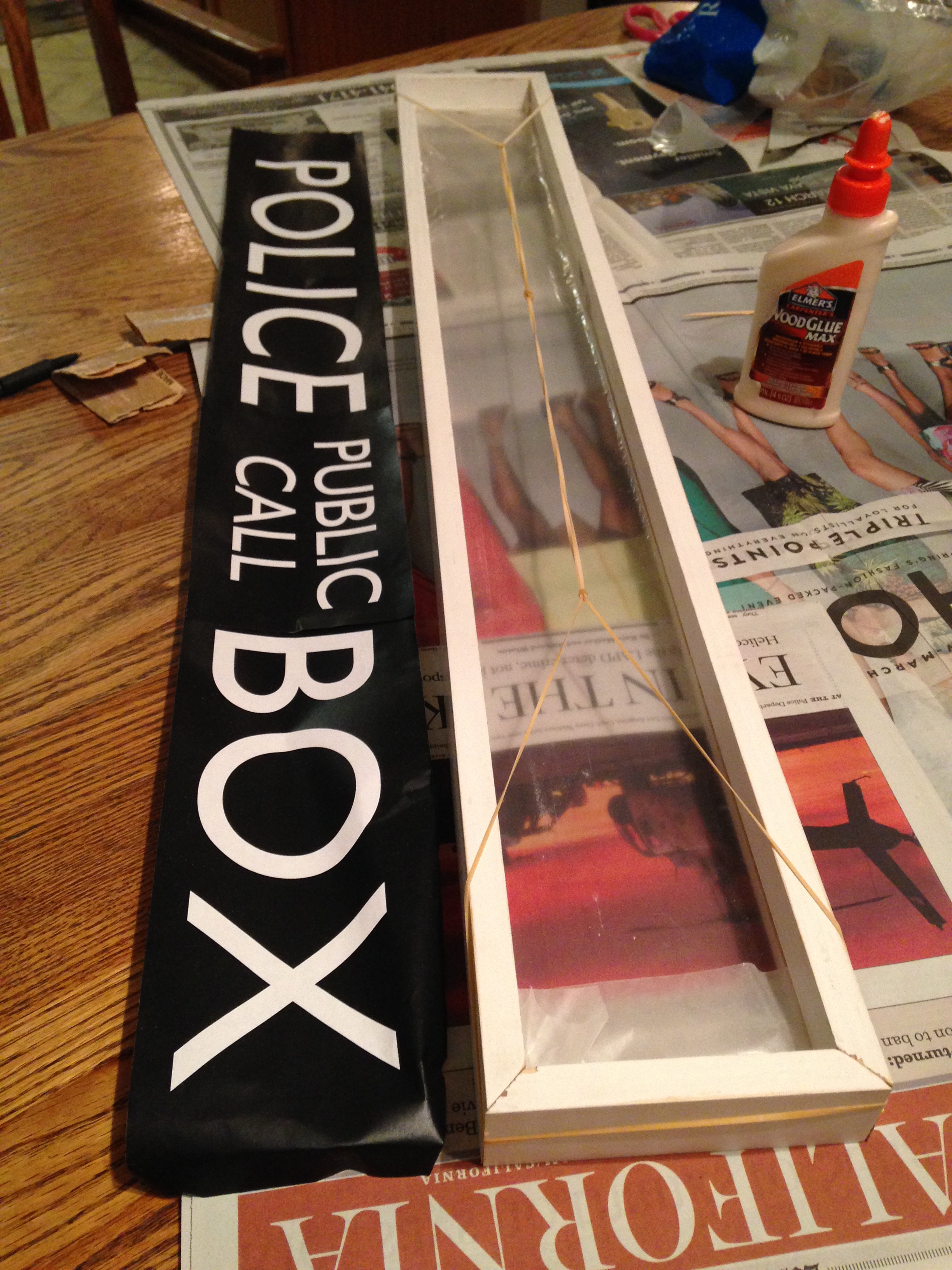
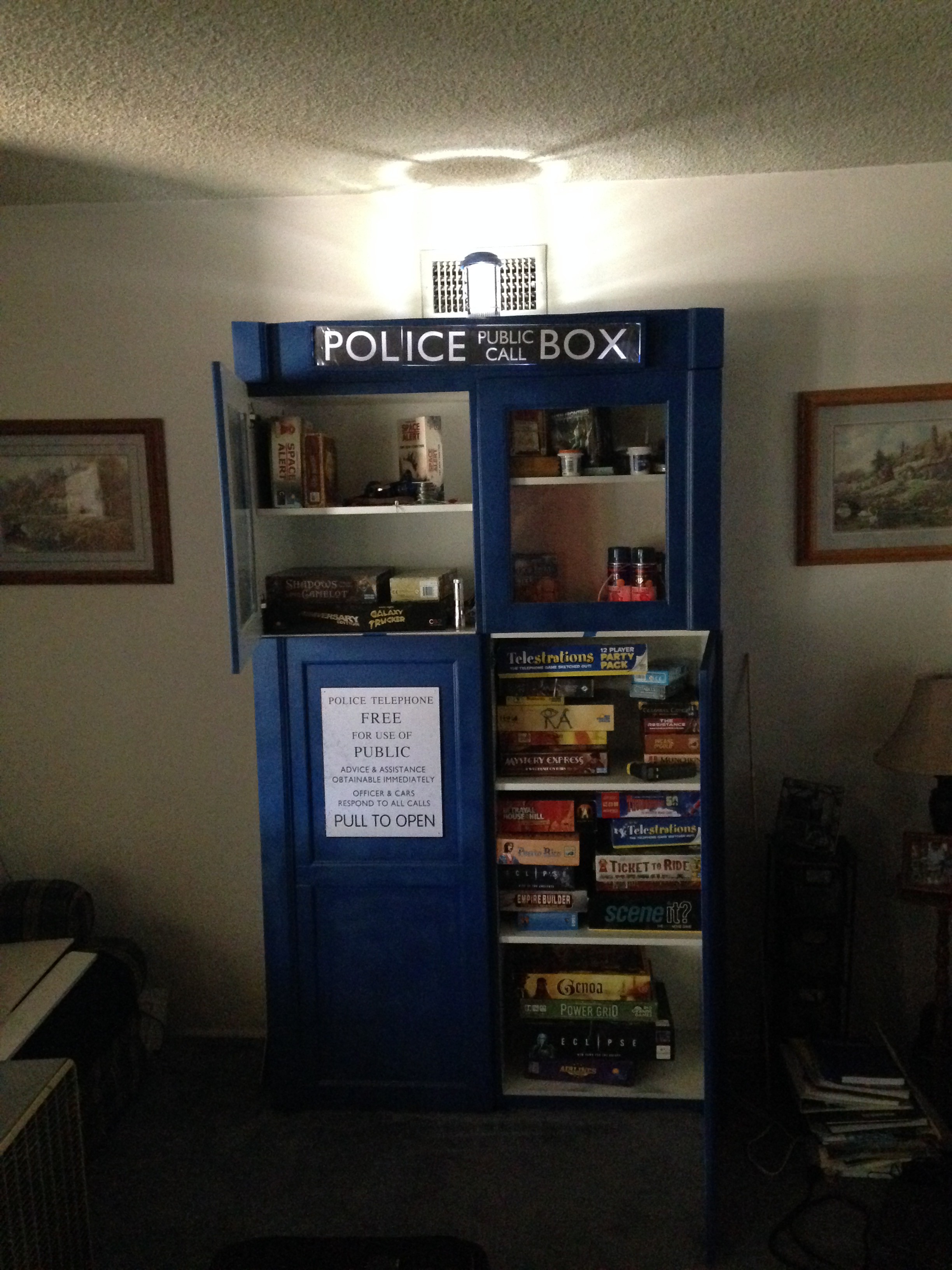
I made a box frame for the "Police Public Call Box" sign with a slot for the plexiglass. The print itself is just a couple of pages from a laser printer taped together. I also added some extra trim on the doors to make it look like corner posts and added a facade on top to hang the sign. Royal blue seems close enough. My wife found the plaque online somewhere.
 |
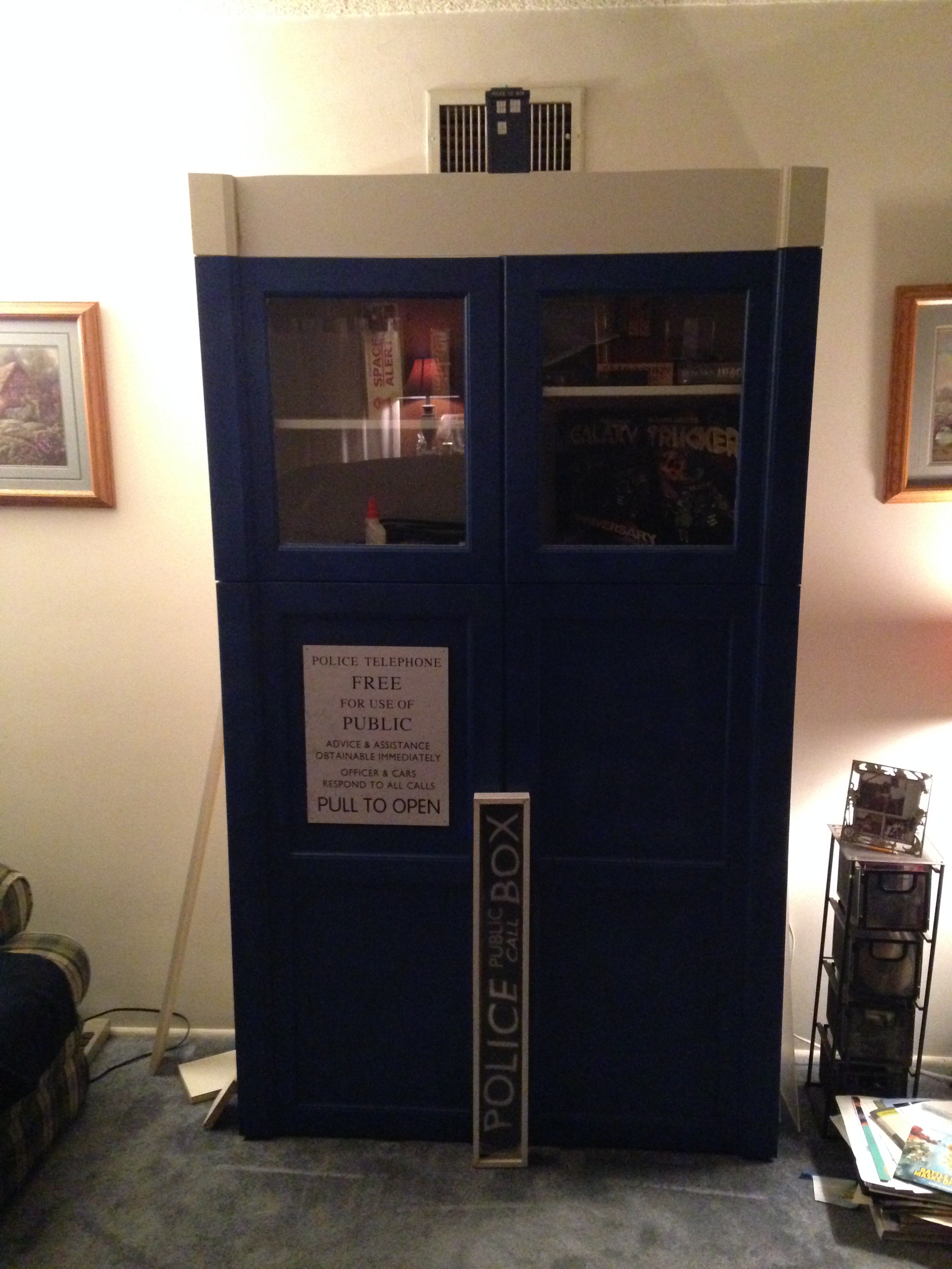 |
From the side it looks like a TARDIS has materialized partially into the wall.
2015 - Adding Lights And Sound
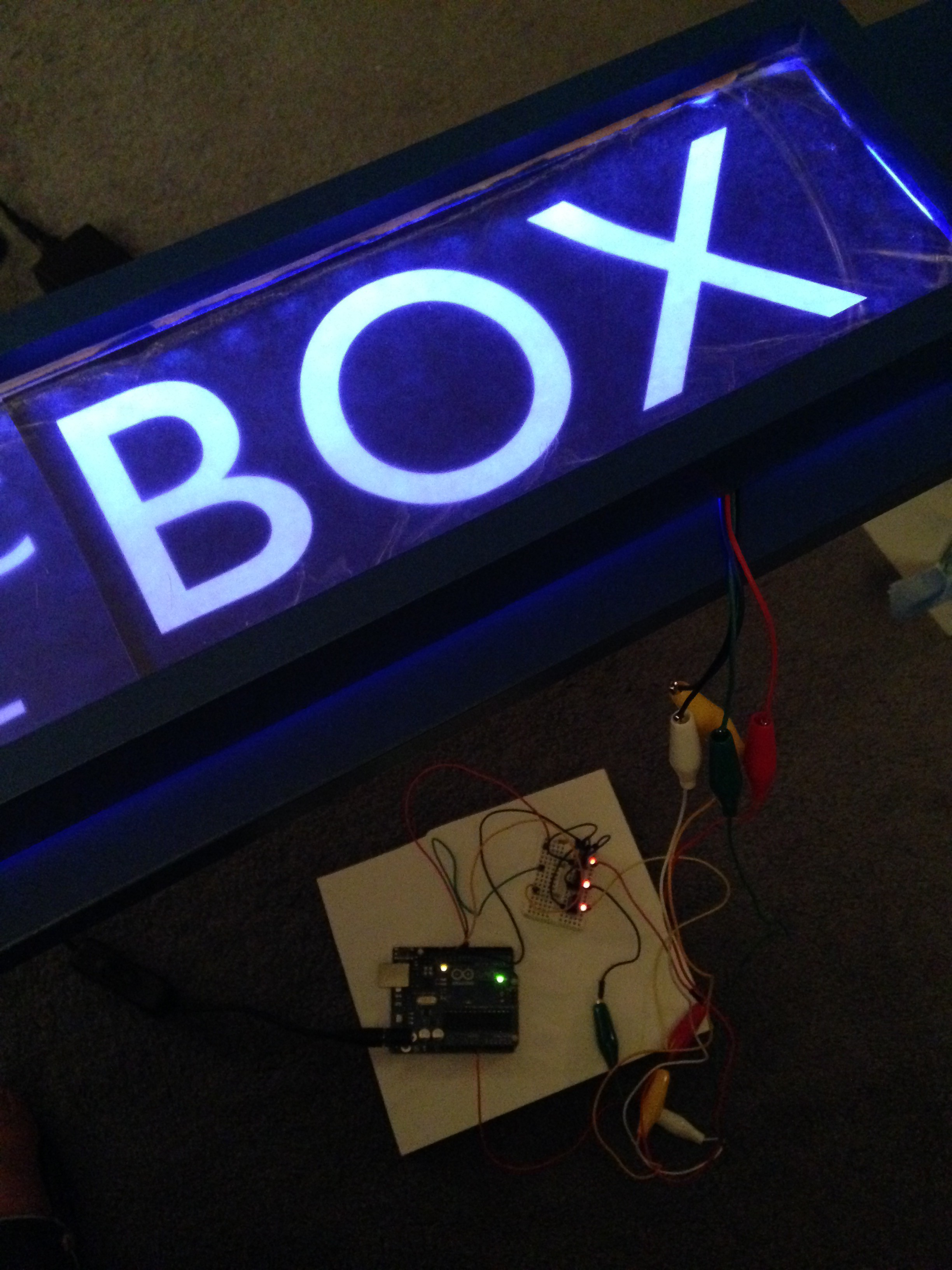
Started experimenting with different ways of lighting the sign. Tried an electrolumenscent light strip but it wasn't bright enough so starting looking at RGB LED light strips using MOSFETs controlled by an Arduino Uno. I used a 1 meter long non-addressable LED strip as the addressable strips were still pricey at the time and I wasn't sure how it would look. The strip is driven by 3 MOSFETs which are controlled by 3 PWM output pins from the Arduino. I started writing some code to fade the colors on and off giving it a pulsing look. I was pretty happy with how it looked. See below for some videos and the logs for some code snippets.
N-Channel MOSFET 60V 30A from Sparkfun
 |  |
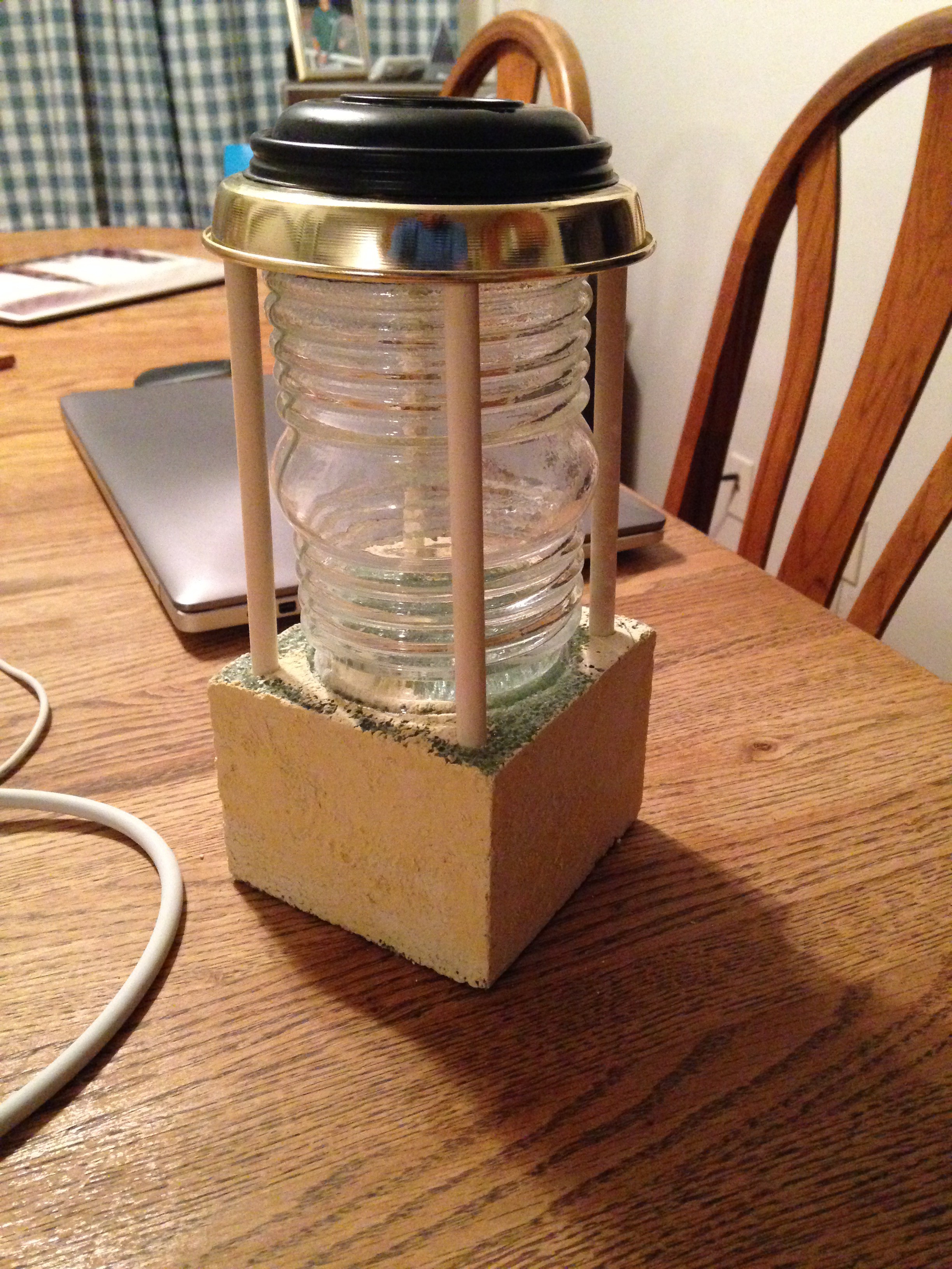
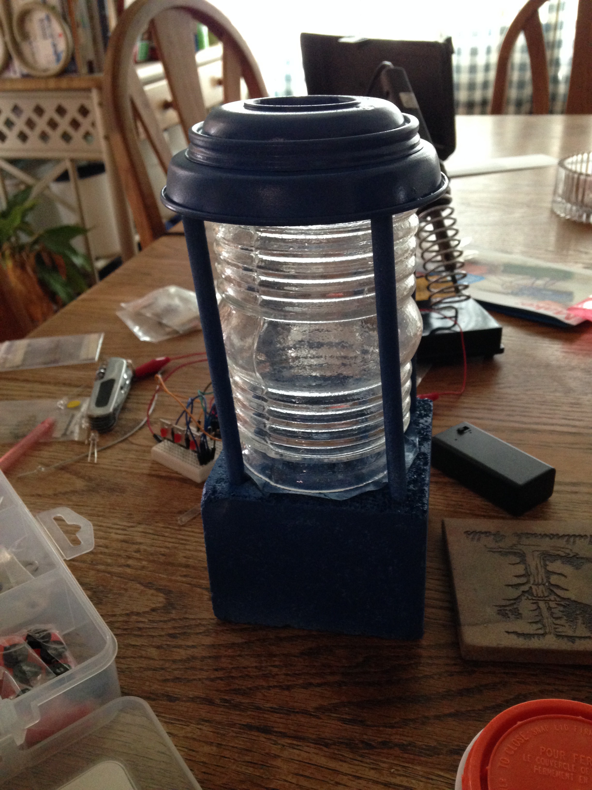
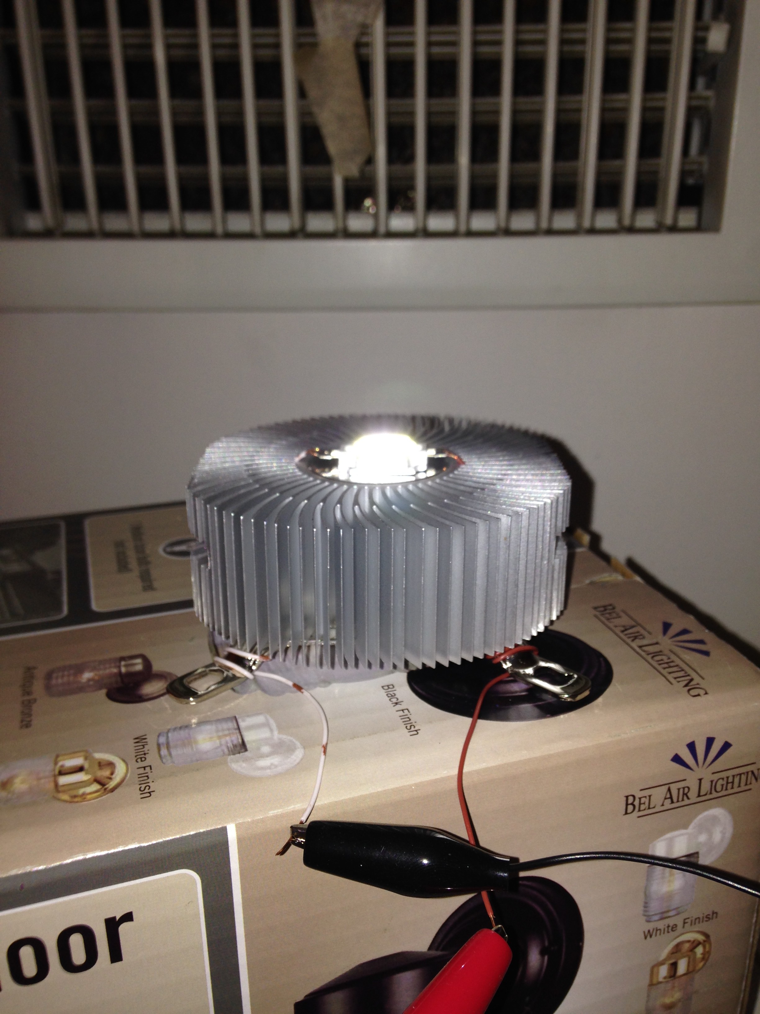
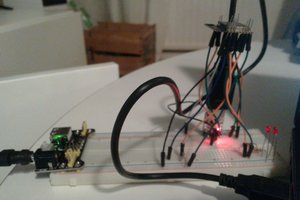
Also started working on the roof mounted beacon lamp and tried various ways to light it. I first tried stringing a bunch of LEDs but didn't like the way it looked so I found a high intensity LED array that worked quite nicely but it need quite a bit of power which meant heat. Yes, that's a cpu fan assembly with large fins that I found in my parts cabinet. No active cooling.
 |  |
 | 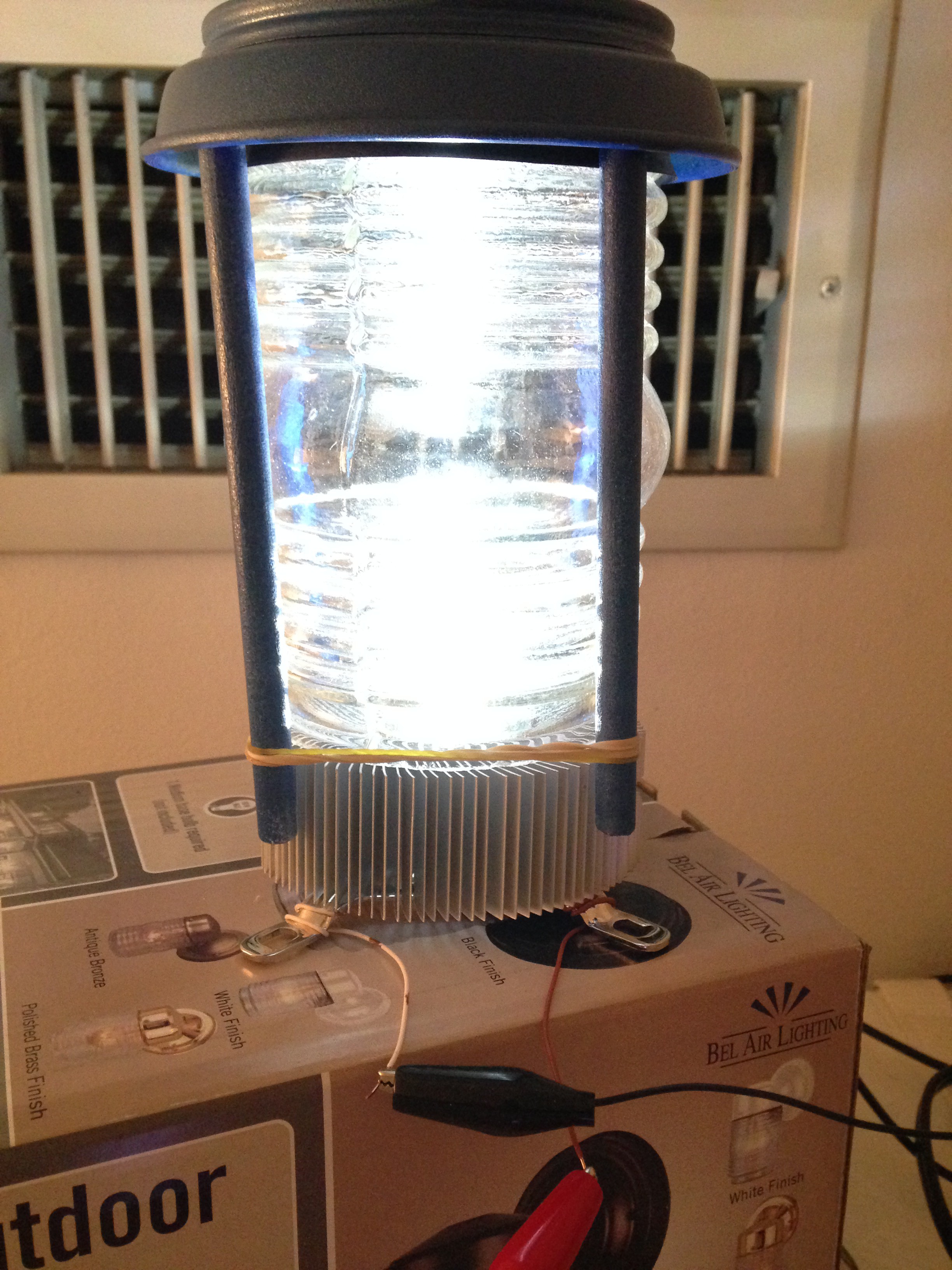 |
 | 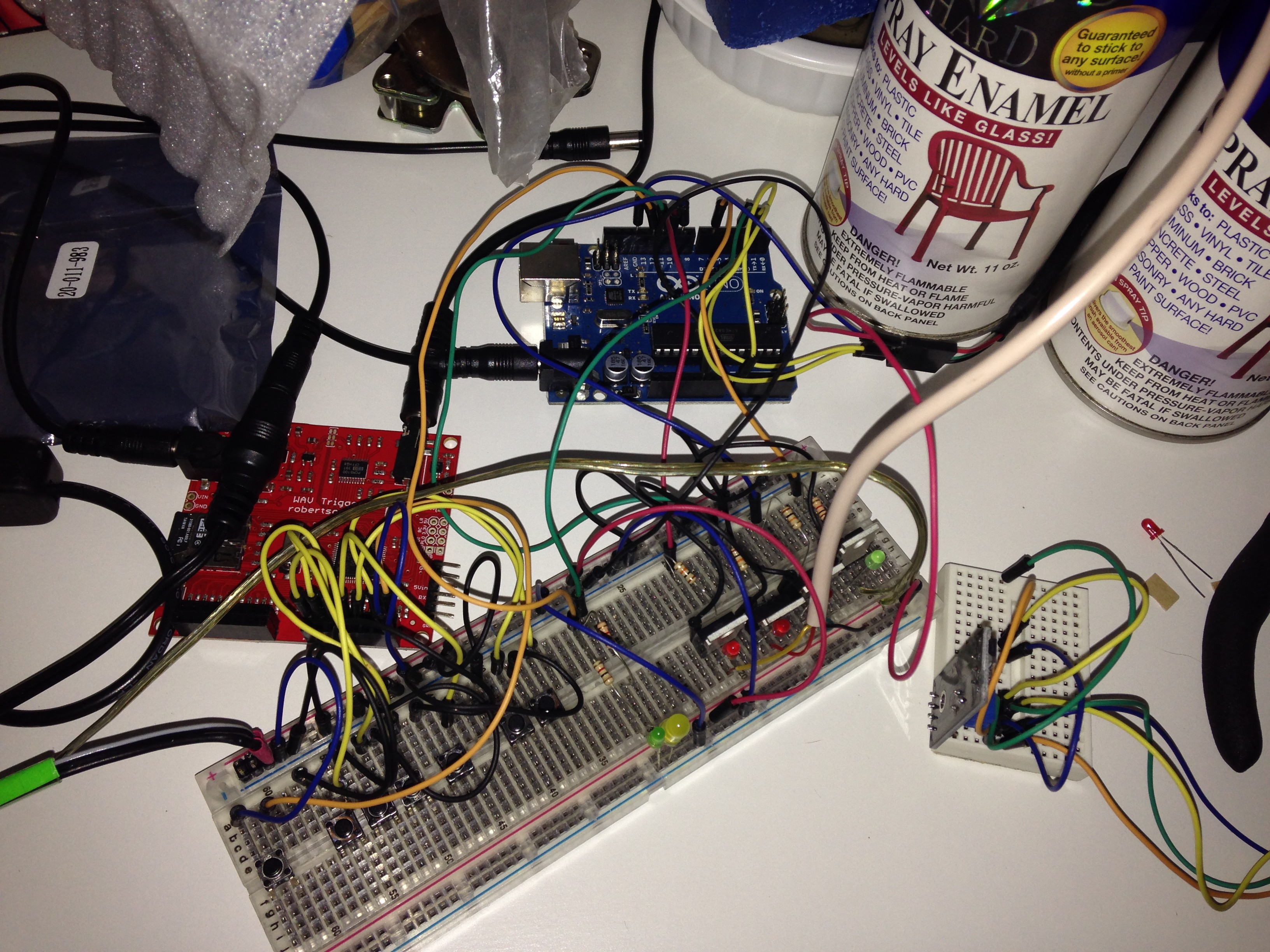 |
I then found this really cool WAV audio shield from SparkFun that has polyphonic sound and can be triggered either by grounding an input line or via MIDI.
Sparkfun WAV Trigger WIG-13660
See Logs for code snippets for controlling lights and audio board.
2016 - More Lights And Door Sensors
The top door on each side has a glass window so I added more RGB LED strips at the top and under the adjustable shelf behind a strip of wood to hide the LED strips. I connected these 4 LED strips to the existing strip for the sign. I also wanted a separate channel for the white LED in the roof lam so that driven by another MOSFET and controlled by another PWM output.
There are actually four doors and I wanted to add a sensor to each door. The idea was to detect the angle of each door so I could play a creaking door sound effect which would require 4 analog input lines.
At that point I was using 4 PWM output lines, several digital lines to trigger the various wave files and was looking at adding an IR sensor so I could use my Sonic Screwdriver TV remote to control the TARDIS which would be really cool but I was afraid of running out of I/O lines on the basic UNO. I could have switched to a Raspberry PI but that seemed like overkill and I thought I had read that there was a problem with driving PWM Chanels so I opted for an Arduino Mega which has plenty of I/O. However I couldn't figure out a way to reliably detect the door angles and adjust the squeak in real-time so I opted for magnetic door sensors using Hall effect sensors.
Magnetic Reed Switch - Insulated
At...
Read more »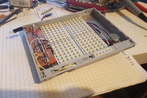
 davedarko
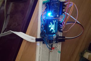
 Pauli Salmenrinne