 Wenting Zhang
View video about this project on YouTube:
I highly suggest watching the video. The following is the transcript of the video:
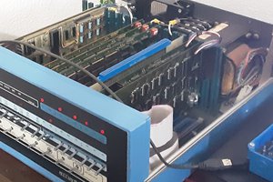
Hello everyone, it has been a while. This video I would like to share one of the projects I finished recently, ELterm. Which stands for electroluminescence terminal. I bought these Planar 640 by 480 electroluminescence screens a few months back. The display is sort of similar to OLED, but it’s monochrome. These dot matrix screens typically emit yellow or amber ish color, but there are also models which are red and green dual color. Naturally I want to make something with this screen, and I decided to make a serial terminal with it, so let’s get started.
This video contains the following parts:
- Processor selection and overall design
- Making the hardware
- Writing the driver for EL screen
- Implement the serial terminal
- Final result
First is about the processor selection. I would like to implement the whole thing with just a microcontroller. The serial terminal part should be okay, the original VT220 was based on a microcontroller anyway. But refreshing the screen might not. Most of the dot matrix display technology requires constant refreshing, like at 60Hz. Screen modules that’s commonly used with microcontrollers are self-refresh screens. The screen module has its own memory and controller, and would refresh from its own memory without microcontroller intervention. For example, like these OLED modules, while the OLED needs constant refreshing, I could just disconnect the microcontroller, and it keeps the display. There exists self-refreshing EL screens, but the one I have isn’t. It demands to be refreshed at 120Hz, which means the microcontroller needs to continuously push data to the screen at 120Hz.
This put some requirements on the microcontroller. It would either hold the entire framebuffer in the RAM, or it could generate image data at screen refreshing speed. Both works, but bing able to store the frame buffer would be a bit more flexible. Then it should be able to generate the timing needed by the screen. Obviously one could do this with an FPGA, and I do have an FPGA video coming up in the future, but that’s for another time. For this time, many of the 32bit microcontroller works here, I chose the RP2040 from Raspberry Pi.
Here are the main spec for the RP2040. Dual-core Cortex-M0, 264KB SRAM, no internal Flash, executes code from SPI flash. The most important part for this project is it has PIO, which is a micro-code programmable IO module. I will show how to use it to drive the screen.
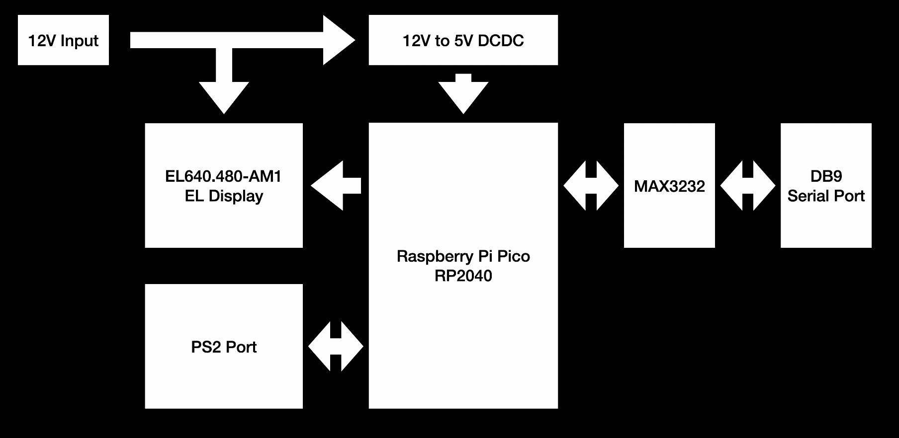
Now let’s take a look at the overall design. With the microcontroller in, I just need to fill in the interfaces I need. The screen doesn’t need any extra interface chips, and could be connected directly to the microcontroller. The terminal needs keyboard input, so adding a PS2 port here. Of course I could also just use the USB port of RP2040 itself. At last, the terminal needs a serial port, so adding a MAX3232 for a RS232 port, with jumpers for TTL serial options. For the power supply, the screen has internal high voltage generation, so only a 12V is needed. I decided to use 12V input for the whole board, and then use a 12V to 5V DCDC to power the Raspberry Pi Pico.
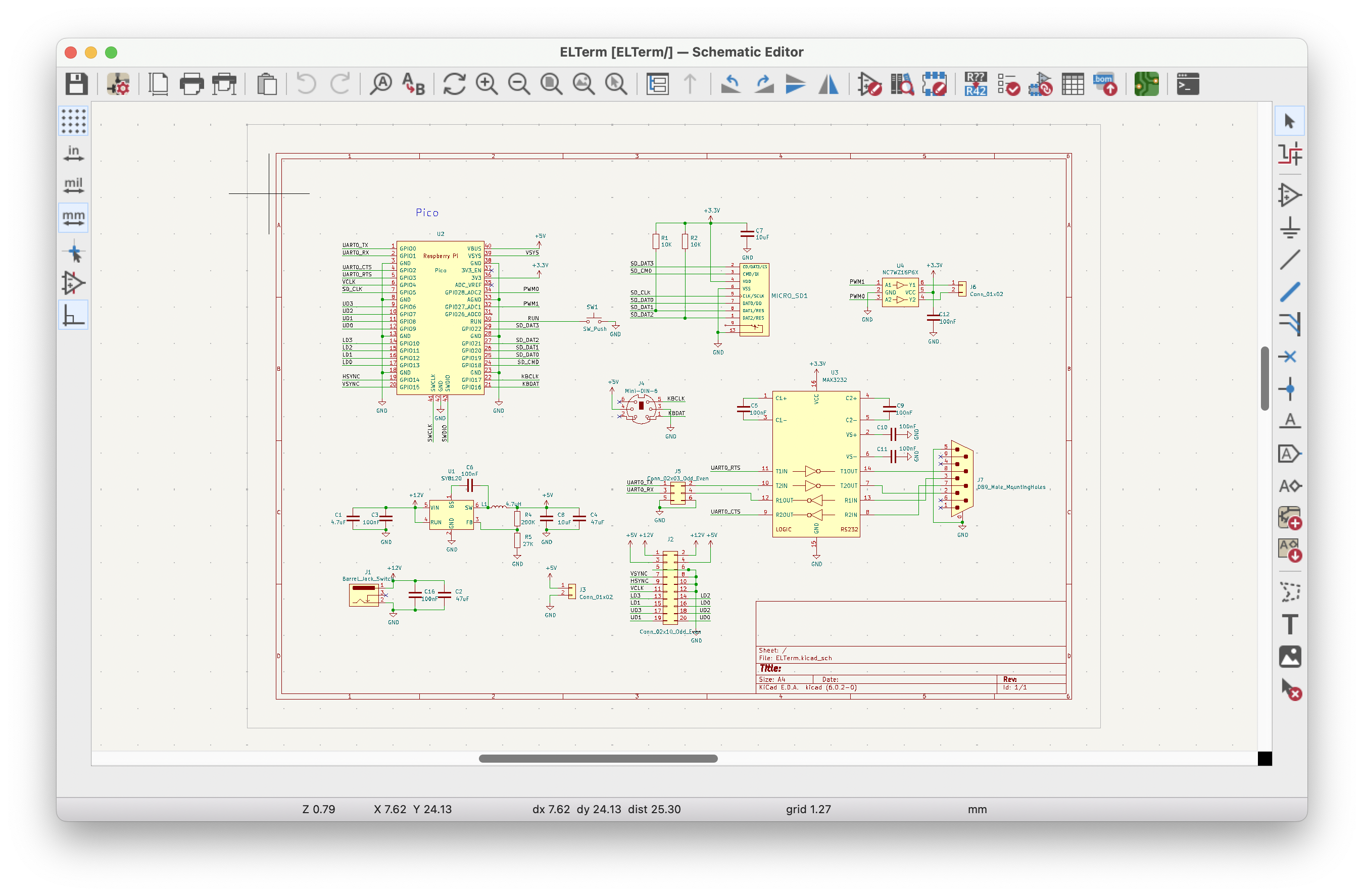
Then comes routing the board. To keep things simple, I am using the Pico as a module and mounting it directly on the board. There isn't much special about this board. So I am not going into details.
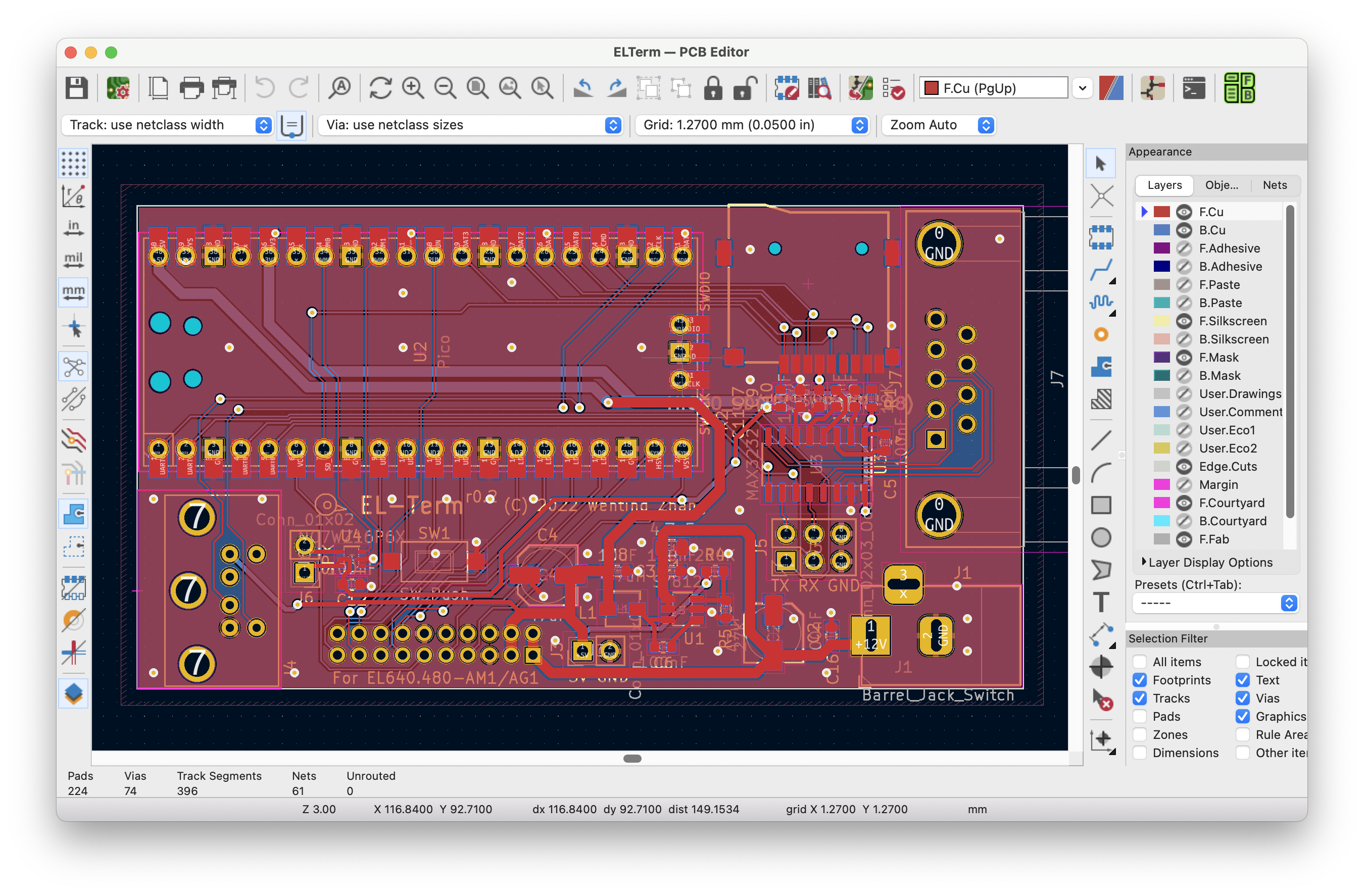
Once done, exporting the Gerber, submitting to the manufacturer, and a few days later I got the board. Then soldering the board. I usually solder the capacitors and resistors first, then chips, and last the connectors. There isn't much stuff on this board, and to be honest, I have been mostly working on more complex boards like with FPGA or SoC or DDR, and it’s refreshing to work with these simple 2-layer microcontroller boards again.
Now it’s time for coding. First about the screen driving. There are clear timing requirements in the screen datasheet....
Read more »
 glgorman
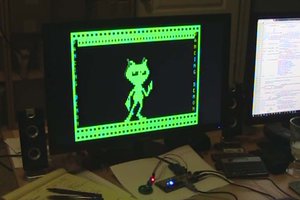
 ziggurat29
 Samuel A. Falvo II
 Nicola Wrachien
Is possible runing fizix system on this device?
how long this device work on one charge?