 James Newton
What if I told you it was possible to SAFELY use ANY SmartPhone as a robot brain?
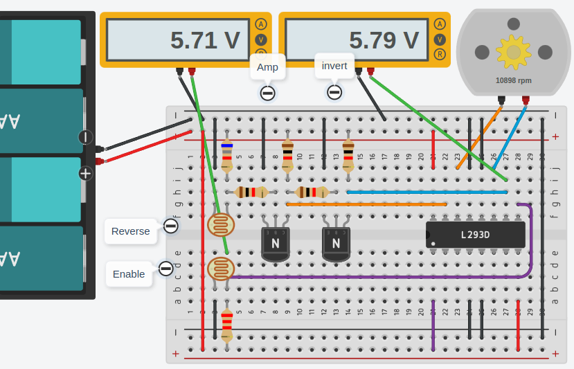
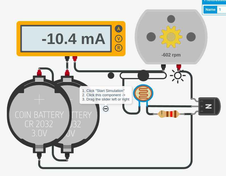
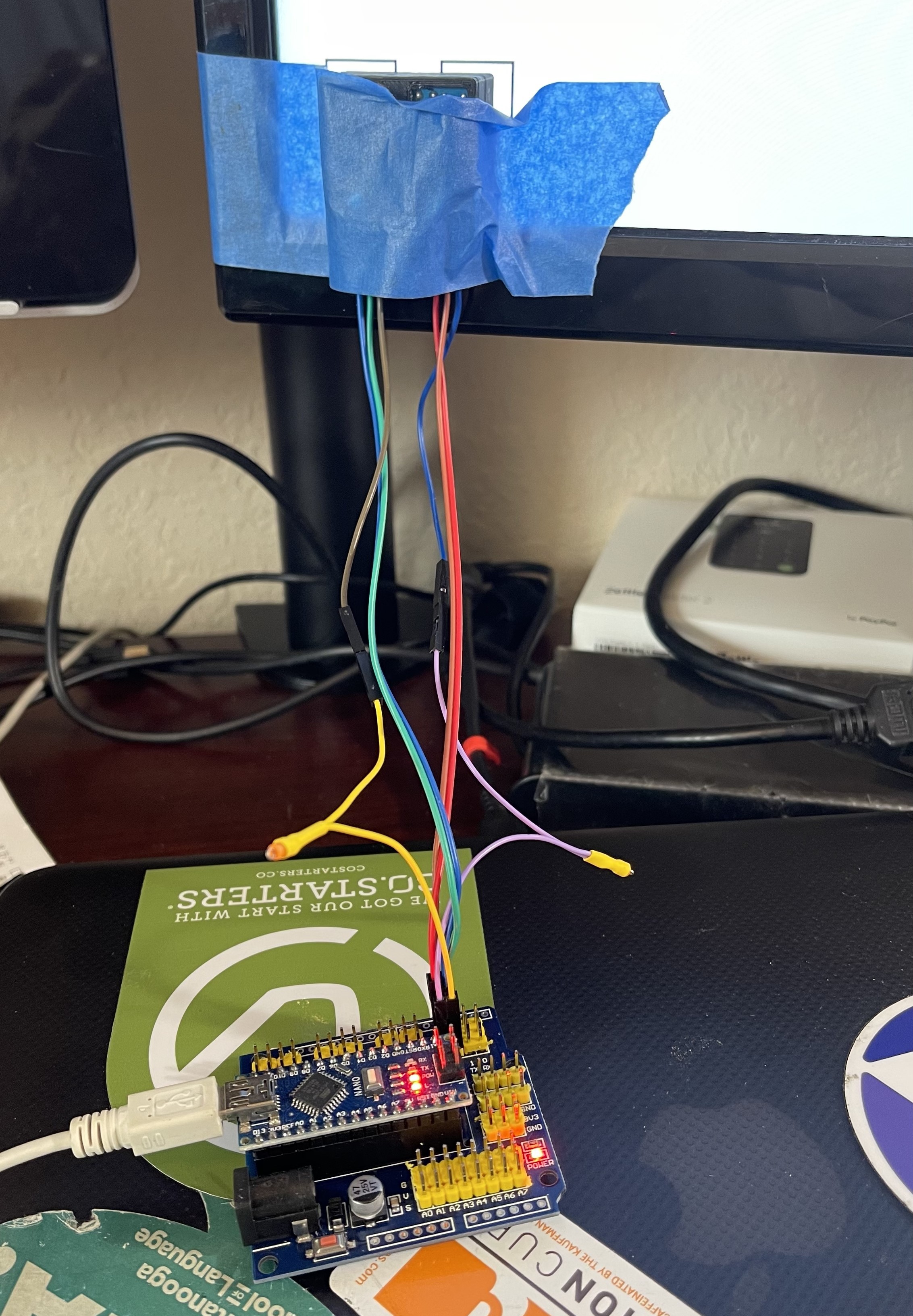
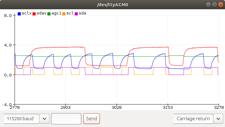
On any smartphone with a browser, load a freely hosted github.com webpage with Javascript that blinks areas on the screen to send motor commands to an e.g. Arduino. The page can also access web services API's for voice, object recognition, teleoperation, etc... via WiFI or Cellular data.
- Safe: No electrical connections to the phone, so you can't possibly damage it.
- Any SmartPhone: Not dependant on any hardware support; doesn't need USB, audio jack, BLE, anything.
- Secure: No app needed, so no security concerns, no development software required, nothing to learn but Javascript.
100% reliable, no configuration, easy debugging because everything is visible.
- Sensors: You still get access to all the sensors on the phone; camera, accelerometer, compass, GPS, and to the web via WiFI or cellular connection.
- Internet: You can remote control it, or have it log data, pics, etc... It can access online services for object reco, voice APIs, etc... but no for $ service provider is required; it's free.
- Stunningly Cheap: Total additional cost, beyond a tiny circuit or a cheap mcu (Arduino, Pi Pico, etc...), dc motors or servos, battery, whatever else you use for the robot, is pennies. All open source, no required services, no BS.
History: ESP's web servers provide great UI's on SmartPhones
The San Diego Makers Guild has provided literally hundreds of low cost robots to kids at events. These are based on the NodeMCU (ESP32 or 8266) devices, with a couple continuous rotation servos and a battery pack, programmed with a web server accessible via direct WiFi connections, which allowed them to be controlled by a web page on a cell phone or PC. There are many advantages:
- $5 chip, a pair of $5 continuous rotation servos, and a $2 battery pack. All the display, controls, user interface, etc... are on the SmartPhone
- Very clean, responsive, and fun remote control interface, without any app to install; just uses the browser on the phone. This video explains it pretty well. It's from a time when we were using the bots in a combat league.
- You can serve any static web page, so not only the basic remote control interface, but also your own custom version, settings, and even a simple web based IDE to edit the files on the ESP; it becomes a mobile webdev platform!
The use of the ESP chips to host web pages for smartphones is a great trick but... it's a bit of a trap, in that it's limiting.
Historical problems: No web services, no access to sensors:
It doesn't allow one to use the phone to contact the internet in general, and worse than that, you can't put the phone ON the robot /and/ use the sensors in the phone from a web page unless the web page is https with a valid certificate. The browsers security won't allow it.
Which means you either have to write an app, or install a cert on the ESP (nightmare) or connect the ESP to your house WiFI (which is VERY insecure and just a general bad idea) or... you have to just live without the camera, mic, accelerometers, GPS, compass, etc... all the wonderful sensors that the phone can give us. Which is a huge loss, because they can tell the robot what is around it, that it bumped into something, what direction its moving, where it is, etc.. Not to mention sending pictures to google for classification of objects or sending sound to recognize verbal commands, etc...
If not WiFi...
Instead, let's connect the smartphone to the robot some other way so we can still just use a web page, avoid an app, and run on the net. But what ways can we connect?
- Bluetooth Low Energy is horribly unreliable. Getting every model of phone to pair correctly is a nightmare, and... sending data from a web page to a BLE device isn't supported anyway. And you need a microcontroller that supports it, so it really limits your choices.
- We could use Bluetooth...


 minifig404
 Joshua Conway
 Cees Meijer
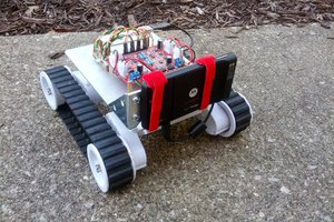
 Jason Bowling
I've been looking into twisted string actuators for use in any setup where the cell phone can be used to track an APRIL tag so that force type actuators are being used. Visual servoing.
https://patents.google.com/patent/US9272425B2/en
Given a material for the "string" with just the right properties, it will actually unwind on it's own, which means you don't even need an H-bridge for the actuator; a simple single transistor driver will do it.
https://docs.google.com/spreadsheets/d/1n7-rFFa2A_Ioa8paRK7CPpTLl38DlTkTA7gaNKXrrYw/edit#gid=0
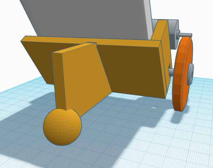
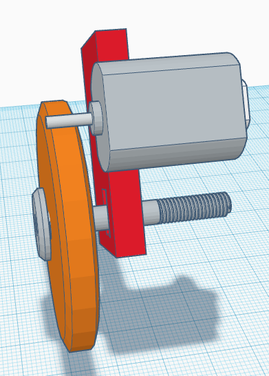
But... the other option is good old h-bridges and gear drives. I like worm gears. Really good ones can be 3D printed, but the plastic isn't that strong.
https://www.thingiverse.com/thing:2776688
https://github.com/chrisspen/gears
Metal worms don't cost all that much anyway.
I have this crazy idea that a metal worm could have a notch cut in it, and then be used to cut the driven gear from a disk of delrin, fiberboard, phenolic or carbon fiber. Something that will chip away but otherwise be very strong. But that isn't needed for a small version.