Jeroen Brinkman
Twilight switch clock
The clock uses a Real Time Clock (RTC), a light sensor, an Arduino Nano, a LCD display and a relay to make it work. For durability reasons an aluminium case is used, however it could also be placed in an 3d printed case. Construction is very simple, because the twilight clock only uses standard, off the shelve, components. So no PCB manufacturing or perfboard soldering is required.
The clock has very sophisticated software:
- Switch the lights manually on or off.
- Select if the clock is off, uses time only, uses light only or uses time & light.
- The automatically adapts the time twice a year to support daylight saving time.
- The clock can (automatically) be compensated for RTC drift.
- Backup scenarios are available for malfunctioning RTC or light sensor.
- When no light sensor is detected, it will calculate the twilight time.
Casing
First the casing and light sensor sand need to be fabricated. Below you'll find the drill guide for the front of the aluminium casing.
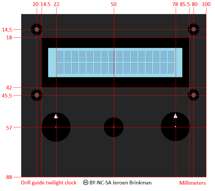
The drill guide for the twilight switch clock
In addition to the front, holes also need to be drilled in the left and right cover plates. One plate contains a hole for both the 220V cables and the other plate a hole for the RCA socket.
Light stand
After that the light sensor stand can be made. Two aluminum pipes from 80mm are required. One with a 30mm outer diameter and one with a 10mm outer diameter. 3D printing would be an alternative for this stand. A 10mm hole is drilled in the top middle position of the 30mm tube. The 10mm tube is placed inside this hole.
The LDR is desoldered from the sensor board and soldered on to a two-core wire. Be sure that both soldered wires are well insulated (use shrink wrap tube) and do not touch the aluminum tube. If more stability is required, some lead can be poured into the 30mm tube.
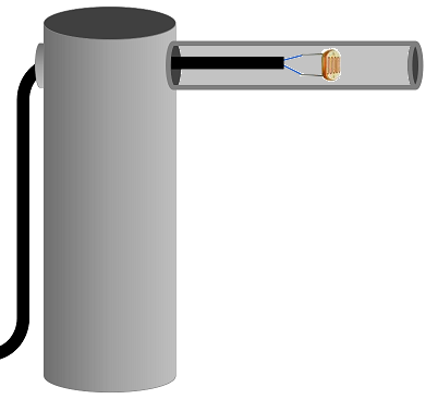
The light sensor stand
Then the components can be connected together as shown in the schematic below (Also see the documents of this project). The potmeter on the light sensor PCB needs to be desoldered in order to be replaced by a panel mounted potmeter. Be sure the 220V part of the schematic is well isolated, preferable by shrink wrap tube.
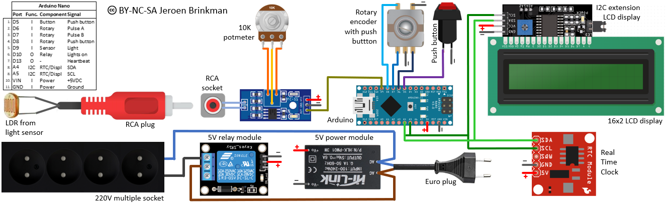 The schematic of the twilight switch clock
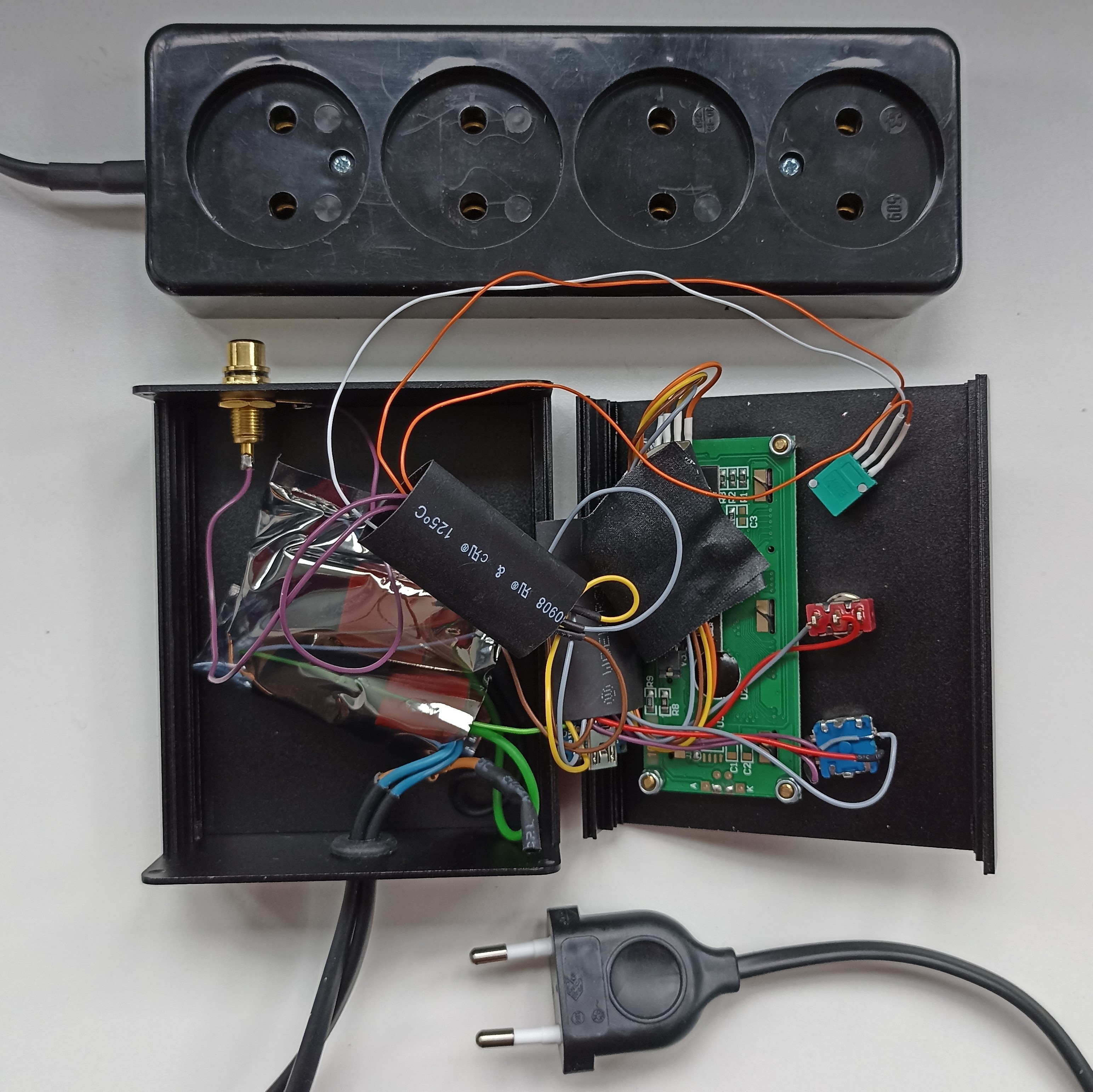
Inside the twilight clock
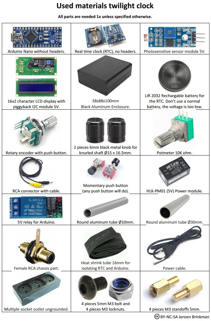
The used materials
 SephenDeVos
 Russell