 zpekic
Following stack operations have much in common:
- Turn all switches off (remember, MT8816 has a RESET signal so this can be done for all 256 at once, in one microcycle)
- Set up the 16*16 matrix according to the operation below
- Drive all registers around for a full round-trip (16 or 32 clock cycles)
Refer to the microcode for explanations below.
N[uke]
This is the simplest operation, all working registers are set to zero, with the "nuke" alias:
nuke .alias STATUS = busy_using_mt, MT_CTRL = clear;
When the STATUS microcode field is busy_using_mt, external "hardware window" on VGA has no access because the CPU is driving and picking up the switch matrix signals. MT_CTRL field is clear, which generates RESET signal for both MT8816 ICs.
MT_RESET <= 'Z' when ((mt_ctrl(8) and mt_ctrl(9)) = '1') else '0';
Z[ero]
Another simple operation, the nop1() subroutine connects Rx to Rx where x = 1..7, leaving R0 (TOS) unconnected. Because of pull-down to low, it means after a round trip of bits TOS will be cleared and all other registers unaffected.
Along with Nuke, Zero is the only command that also resets the error code register to zero ("no error") after divide by zero or invalid command errors.
// TOS <= 0, ERR <= 0 -------------------------------------
        .map 'z';    // "zero"
        .map 'Z';
// --------------------------------------------------------
        reset_flags, errcode <= ok, nuke, matrix_nop1();    // no switch on TOS means pull down, so it 0
exec:        div2(max, set);                                        // 16 or 32 *
done:        print_st();                                            // output stack top
        goto nextchar;                                        // go for next command
Note that due to both lower-case and upper-case Z pointing to same microcode entry point, commands are case-insensitive.
// rotate all registers right (LSB first) through switch matrix;
div2:		STATUS = busy_using_mt, opr = d2_d2_d2, c_flag <= adder, z_flags <= update, if bitcnt_is_zero then return;
		bitcnt <= dec, goto div2;
div2() subroutine uses the value of bitcnt register (which is initialized to value "max" resolving to either 15 or 31) and then executes a loop n time with registers driven to d2_d2_d2 control signals - so they all shift down and MSB bit is picked up from switch matrix.
S[wap]
Similar to nop, but TOS and NOS switches are swapped. Any number of registers could be swapped, copied, cleared etc. in one n-bit roundtrip.
[d]U[plicate]
TOS and NOS are clear, both will pick up value from TOS. Other registers are hooked up to "next one": R2 to R3, R4 to R5 etc. which means they will be "pushed" down, and R7 will be lost.
If "nop" is the diagonal, "push" is diagonal moved to right, and "pop" to left 1 register position. No stack pointer is needed.
R[otate]
It is like push, but R7 is connected to R0. This could be also viewed as one long 8*n length shift register, with n shifts all values are "moved" around.
<enter>
A simple push - because TOS is not connected to anything, it will get the "pull down" value of 0.
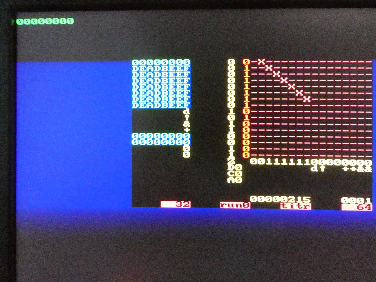
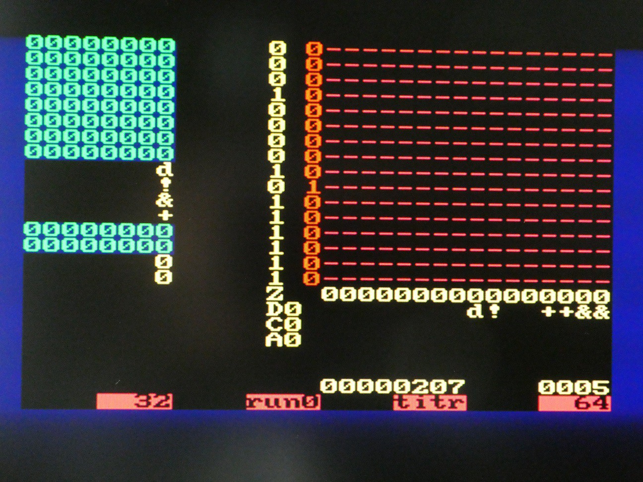
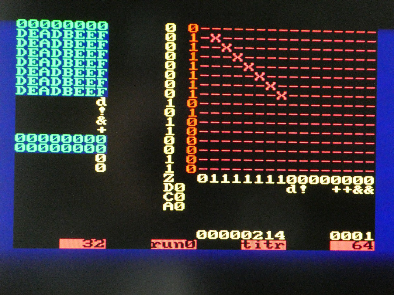
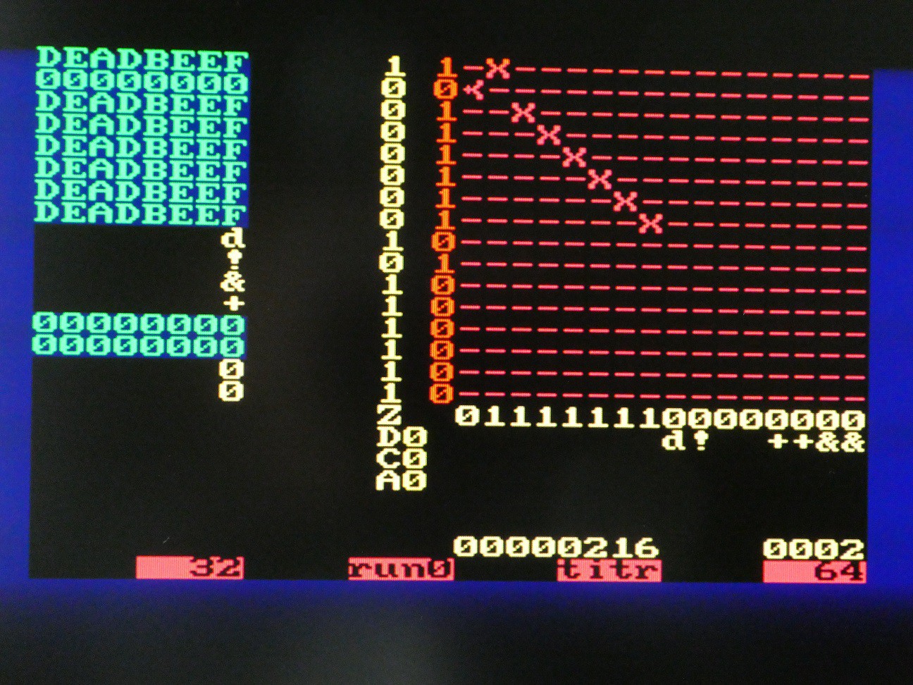
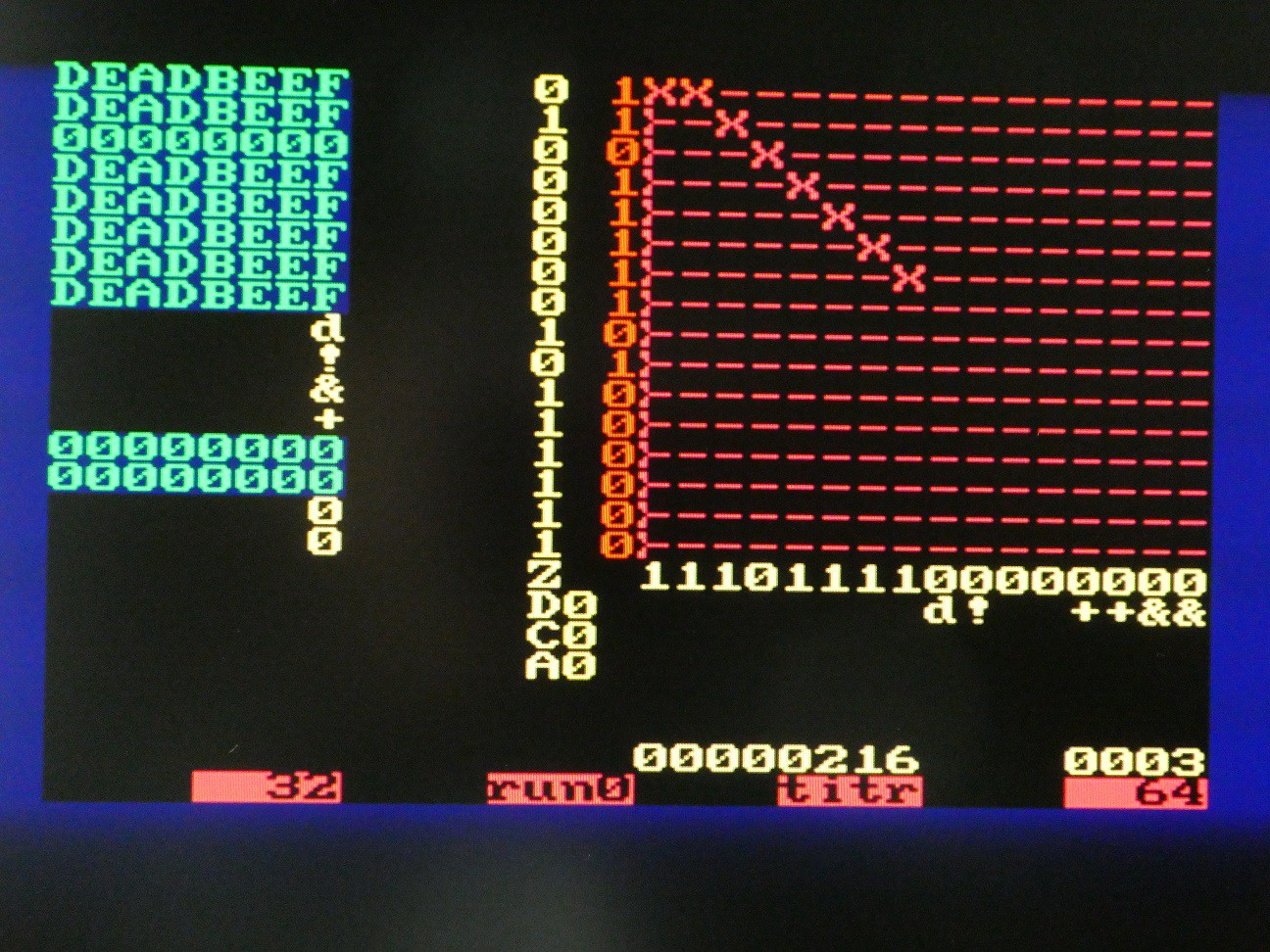
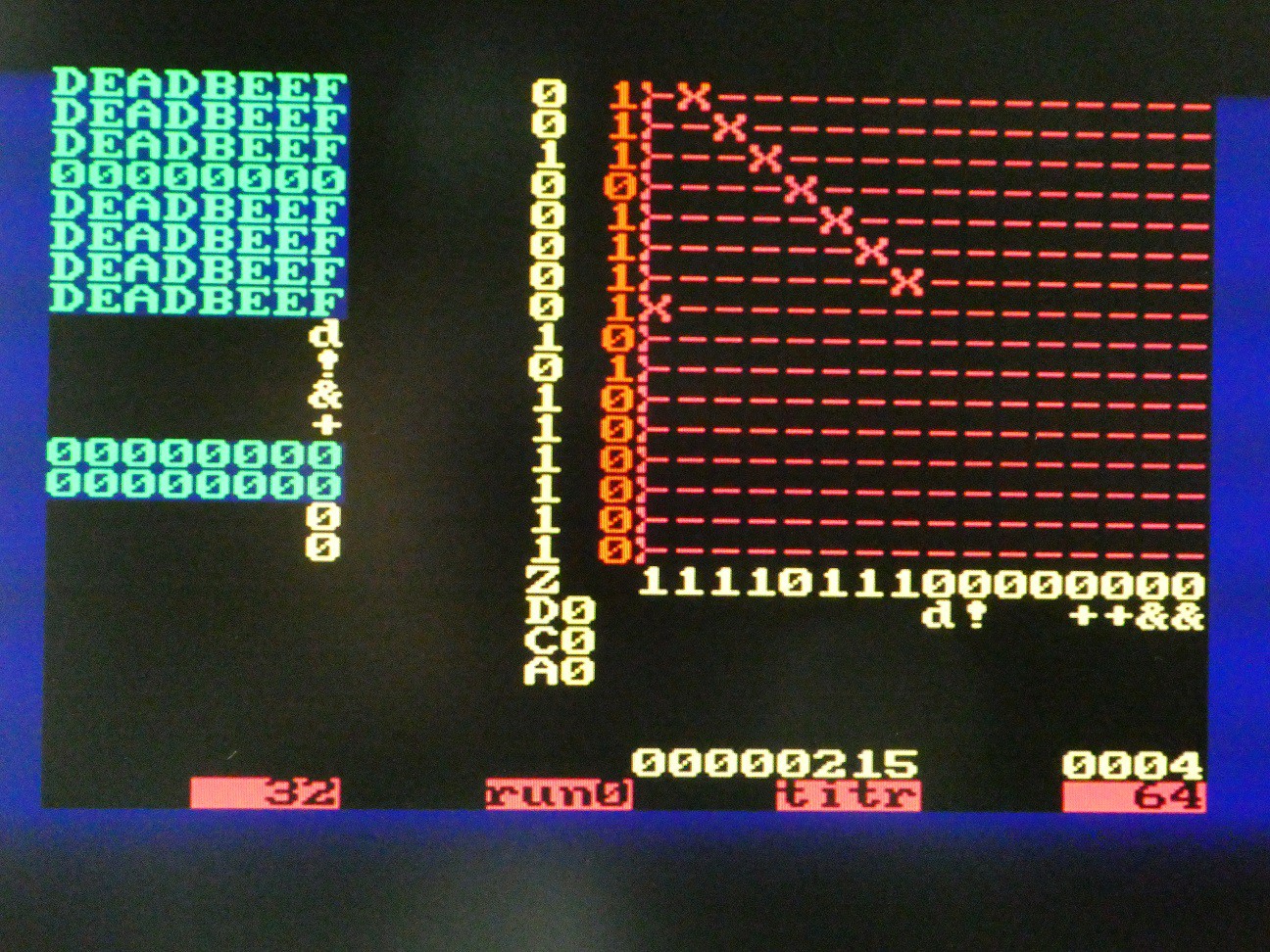
Sample execution of these commands - note "tr" (trace result) option that emits operation ASCII code before, and TOS value after the operation
Discussions
Become a Hackaday.io Member
Create an account to leave a comment. Already have an account? Log In.