 David Tucker
About a year ago I built myself a 3D printed CNC machine. Among other attachments I added a NEJE A40640 LED laser module to it that has a 10 watt optical output. I have been trying to get a handle on how the laser diode works. Recently I have been going over research papers trying to work out the relationship between laser power and cutting speed. I came across a few papers that seem to fit the bill.
if you dig into the papers and do a little simplification you get an equation like this that tells you approximately how deep a cut will be.
This says that increasing the laser power or the number of passes should increase the cut depth in a linear way. While increasing the velocity of the laser head or increasing the size of the laser spot will result in a decrease in cutting depth at a logarithmic rate. This falls out of the math easily enough, if we plug 1 in for all values but power then we end up with depth = x, while if we plug in 1 for all values but velocity we end up with depth=1/x. This equation is missing some constants that dial it in for each material type, so keep in mind this is an approximation.
We can pull out a part of this equation and call it energy per unit length or energy = power/velocity. For any given material type it can only take so much energy before being permanently damaged (burning) and that defines the optimal ratio between power and velocity. Say the material can only take 1 unit of energy before burning, then we can choose to run 1 unit of power at one unit of velocity, or 10 units of power at 10 units of velocity resulting in a faster cut, but we can't get any more depth out of the laser than this. We can try to run more passes to get more depth without adding more energy, but only up to a point.
Another interesting point here is that it is the focus spot size that dictates the ultimate depth of cut. If the spot size grew to 4x its smallest size then we would only have 25% of the energy to cut material. The way the laser focus spot works we end up with a 'waist' where the laser spot size is relatively unchanged, but outside of that area the laser light diverges rapidly. This means that as our cut depth increases past the depth of this waste we start to loose cutting power and eventually it gets to the point where no amount of extra passes, reduction in speed or energy can overcome the loss. Basically any laser, no matter how strong, will ultimately have a maximum depth of cut.
According to these equations there should be no difference between laser power or passes. That is a laser with power of 1 running 2 passes should be equivalent to a laser with a power of 2 running 1 pass. Also there is an inverse relationship between speed and power, so if you want to run at 2x the speed you need 2x the power or 2x the passes to cut the same depth. In practice there are small differences in each material that make power and passes not fully equivalent, and the above limitations are still in place and you can't keep cutting deeper and deeper by just increasing power or reducing speed. But as a rule if someone says they cut at high speed for many passes you can reduce the speed and passes at the same rate and get an equivalent cut
---
Here are some of the papers I used to derive this.
https://www.fpl.fs.fed.us/documnts/fplrp/fplrp250.pdf
http://alumni.media.mit.edu/~yarin/laser/physics.html
https://makezine.com/2019/03/04/a-deep-dive-into-laser-cutter-speed-and-power/
https://www.sciencedirect.com/topics/engineering/laser-power-density
---
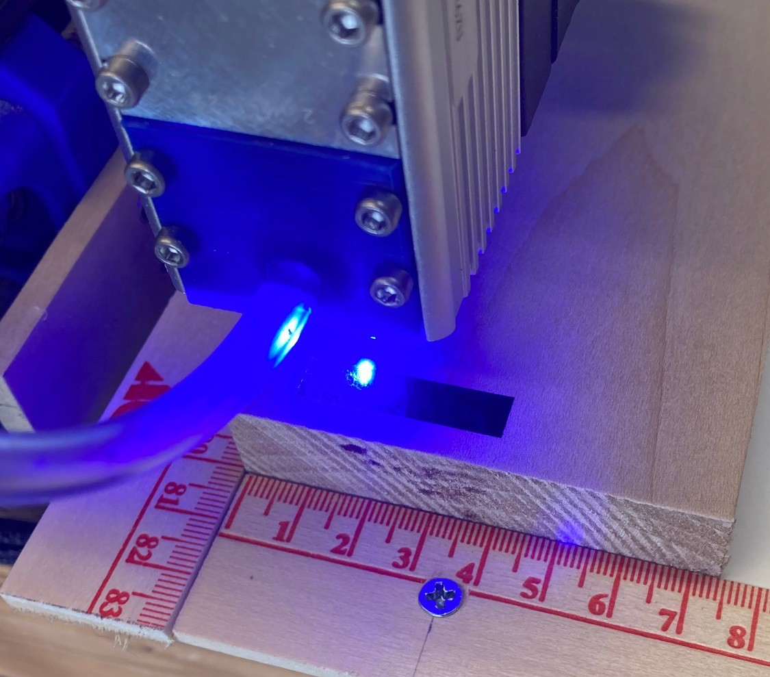
In order to verify the above equation I wrote a test utility that can control my laser. This test is simple, I start the laser just off the edge of my material and run a series of cut lines paralel to the edge of the material. I vary the parameters across the line and then at the end return to start and move 0.2 mm further into the material.
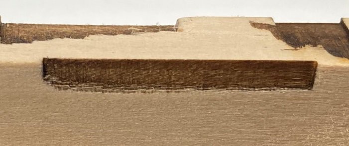
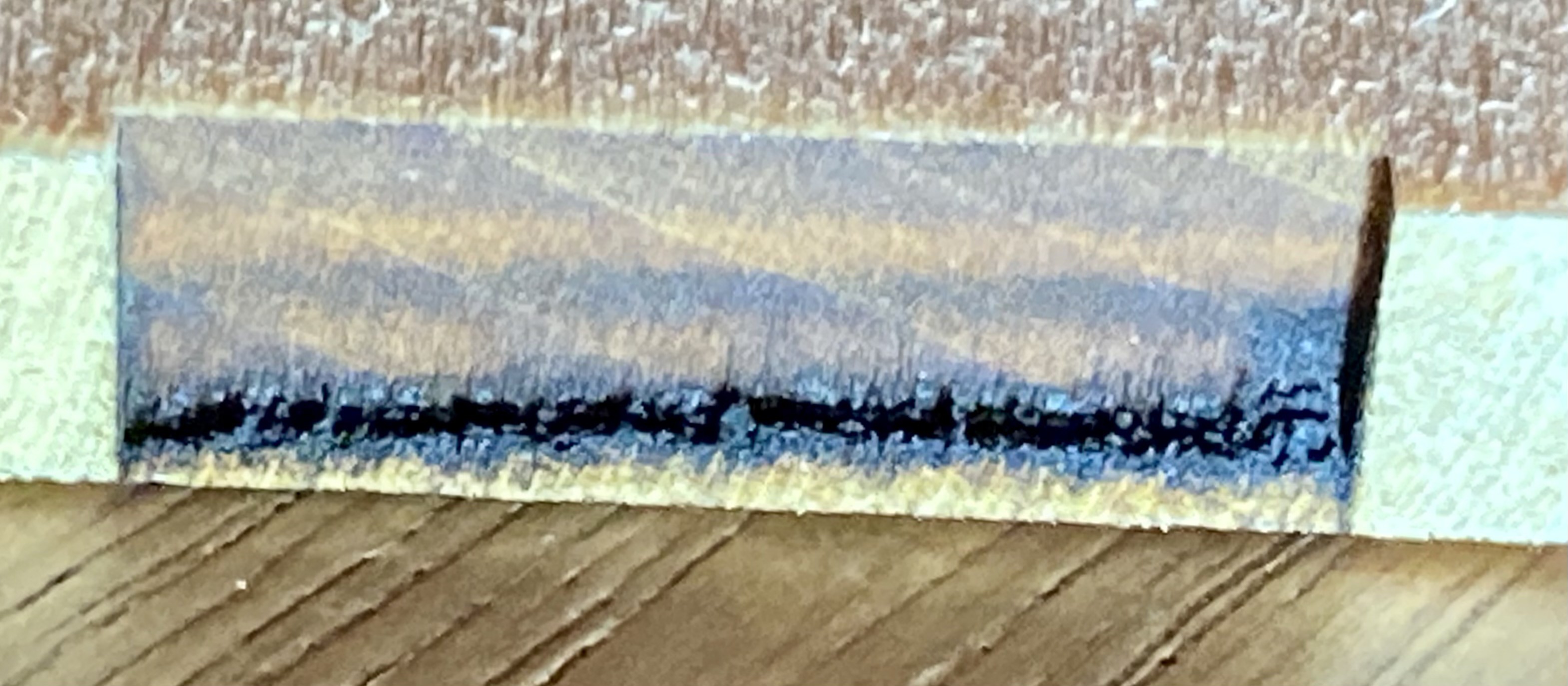 To give you a sense of how that works here is an example of running a simple constant speed and power line over and over again on a piece of balsawood.
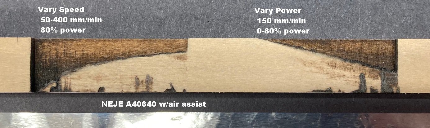
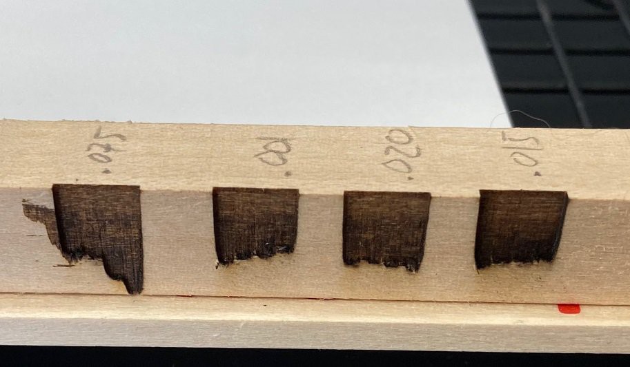
Here are two different tests. The first on the left is linearly increasing speed from 50-400 mm/min with the laser set at 80% power. You can clearly see a logarithmic decrease in cut depth as speed is increased or depth = 1/speed.
The second cut on the right linearly varies laser power between 0%-80% percent with a speed of 150 mm/min. Here you can see that there is a linear relationship between power and cut depth, in other words depth = power. This was done in a 12 mm deep piece of basswood with my NEJE A40640 module.
---
In theory if we hold velocity constant than a cut at a power of 4 and pass of 1 should result in the same depth as a cut with a power of 1 and a pass count of 4, or in other words power = BasePower * passes. To prove this I wrote a program that runs over the same line 4 times, with one segment of the line being cut at full power in one pass, another at 1/2 power in two passes, 1/3 power in 3 passes and 1/4 power in 4 passes. Later I extended this to run 10 passes.
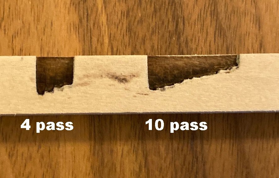
You can see in the images above that there is not quite a 1:1 relationship between depth and power. So to investigate this further I wrote another program that uses the following equation:
power = (BasePower / passes) + (BasePower * 0.02 * (passes - 1))
This works fine for my laser, but it is probably highly dependent on the laser you are using. I have no explanation for this, The laser power is in fact linear so the error is not coming from there. There is a small amount of overlap between passes, it is possible that the spot size grows with power and that is causing the error. In other words this could be a flaw in my test, not a flaw in the formula. Still the correction is small, only 2% * pass count so the relationship while not perfectly linear is close.
---
Another relationship that comes out of this is that of speed vs power. The idea is if you want to hold depth constant then you need to increase power at the same rate as you increase speed, In other words speed = power * factor.
After a bit of experimentation to dial it in I came up with the equation speed (mm/min) = power (%) * 700. Varying power from 0.10 to 0.80 (10% to 80%) at speeds from 70 mm/min to 560 mm/min produced the above cut that shows there is in fact a linear relationship between speed and power over at least most of the range.
---
The only big thing left to investigate is how spot size effects depth of cut. However I don't know that I'm well equipped to study that, or at least I can't think of a good way to measure spot size with enough reliability at this time. Maybe I could try running a ramp test on a piece of anodized aluminum and get reliable measure of spot size from that. However in my past experiments with this, the spot size did not seem to change much over the range I could run the ramp over.
I already tried to write a program that varies the height of the laser head across the pass, however the results were disappointing. If I use air assist it varies in height with the laser head, and if I turn air assist off I get enough damage to the material that it is difficult to read the results. I need to make a new air assist that does not move vertically with the laser head and try this again.
---
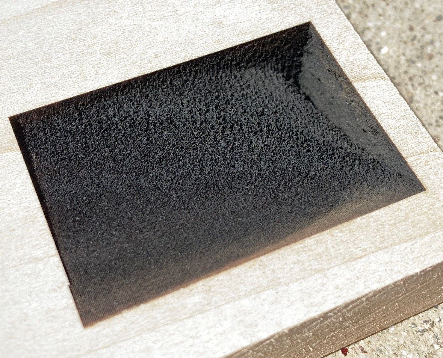
Finally to wrap this all up nicely I wrote a new program that draws a series of lines, spaced 0.2 mm apart while varying power in the x direction between 0% and 80% and speed in the y direction between 50 mm/min and 600 mm/min. I picked up a piece of 20 mm thick basswood to run this experiment on.
After letting this run for a few hours I ended up with this finished cut. It shows the relationship very nicely. However a picture just does not do it justice, it is impossible to really see the detail without holding it in your hands.
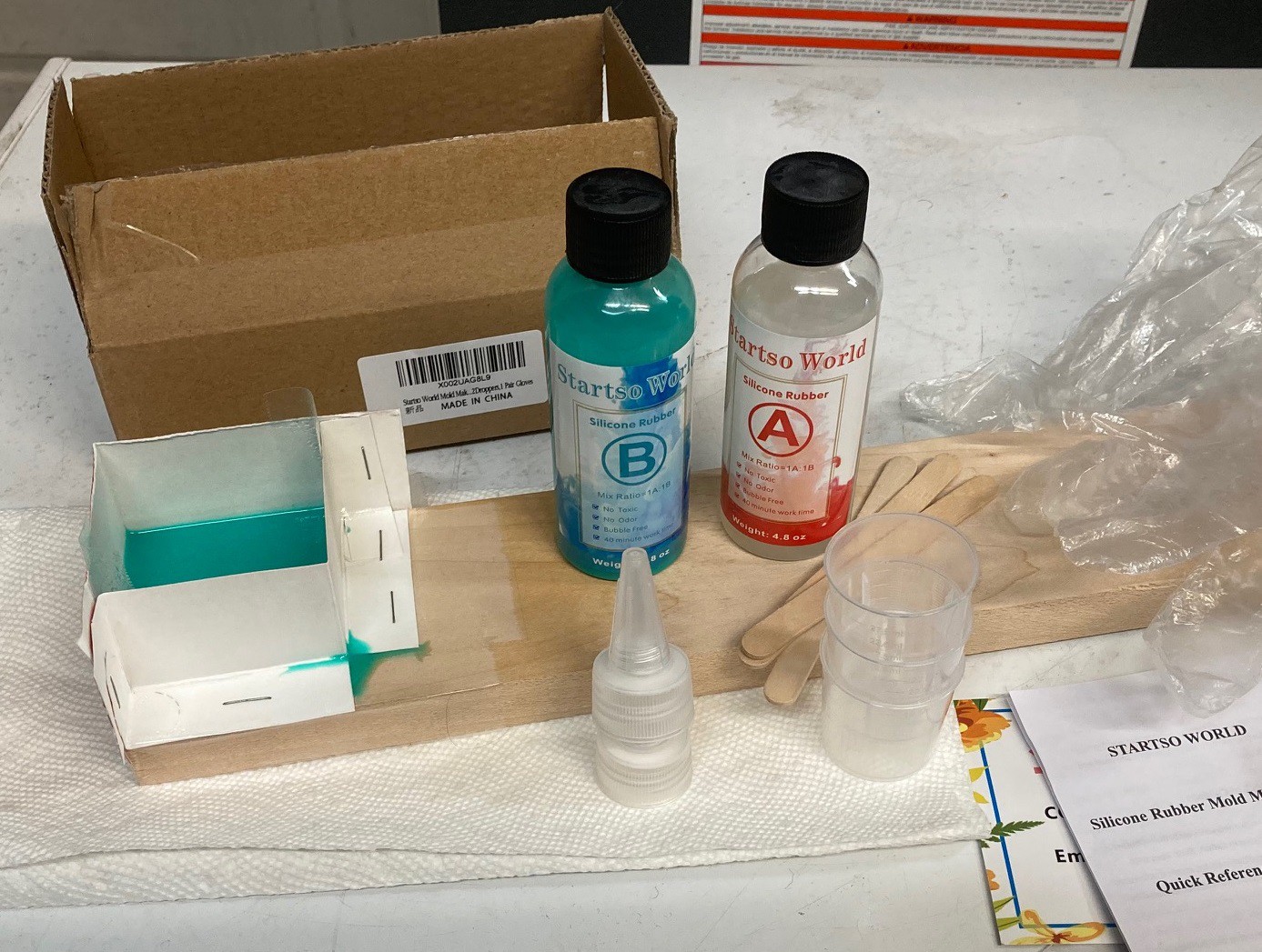
So I hit upon the idea of using a bit of silicon to make a cast of the cut so I could photograph it from several angles. I picked up the cheapest set of silicon I could find on amazon, figuring this would probably fail. However I was pleasantly surprised that it worked well.
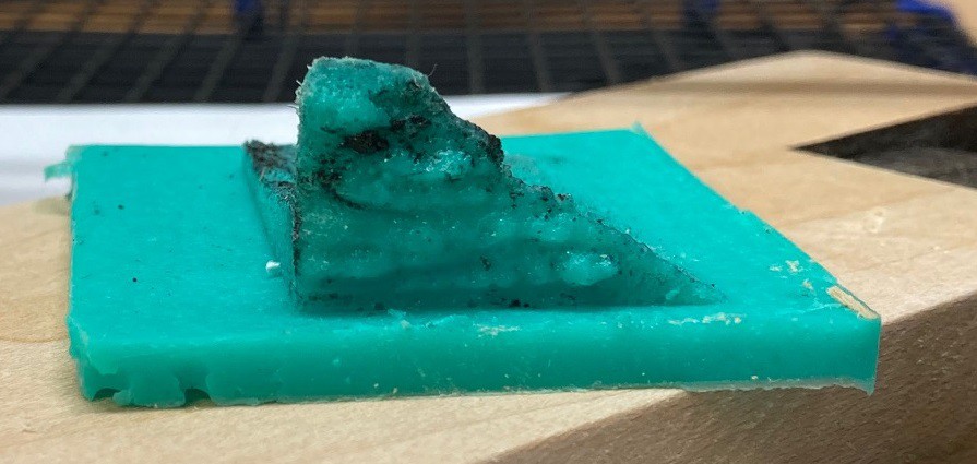
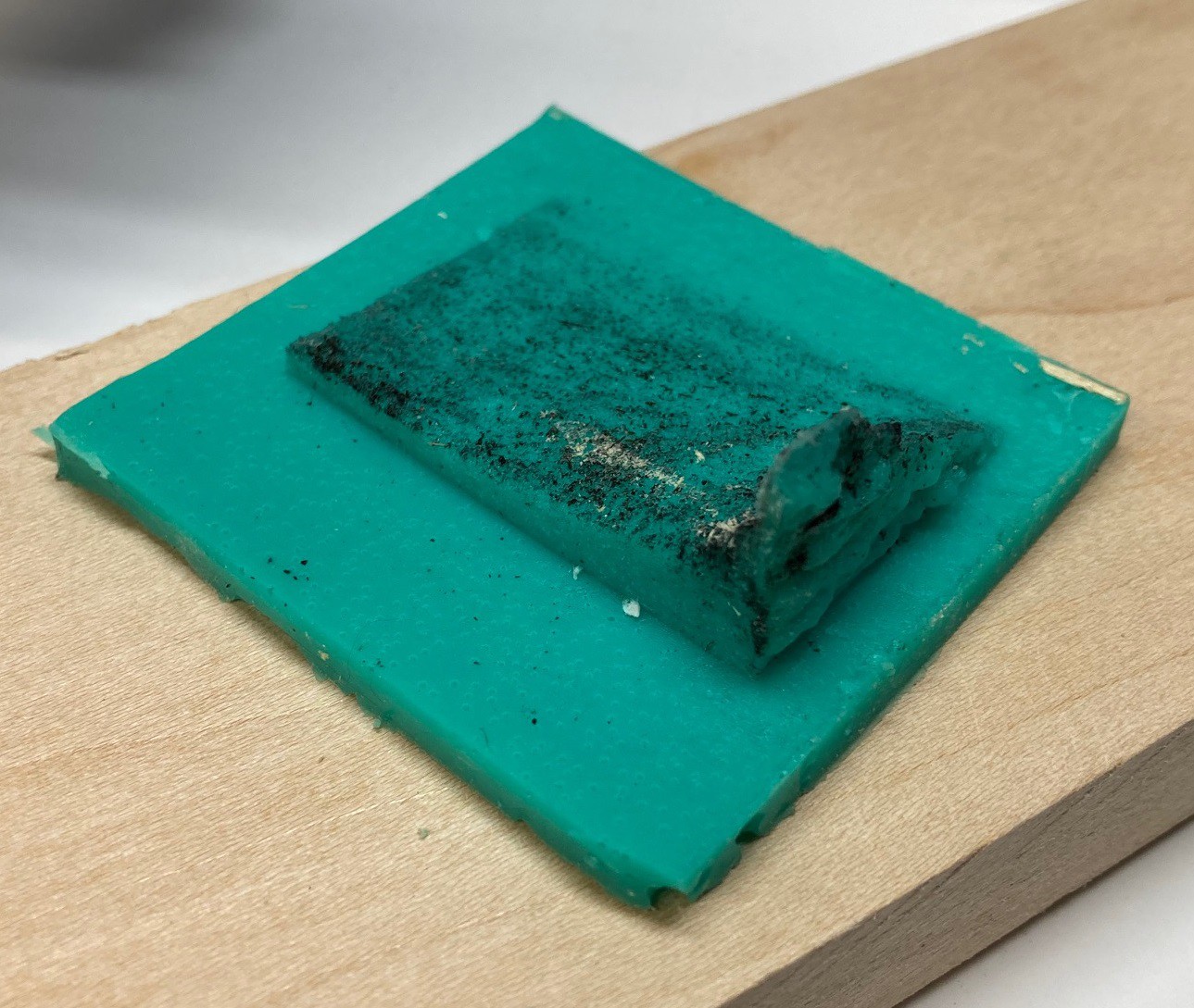
Here is the finished cast, fresh out of the mold. I believe I have captured every part of the cut, no material was left in the mold that I could see. It is crazy how much detail it was able to pick up. The tallest part of the spike is 19mm, this NEJE A40640 laser module can cut 19 mm in one pass, crazy!

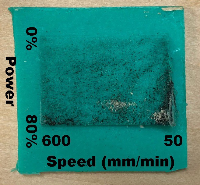
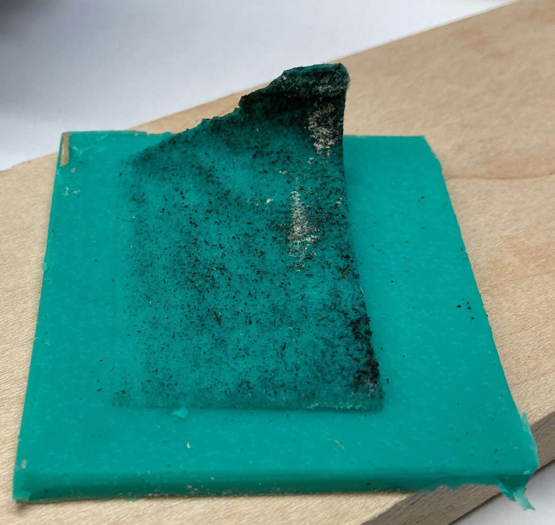
Here is a top down view of the cast. I labeled the variables on the image. The spike is in the lower right corner of the image.
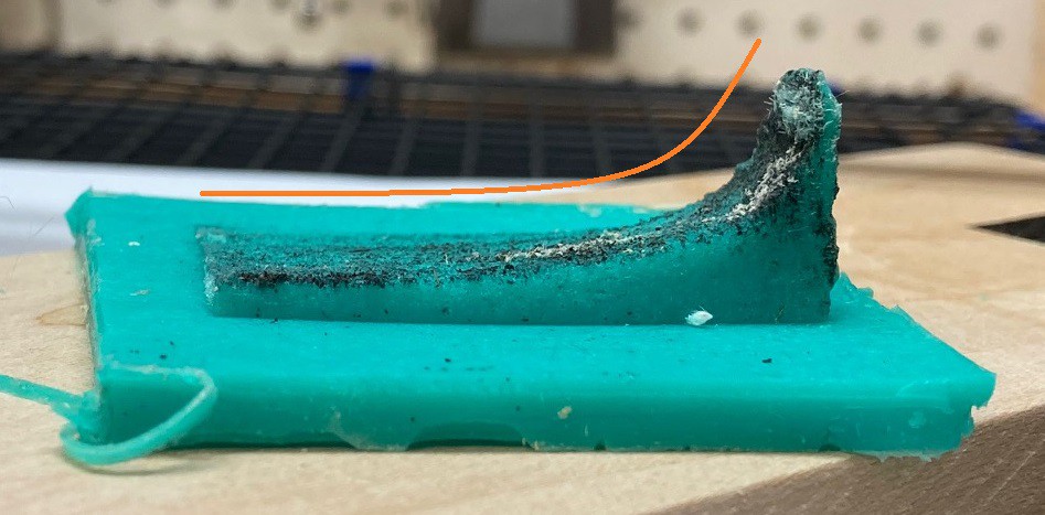
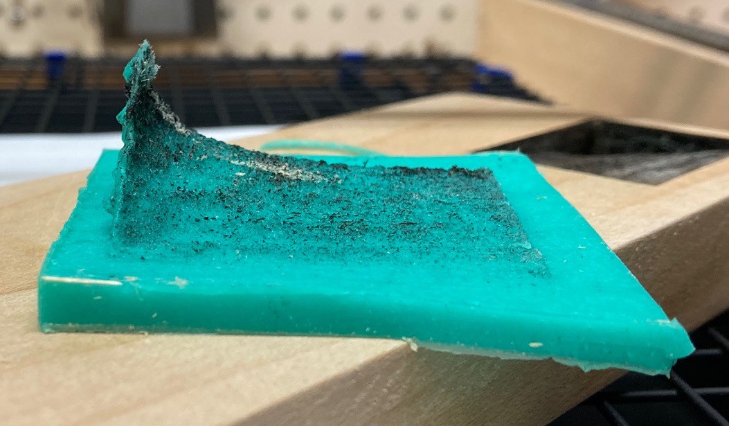
Here is a side shot showing the change in power. You can see that the resulting depth is approximately a straight line. It is a lot more straight at lower depths (faster speeds).
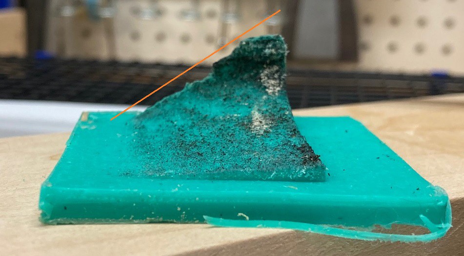
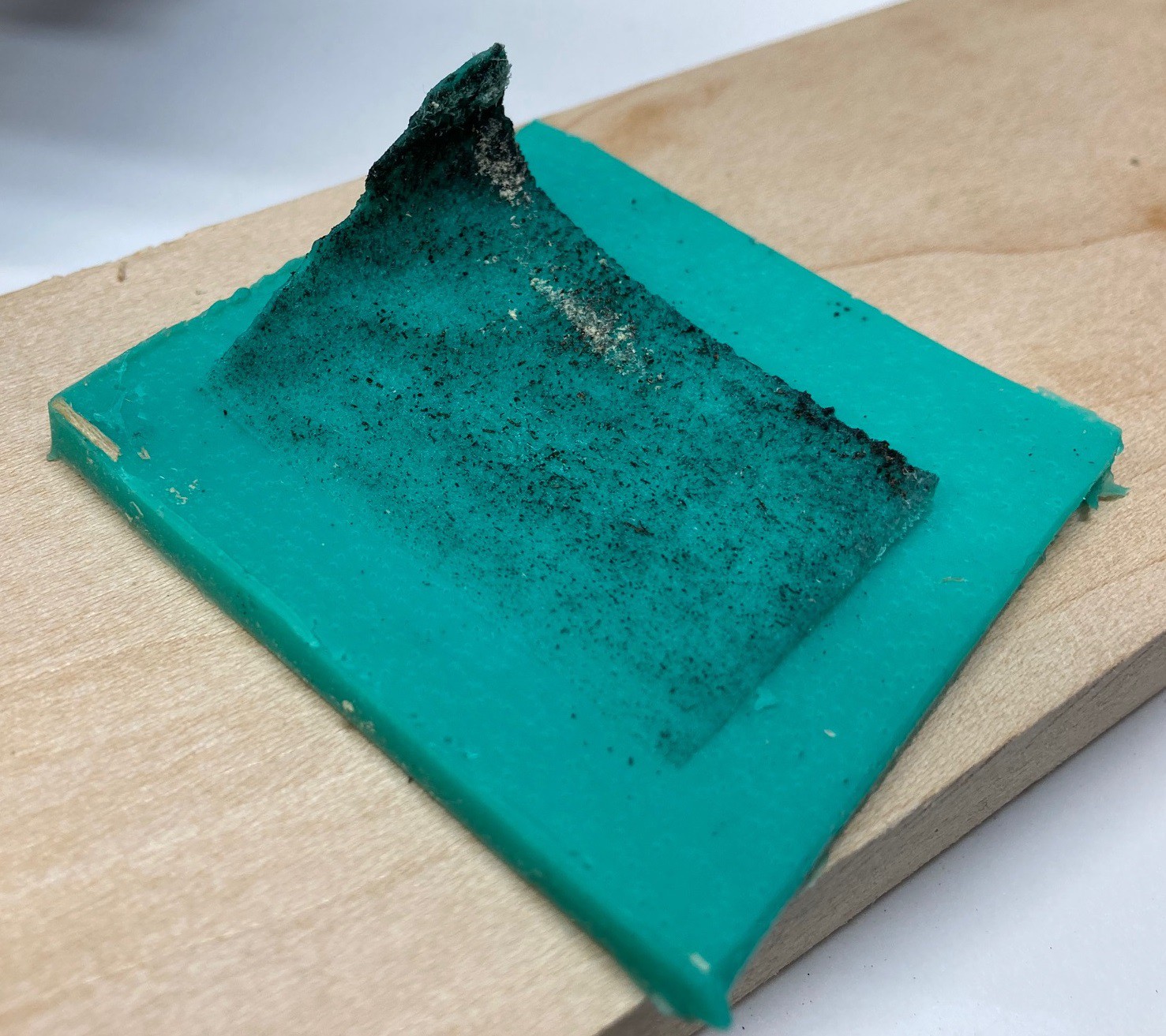
And another side shot showing the change in speed, you can easily see the inverse power (1/x) shape of the cut.
It is interesting to see both in the cut and in the cast that at the highest power at the slowest speed there is a lot of damage done to the material. We see the damage quickly fall off as the speed increases, by 100 mm/min it is looking much better.
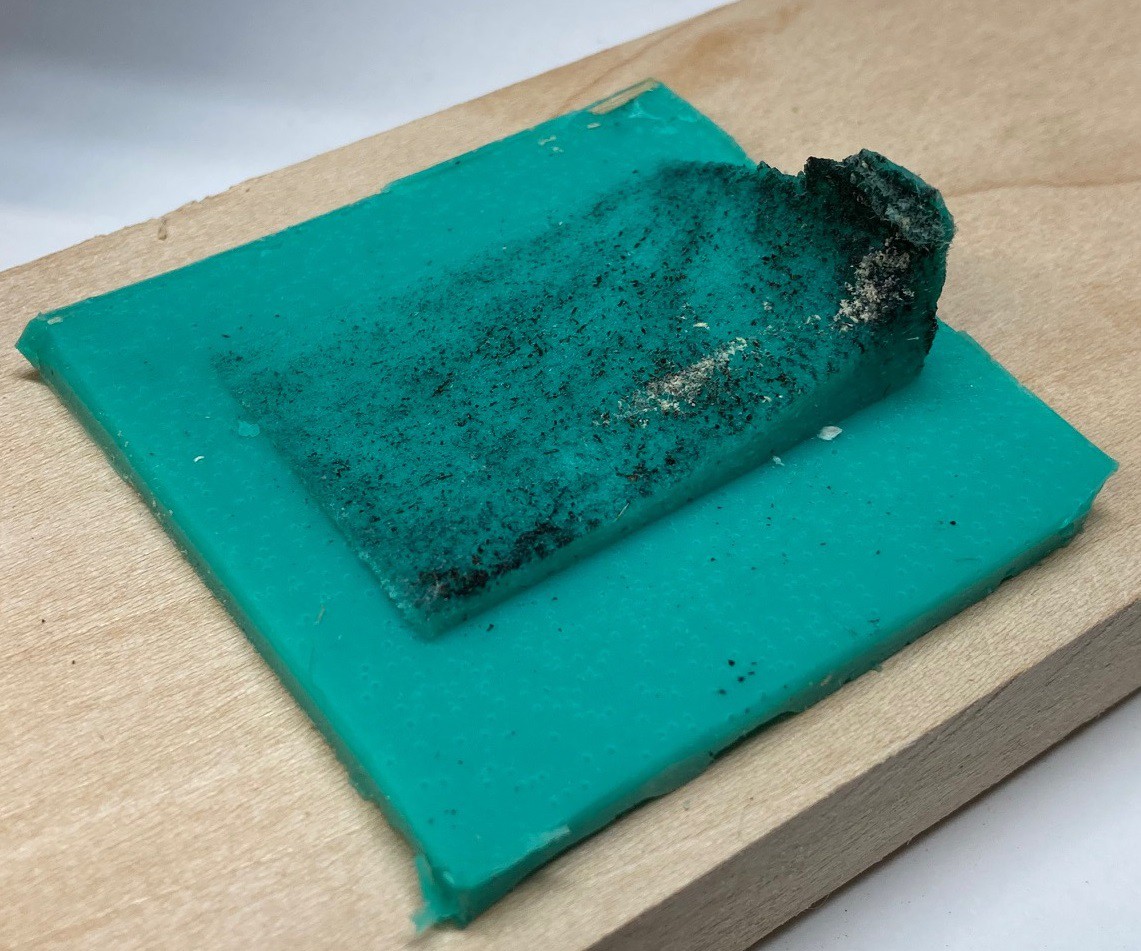
Here are several other shots from different angles.
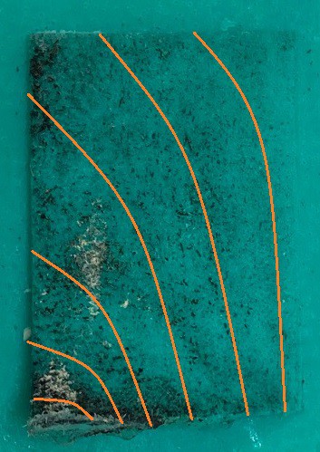
I have not found a good way to mark topographic elevation contour lines on this, but if I did you would see that they are not straight lines but more or less C shaped curves that look something like this.
 ---
---I have two more depth experiments posted below, if you are curious.
https://hackaday.io/project/176110-multibot-cnc-v2/log/204814-stay-focused
https://hackaday.io/project/176110-multibot-cnc-v2/log/205044-try-try-again
---
***Note, the title of this post was stolen from Gareth Loy's excellent Musimathics books. A very good read if you have any interest in music and sound and how math defines the relationship.