My NAVTEX - finder
Sailing along the shore, it is important to get actual weather forecast and nautical informations.
NAVTEX (NAVigational TEXt Messages) distributes important nautical information by radioteletype (RTTY). The frequencies 490kHz (national) and 518kHz (international) are reserved worldwide for this radio services. Each station along the shore transmits its information at the same frequency within a defined time slot of some minutes each four hours, so one can sail along the coast from one country to another and receive local important information without changing the frequency.
In europe, the DWD (german weather forcast) can be received at 147,3kHz with very good weather informations.
Although special receivers for NAVTEX and DWD are quite expensive, these messages can also be received with cheap SSB shortwave receivers. Several programs for decoding the messages are available for PCs and also some APPs for Android devices. So important informations are available at low cost.
The NAVTEX-transmission starts with a short synchronization sequence. Within this time, I have to fine-tune my receiver. As the bandwith is very low (50Hz), the tuning has to be very precise. Often I loose the beginning of the message because
I couldn't finish tuning fast enough and I have to wait four hours until the next transmission starts.
So I did like to build a precise and portable test-transmitter, that enables me to tune the receiver some time before the message starts. This transmitter should generate the relevant frequencies 147,3kHz, 490kHz and 518kHz.
Generation of frequencies with a microcontroller is easy as long as the ratio between clock and target frequency is a whole number, or if the frequency divider is large enough, that an imprecise divider doesnt matter.
So the main challenge of this project was the precise generation of odd but high frequencies, where the ratio between clock and target frequency is a small fractional number.
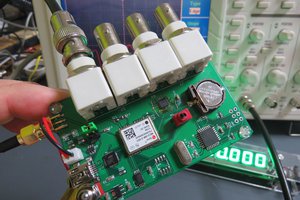
For this project I choose a microcontroller ATMega32. From view of hardware, this controller is oversized, because only one active portpin is needed. Even the smallest ATTiny should do this job.
Precise frequency generation
The clock of my CPU is generated by a standard 16MHz crystal. The generation of a frequency of 147.3kHz (DWD) with a timer needs a frequency divisor of
Programming the Timer with a divisor of 108 will generate a frequency of 148.15kHz, a divisor of 109 gives 146.79kHz. The frequency resolution is about 1.3kHz. The frequency error of both divisors is more than 500Hz, this is too large for my application.
The solution is to alternate both divisors (108 and 109) in the correct way.
The following calculation is done regarding the cycle period. For each divisor, the error of the resulting cycle time is precalculated. N=108 generates a period, that is 38.9ns too short, N=109 results in 23.6ns too long.
My program generates an interrupt each cycle, where the error of the actual divisor is integrated. This can be interpreted as a kind of phase error. If the phase error is positive, the cycle time has to be reduced so N=108 is used for the next cycle, else the error is negative and N=109 is used. This algorithm assures a limited phase error and generates the target frequency with high precision. This algorithm is a variation of the Bresenham- or DDS algorithms.
The runtime of the interrupt routine was optimized, so the error is precalculated in integer arithmetics, and the deviation of the perfect N to the choosen devisor times 128 is integrated in a char variable. This gives an improved frequency resolution of less than 10Hz. This is approx. the tolerance of the crystal and can be accepted.
With all further optimization the runtime of the interrupt routine was minimized and frequencies up to 190kHz can be generated. This is suitable for DWD, but not for the NAVTEX frequencies. But as the CPU-port generates square waves, the NAVTEX frequencies can be generated with the third harmonics,...
Read more »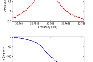
 Dan Berard
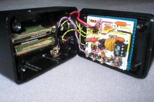
 Scott
Scott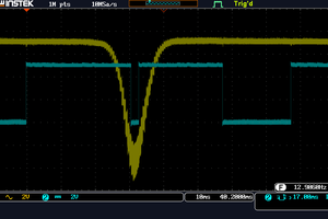
 kodera2t
FYI, newer mid range PICs (PIC16F1XXX) have a 20bit dds accumulator in them (square not sine), so you can do this to much higher frequencies in hardware.