-
First tests and assembled turbine wheel
05/31/2022 at 17:27 • 0 commentsIn the last few days I have tested the assembled spear valve. Unfortunately I don't have any videos of it (yet).
However, the test was only partially successful.
The valve itself worked well and the water jet came out of the nozzle well focused.
Unfortunately, the connections between the individual elements were not waterproof.
That's why I'm currently testing a new connection method in which I swapped the ring seals for flat seals (printed from TPU). So far I haven't got around to test this seal. I will let you know as soon as I have any results here.That being said, I assembled the turbine wheel. You can see a short video about ithe result here:
-
First prints and assemblies
05/20/2022 at 17:11 • 0 commentsHere comes just a small update about the current state. :)
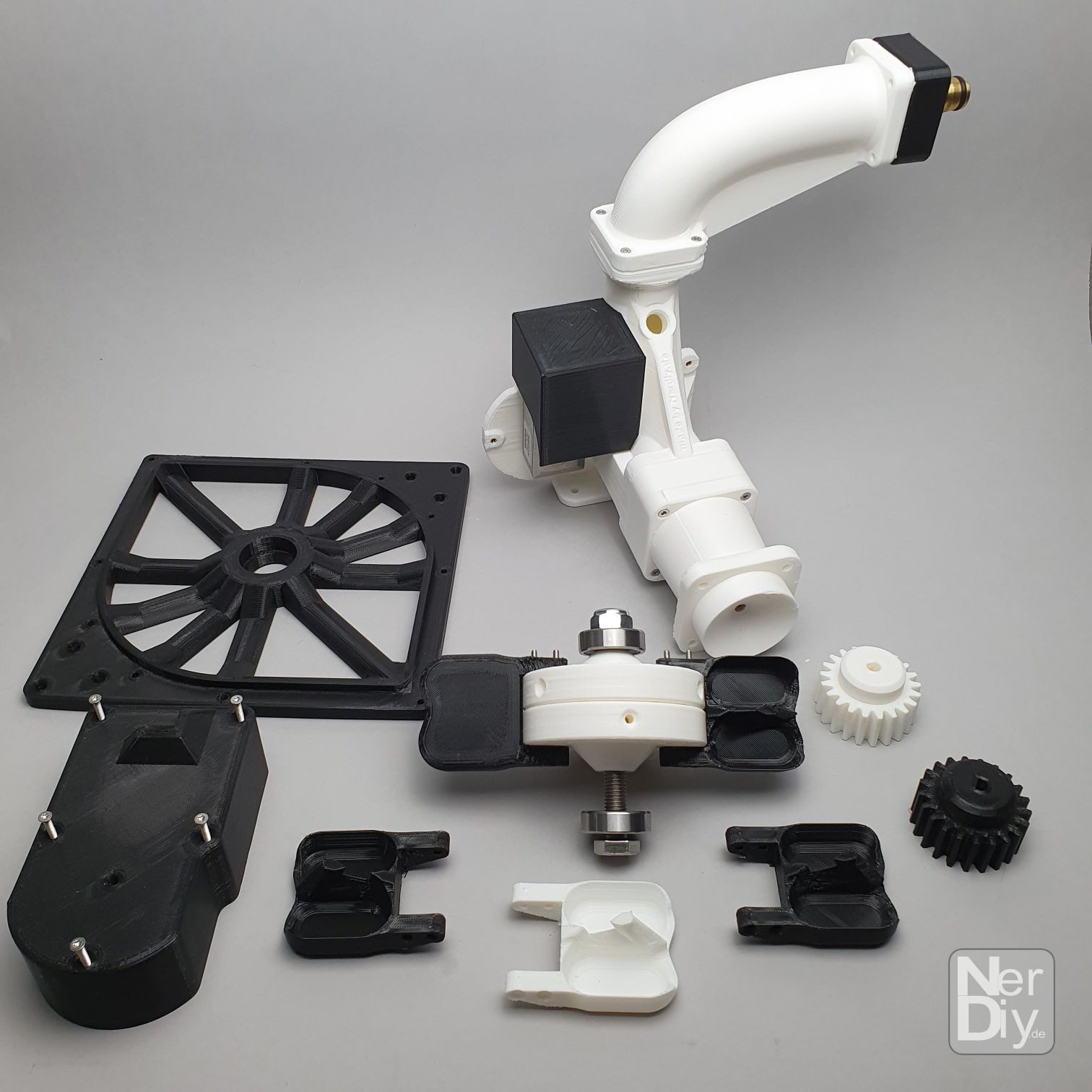
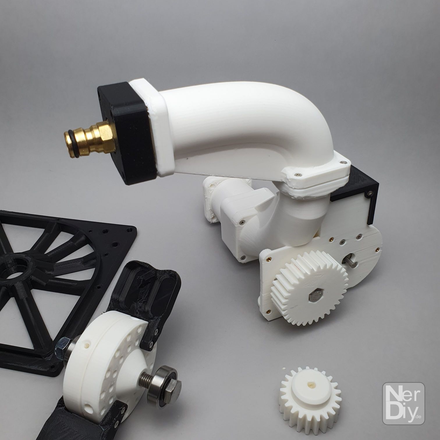
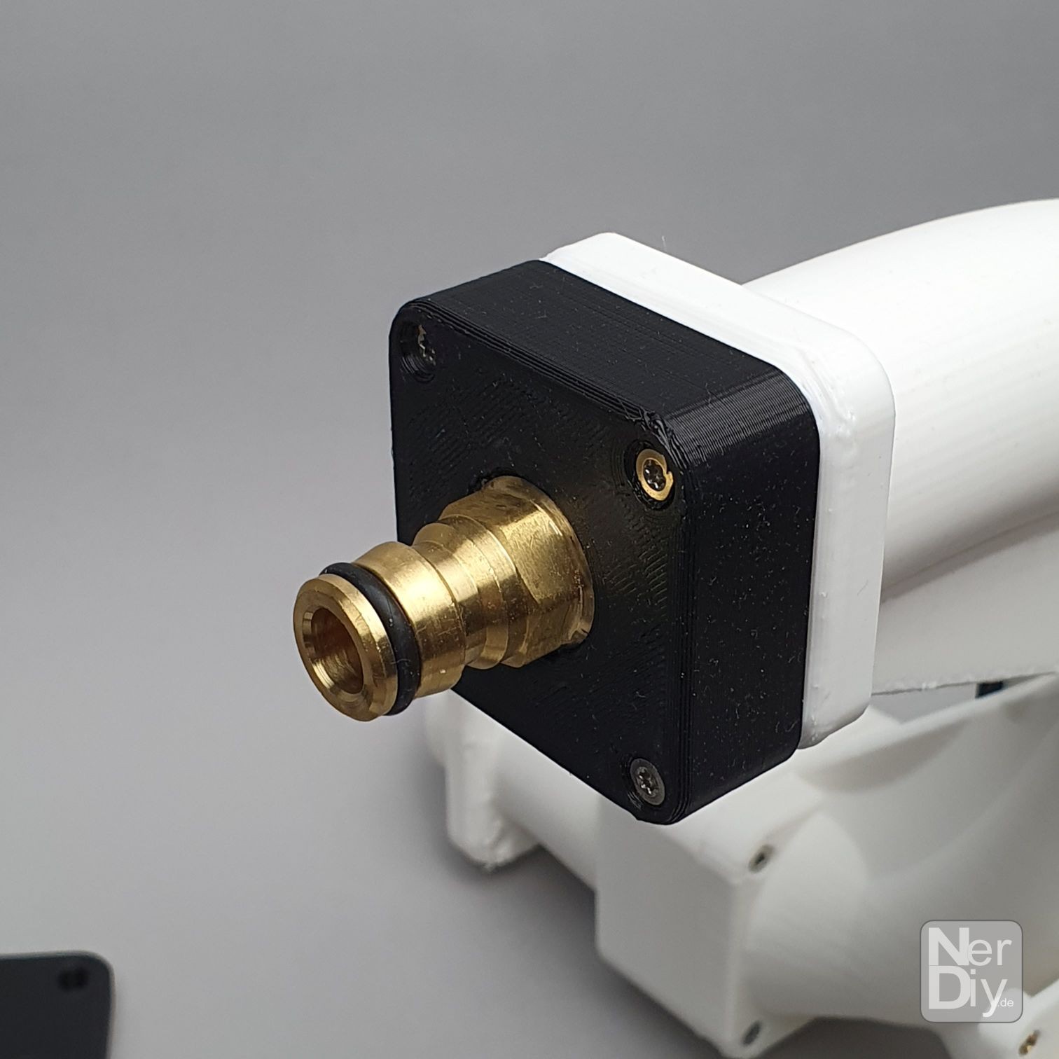
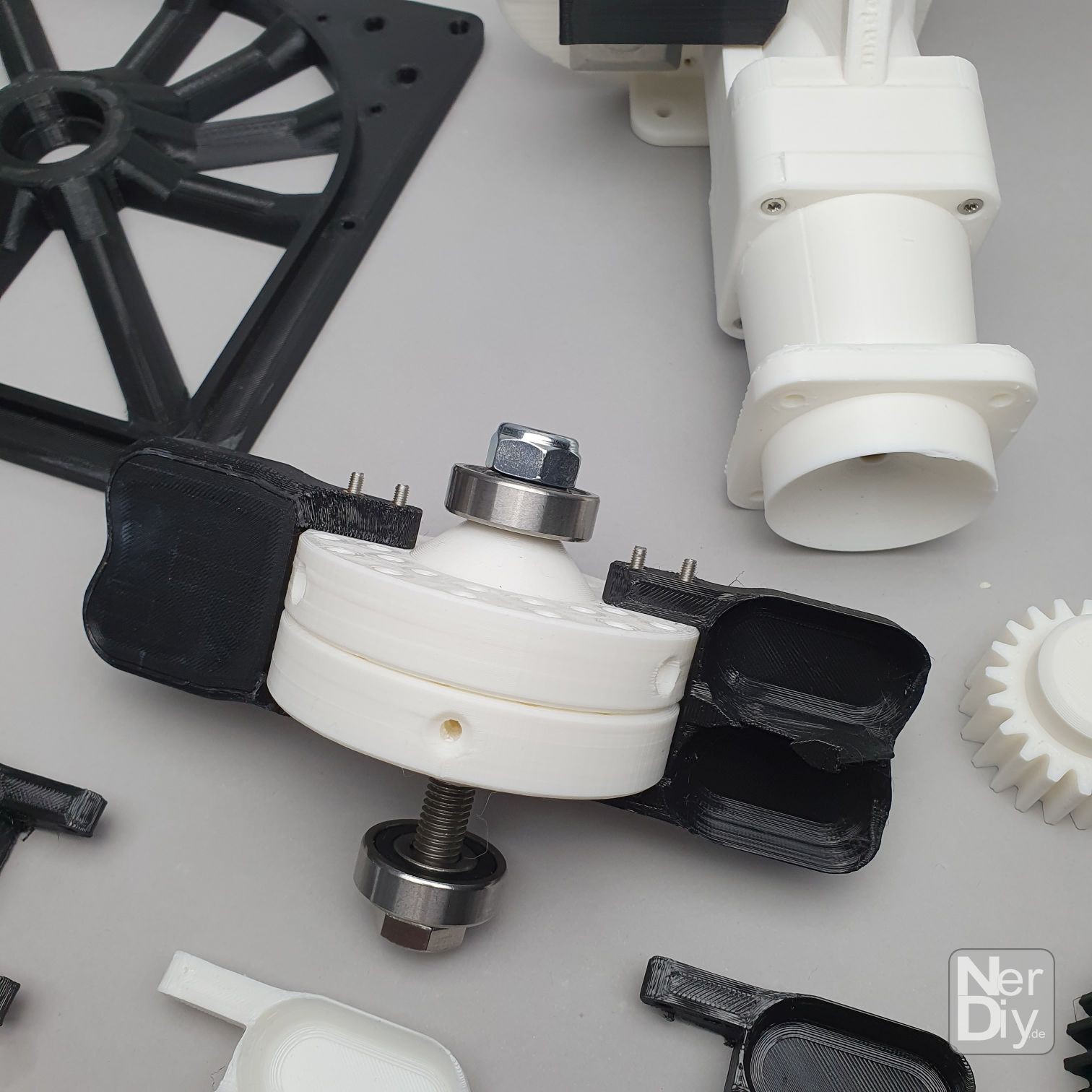
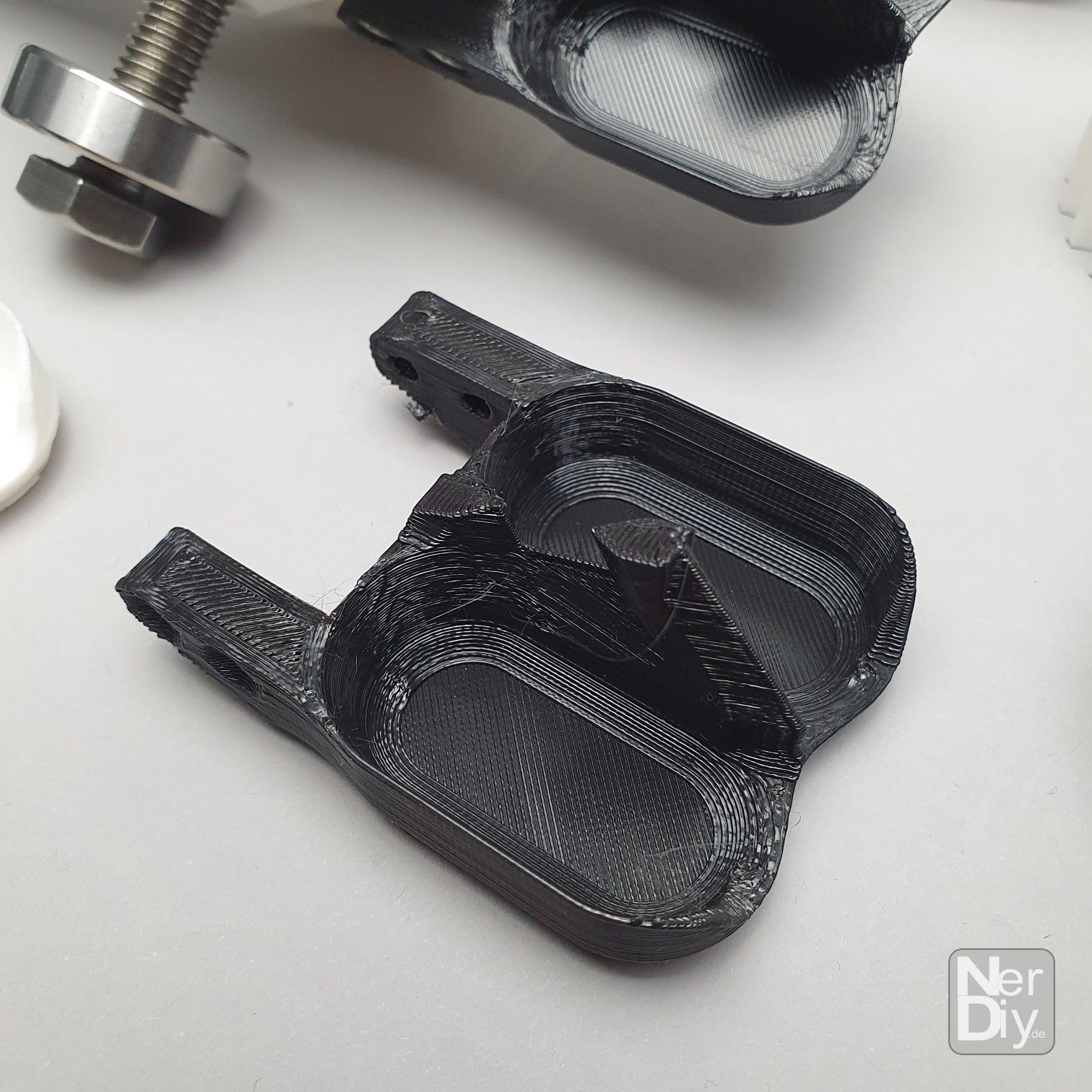
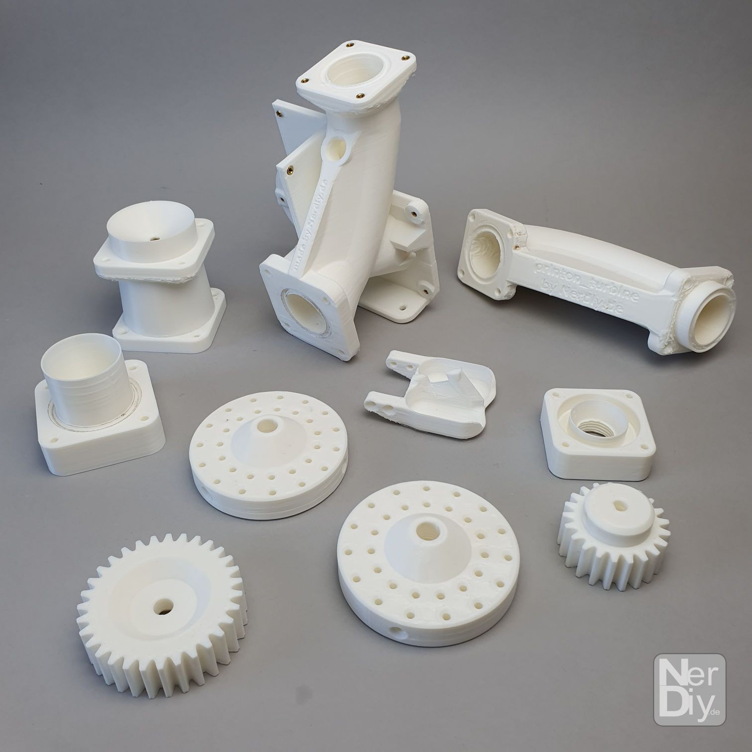
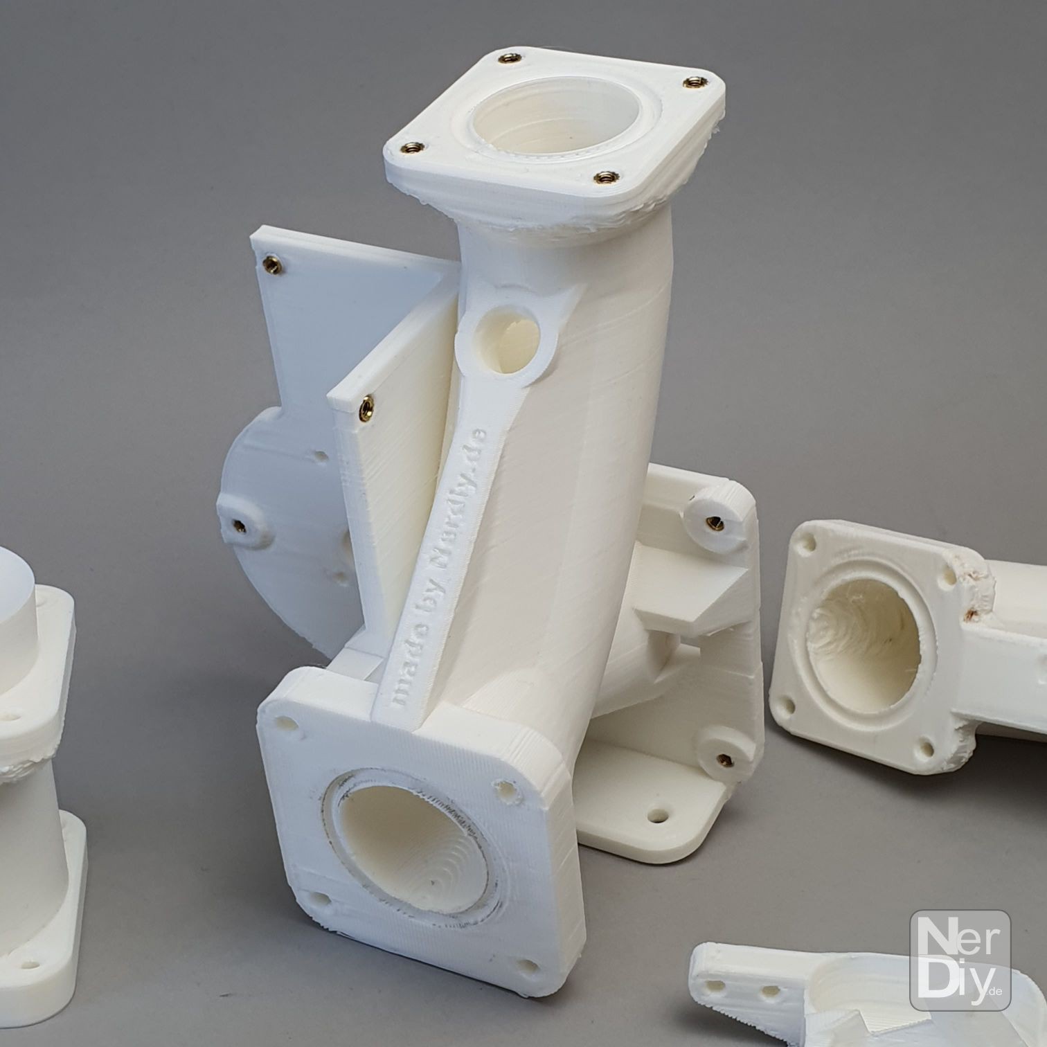
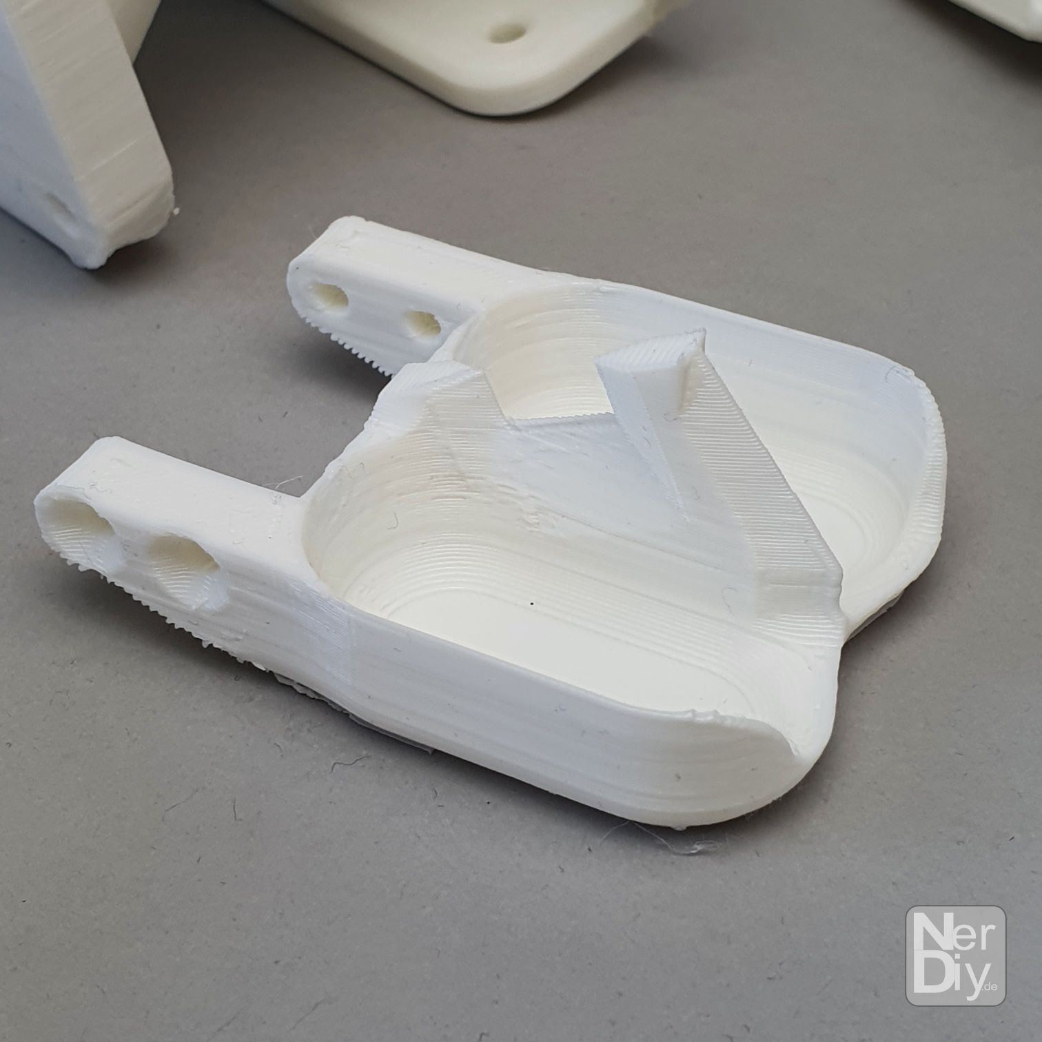
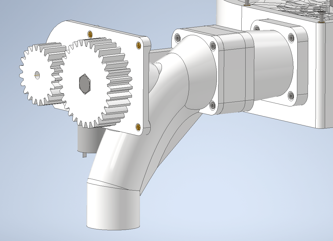
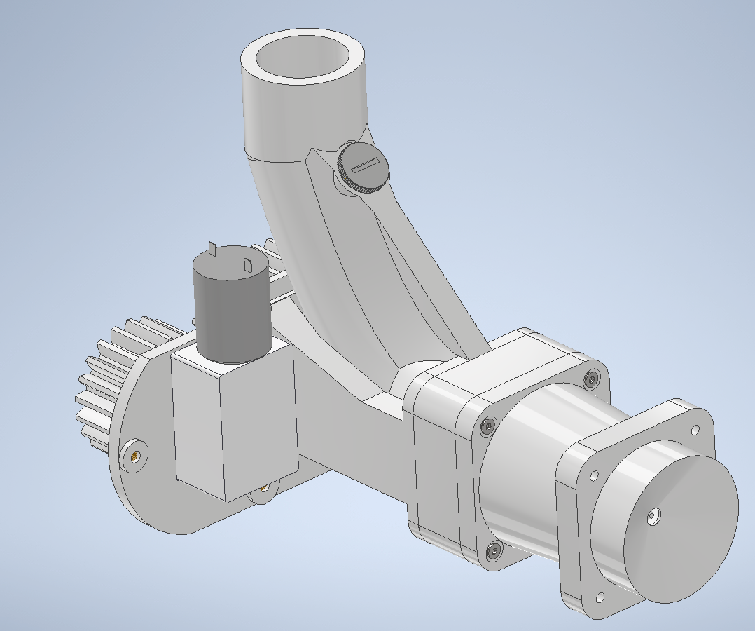
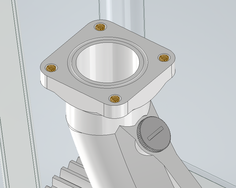
I printed most of the first parts and also assmbled the first version of the spear valve. I want to make some test with it first before I start to integrate it into the housing.
![]()
![]()
![]()
![]()
![]()
-
Let's decentralize production of decentralized energy production
04/30/2022 at 19:37 • 0 commentsIn a small blog post in the WinDIY_2 project I described why I believe that a concept like WinDIY or the printon_turbine is needed to face current energy problems.
You can find it here: https://hackaday.io/project/184849-windiy2-horizontal-axis-wind-turbine/log/205658-lets-decentralize-production-of-decentralized-energy-production
-
Printed printon prints
04/28/2022 at 16:32 • 0 commentsI am currently waiting for the ordered components. So I can use the time perfectly to start and test the first 3D prints.
I am particularly curious if the seals between the 3D printed components are sufficient.
I would also like to check how well the flow can be regulated with the spear valve.
Here are a few photos of the currently printed parts. :)![]()
![]()
This print took 18 hours. :D ![]()
One of the 3D printed buckets. I hope that this will withstand the water pressure. -
Housing and some more interior
04/26/2022 at 17:37 • 1 commentIn the last few days I have worked out some of the planned details.
Spear valve:
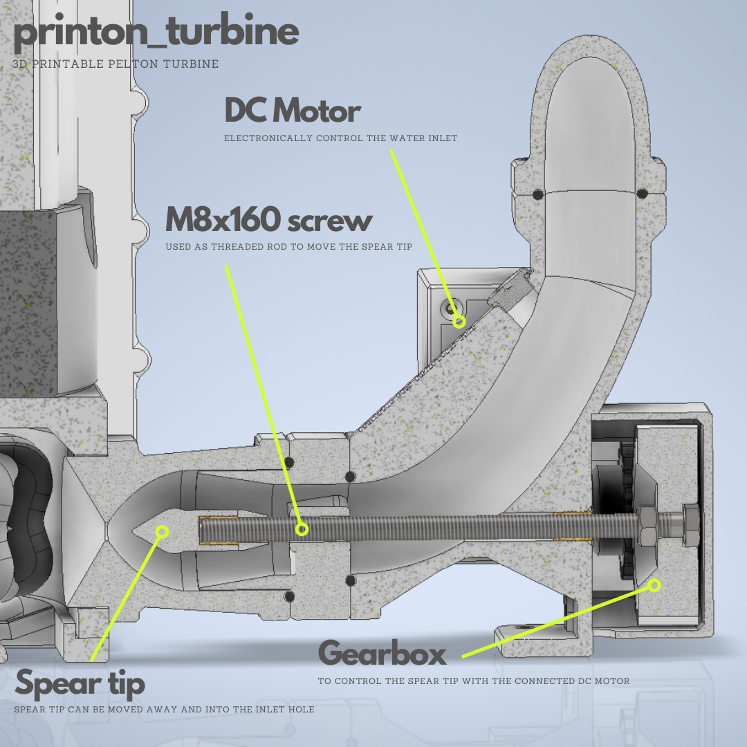
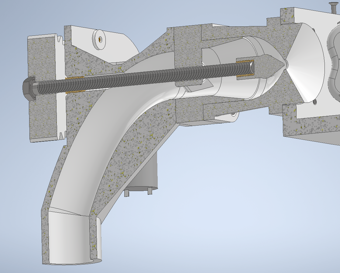
The spear valve is now equipped with suitable seals/recesses for it. I have currently planned with existing standard sealing rings. Later I would like to try to replace these with 3D printed TPU filament seals.I have attached a cover for the gear and the DC motor so that they are at least splash-proof.
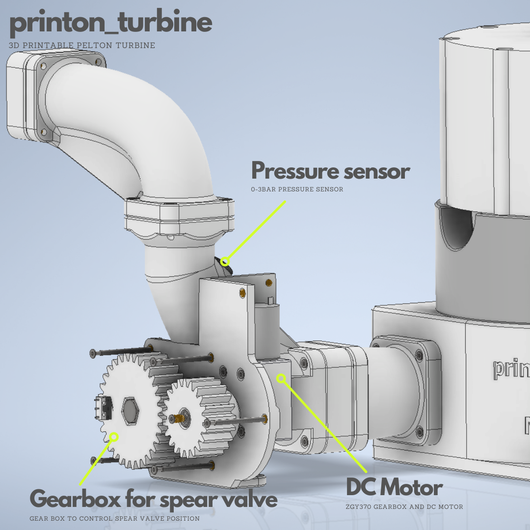
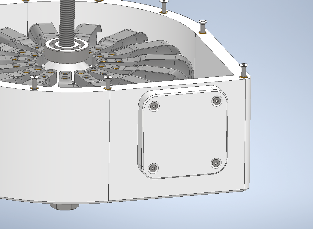
The cover of the gearbox also got a drain, because I'm still unsure how much water loss occurs through the M8 thread of the push rod. Any escaping water should then flow down out of the gear box.Additionally I installed two end switches for the maximum positions of the spear valve. This way it should be possible to recognize both positions. The intermediate positions can then be approached over the running time of the DC motor. Actually, I would like to have more precise feedback on the valve position here, but for now I have only noted this point on my nice-to-have-to-do list. :)
![]()
Cross section of the spear valve. You can also see the rubber seals in this view. ![]()
Gearbox and dc motor without caps. Generator:
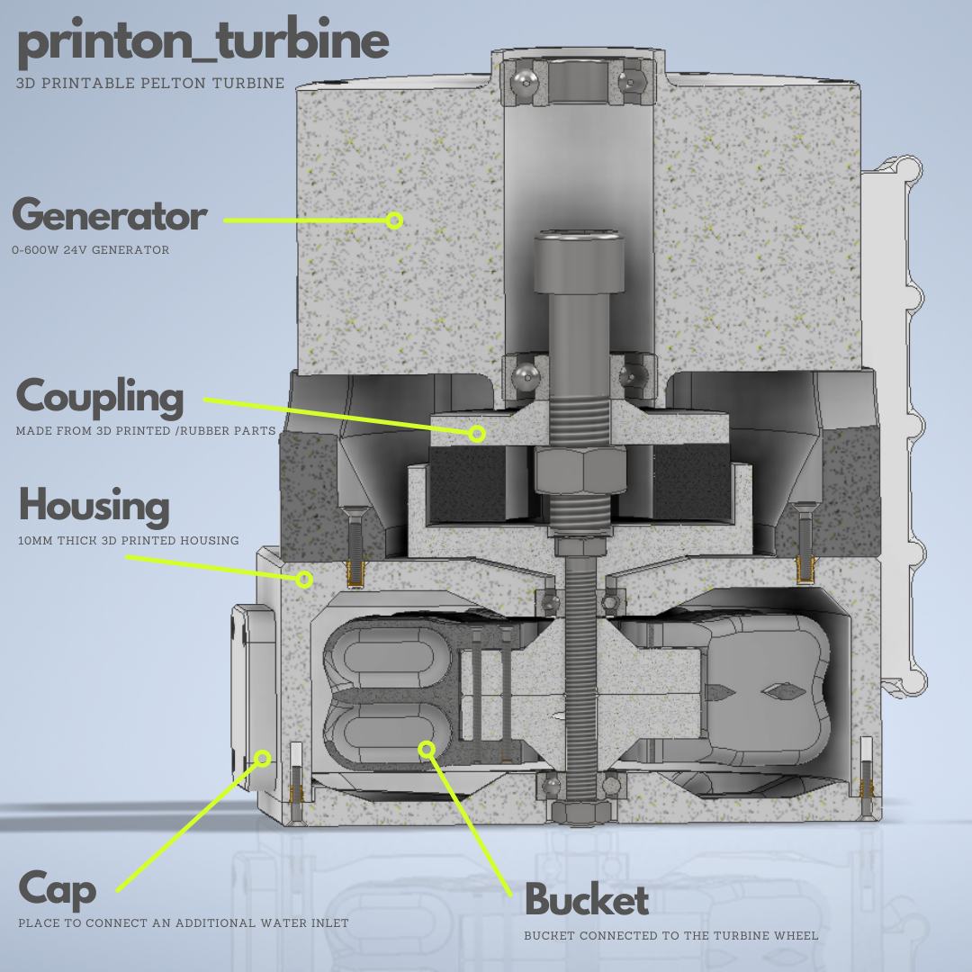
I created a CAD dummy for the ordered 24V generator in order to be able to plan at least roughly (unfortunately the data sheets for this generator are a bit sparse when it comes to exact dimensions).
So I was also able to create a first draft for a coupling from the generator to the turbine axis. For this I have created two clutch discs that interlock with rubber buffers. (I'll make a separate log to explain it better. :))![]()
Cross section of the turbine, generator and coupling. Charge controller and electronics box:
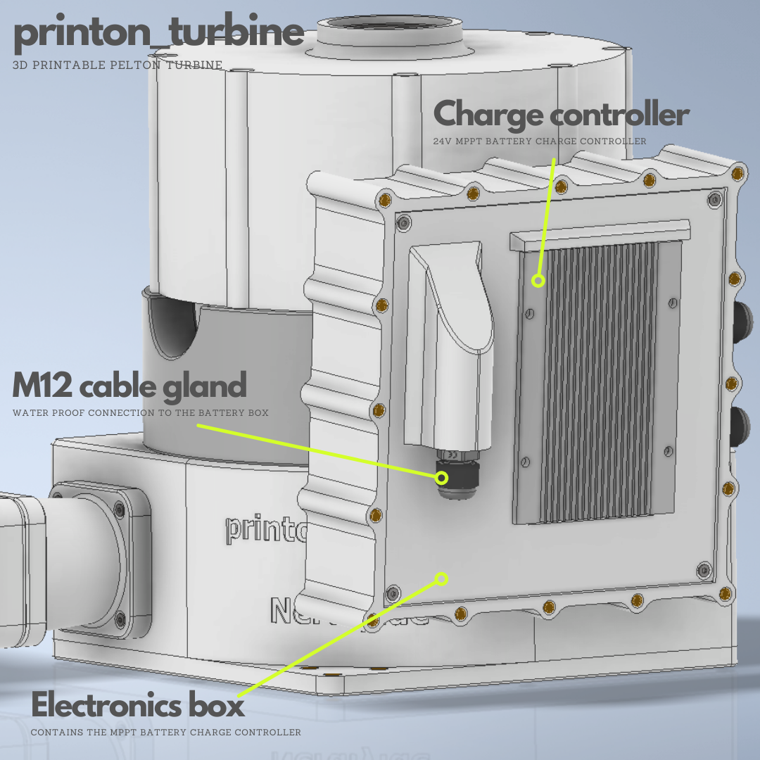
In addition to the generator CAD dummy, I also created a suitable dummy for the charge controller. This is housed in a separate waterproof housing. The controller is mounted in the housing in such a way that any heat generated is dissipated to the outside.
An M12 cable gland is also integrated into the cover of this housing. The connection cable to the battery box can be fed through here.![]()
![]()
Current system overview ToDo:
My next todo is mostly about the other planned boxes. I plan to have one additional box for the water inlet incl. filter system. From this box the pressure line will be connected to the turbine box.
Additionally I plan to create another box for a small buffer battery. I'm still undecided on how exactly this should look like.In principle I would like to have a complete system accommodated in two to three 45L Ikea Samla boxes. The system can then be assembled and commissioned on site. At least thats the plan. :)
-
Current state
04/19/2022 at 16:27 • 0 commentsIn the last few days I've been thinking about the structure of the printon_turbine and the system around it.
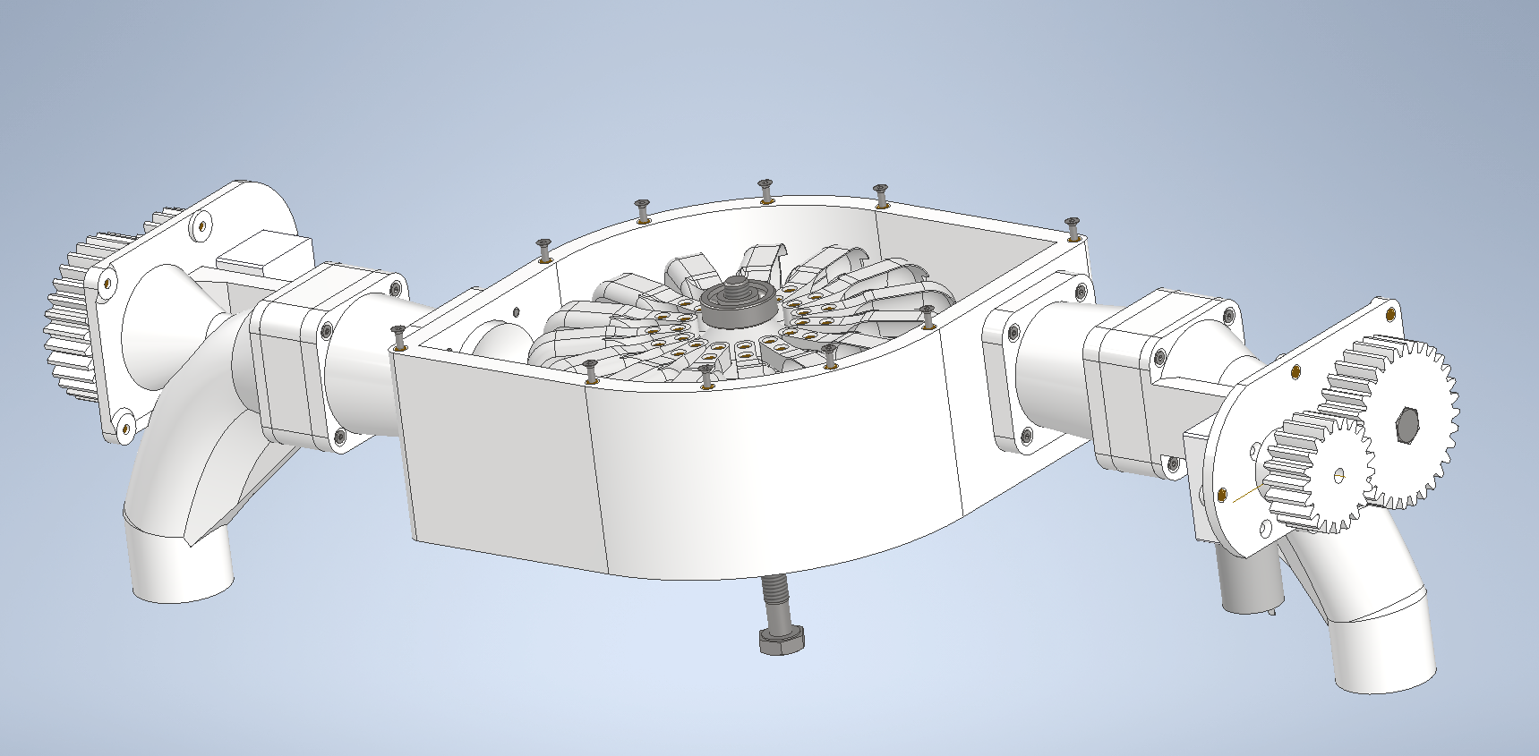
I have made the following changes and additions.- The housing has been processed in such a way that it is possible to equip two sides with spear valves. In this way, the buckets of the turbine can be driven from two opposite sides. This is only optional, which is why I also designed a suitable plug in case you want to use one inlet only.
![]()
printon_turbine incl. two mounted spear valves ![]()
![]()
- I started with the missing details for the spear valve. The size of the water jet should later be adjustable via a small DC motor. I have integrated a suitable reduction gear and DC gear motor into the design.
![]()
![]()
![]()
- I have also added a mounting option for a pressure sensor (https://de.aliexpress.com/item/1005004132586500.html) to the spear valve. In this way, the water pressure in the supply line can also be monitored electronically. This sensor is integrated in a G1/4 thread. If not required, the opening can simply be closed with a corresponding plug.
![]()
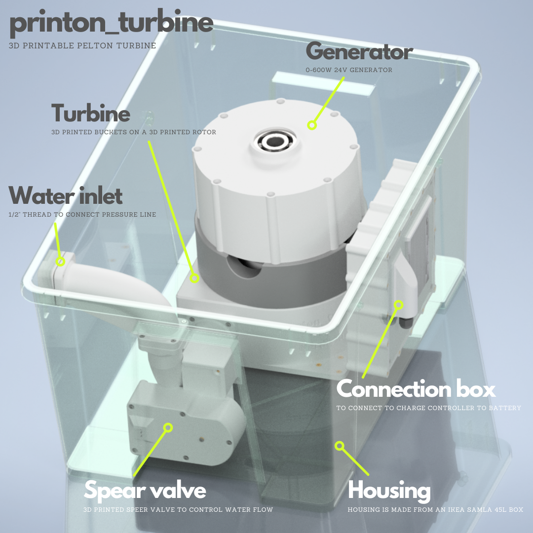
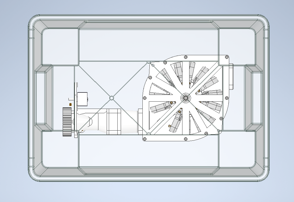
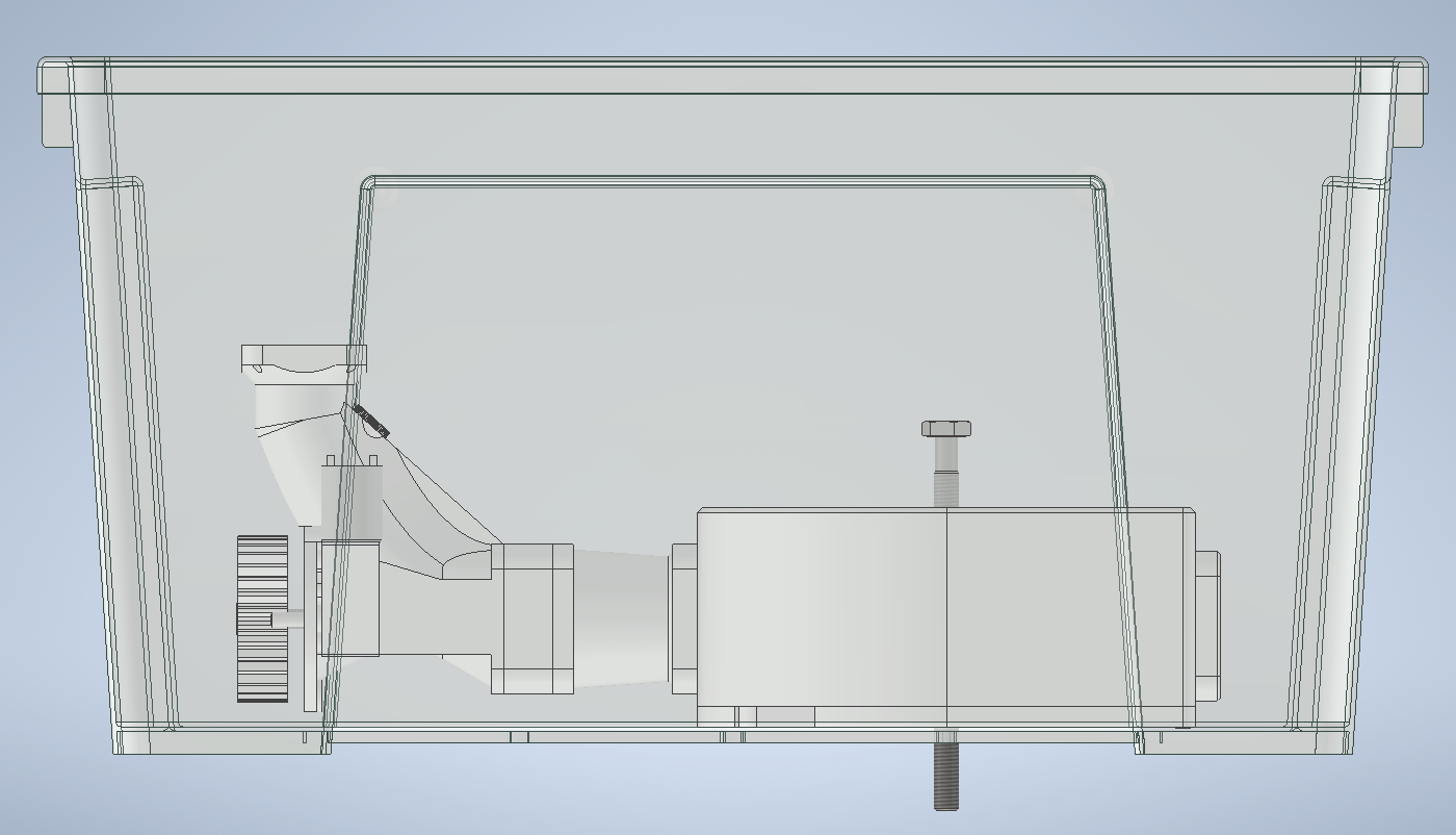
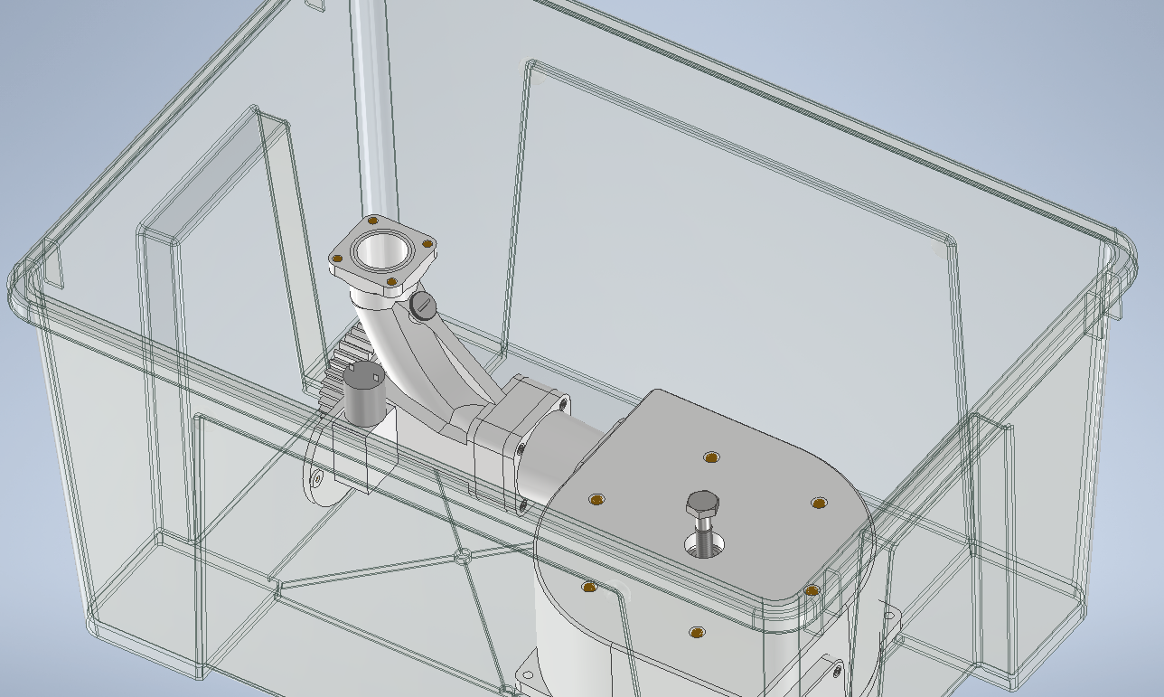
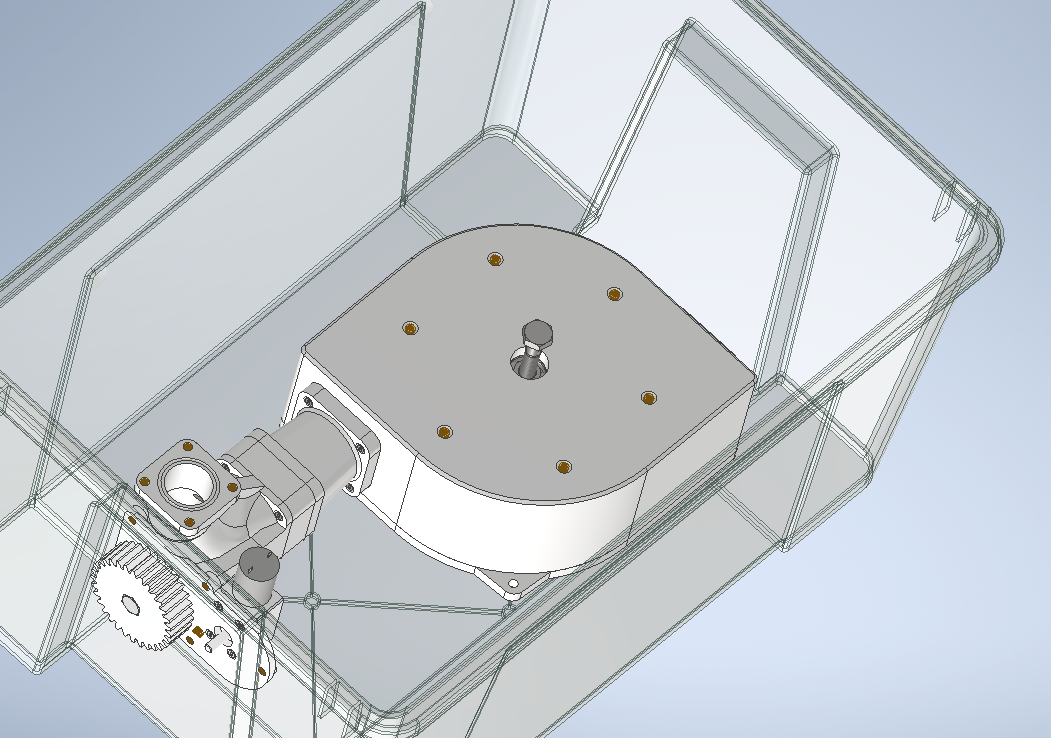
- To make the system easy to transport, I looked for a suitable housing and decided to use one of the Ikea SAMLA boxes (45L) (https://www.ikea.com/de/de/p/samla-box-transparent-30102974/). On the one hand because the size fits my purpose well and on the other hand because these boxes are cheap and available internationally. Seems like Ikea has created a box-standard here. :D
I could imagine that the complete system would later fit in three of these Ikea boxes.
One box for the turbine, generator and associated inverter/battery manager. Another box as a storage or transport case for the required hose/pressure line and the third box can be used as a water inlet including filter system.
![]()
![]()
![]()
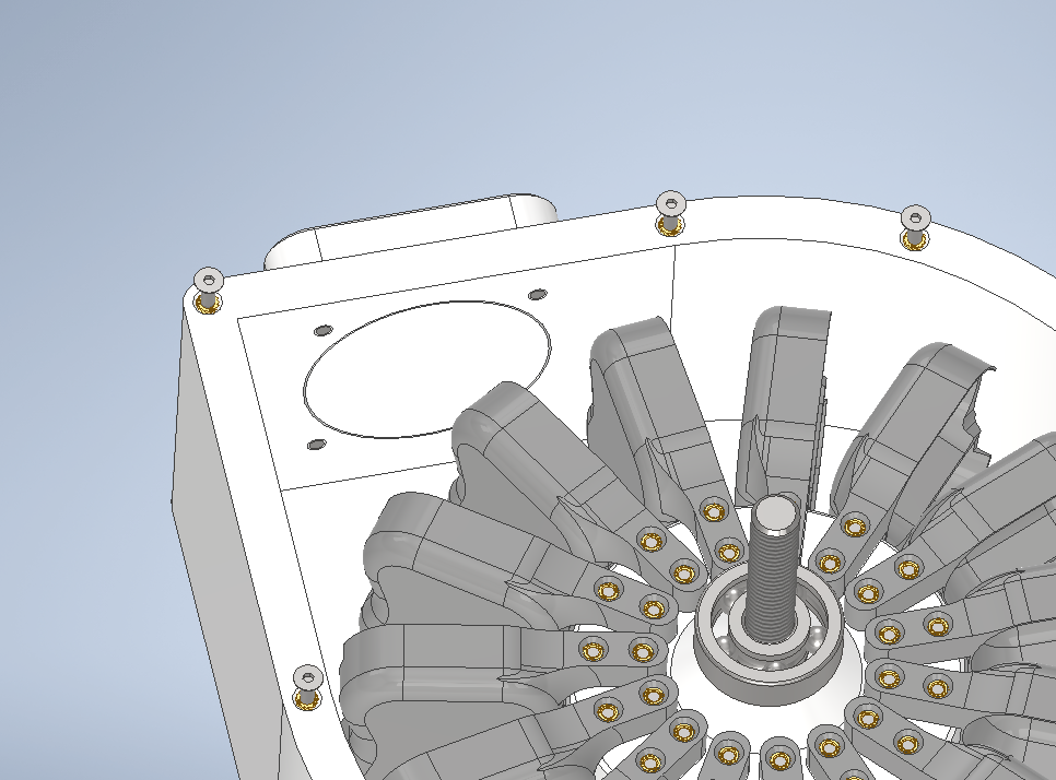
printon_turbine in Ikea samla box. On this picture you can also see the mounting holes for the generator. ![]()
- I also looked around for a suitable generator. In the future I will probably also offer a 3D printed generator as an alternative. Until then, the following should do it first.
What do you think about the current state? Let me know your thoughts. :)
-
More info about the concept
04/19/2022 at 15:52 • 0 commentsSo far the description of this project is a bit thin, which is why I want to give some more information about the planned concept.
GoalsThe basic idea is that with the help of the printon_turbine the manufacturing, assembly and installation of a renewable energy source powered by hydroelectric power is easy to realize even for beginners.
A large part of the parts should be able to be produced with a standard 3D printer. This means that the components do not have to be laboriously manufactured. They can easily be made on a 20x20x20 cm print bed of a standard 3D printer. As far as possible, the remaining parts should consist of standard mechanical parts that are readily available and, if possible, also reusable.
In the event of any damage to the system, it should be easy to reprint and replace the required parts.
In addition, the system should be as compact as possible and easy to transport. In this way, the system could be manufactured at a central location, assembled and then delivered to the location where it is actually needed. Here I think back to the beginnings of the Corona period, when "face shields" were manufactured in many fablabs and then delivered to surrounding hospitals.
ScenariosFor all of the following application scenarios, an important structural or geographical requirement is necessary: A difference in height and sufficient water at the upper level.
The water at the higher level thus has potential energy, which is (with the help of the printon_turbine) first converted into kinetic energy and then (with the help of the generator) into electrical energy .
From my point of view the following possible usecases should be possible:- The turbine is used as a permanently installed system where the water in the upper level is refilled by the natural water cycle. This mostly works in sufficient quantity in mountainous regions where the rained-off water runs down the slope in streams. Here it is easily possible to take some water from these streams to feed the printon_turbine.
- The turbine is used in a pump storage system. For this purpose, in energy-rich times (e.g. during the day when there is a lot of solar and/or wind energy available), water is pumped from the lower level to the upper one. As soon as little or no renewable energy is available, the water can be released from the upper level via the printon_turbine and usable electrical energy can be generated from it again.
- The turbine is used as an emergency power supply. For this the turbine could generate electrical energy using the water supply network. To do this, the turbine is connected to the water supply. Instead of using the water pressure resulting from the height difference between two water levels, the water pressure generated by pumps in the waterworks is used. Admittedly, this application scenario would have very poor efficiency and environmental balance. Also it would be expensive. That's why you should really only consider this application scenario in an emergency. In addition, this only works during a local electrical power failure. If there is a widespread power outage, the pumps in the waterworks would very likely also fail soon.
PowerOf course, high power outputs cannot be achieved with a system of this size. In my opinion, there are two major limiting factors.
- On one hand the size, because so that everyone can rebuild the printon_turbine, it should be possible to produce it using the generally available 3D printers. Most print volumes are close to 20x20x20cm.
- On the other hand, the material, because ultimately the parts are made of plastic. Of course there are different materials with different properties. I'll have to find out what works best.
I will present my current ideas and solutions for these goals in another log. :)
 Fabian