 Shawn Alfaro
I plan on using donor hobby servo controller PCBs to convert the "dumb" toy servo motors into proper hobby servos so that I can plug them easily into a Pi hat that can control up to 16 servos and have complete control.
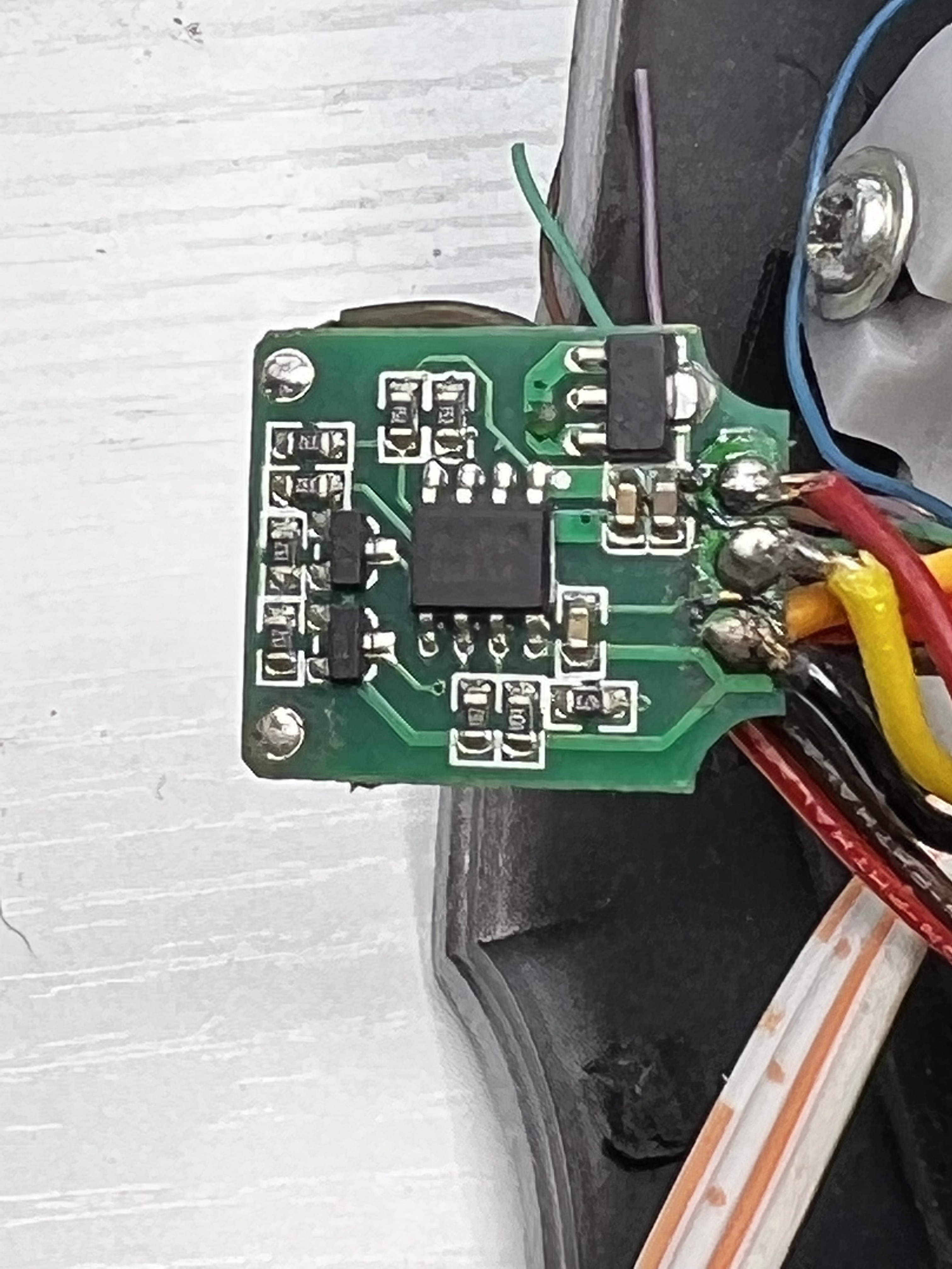
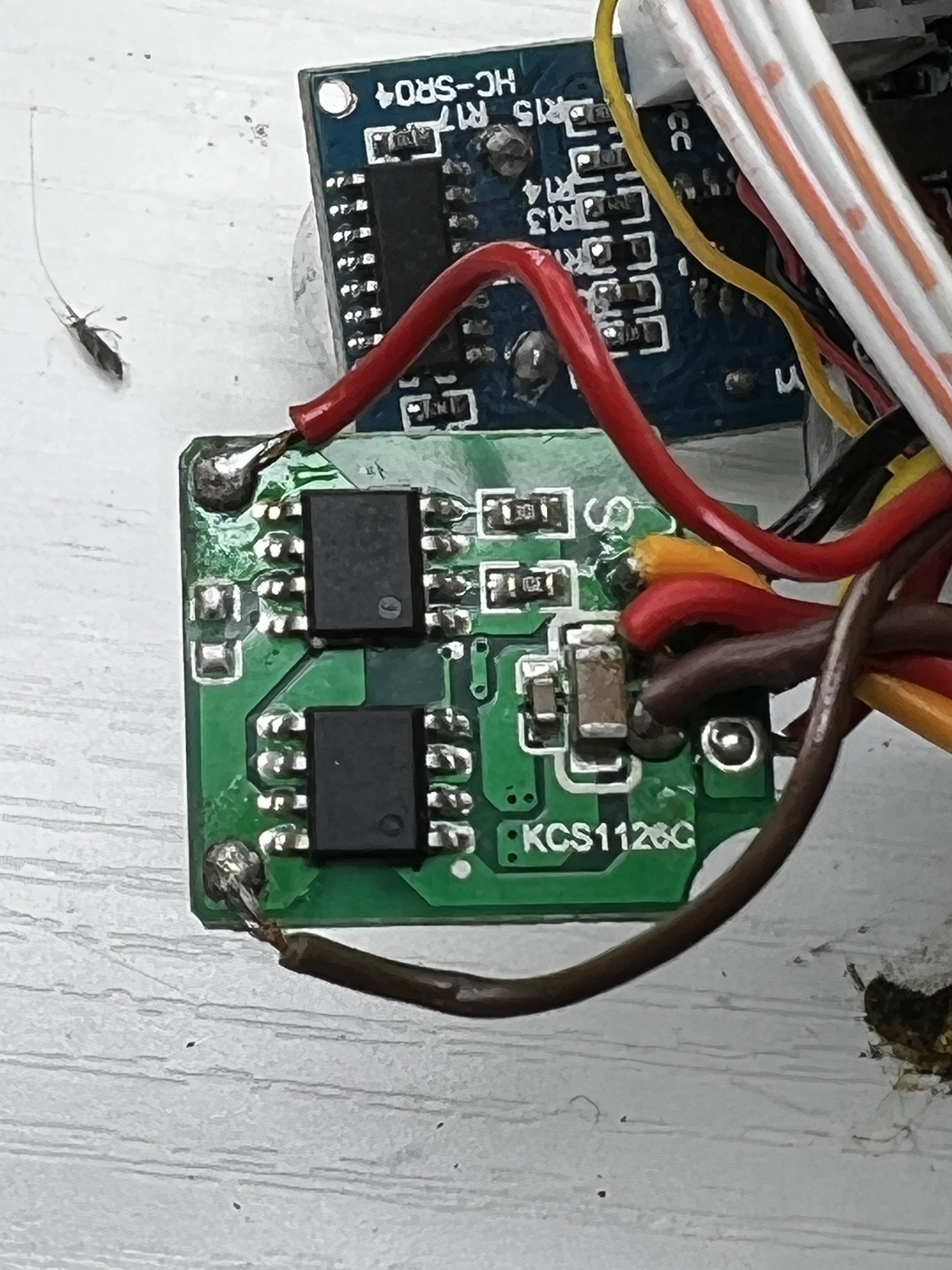
But the thought of using perfectly good servos like this makes me cringe. So i found what driver chips are on one of the already donated servo PCBs, the data sheet and the schematic for almost the entire circuit!
Components that I know of:
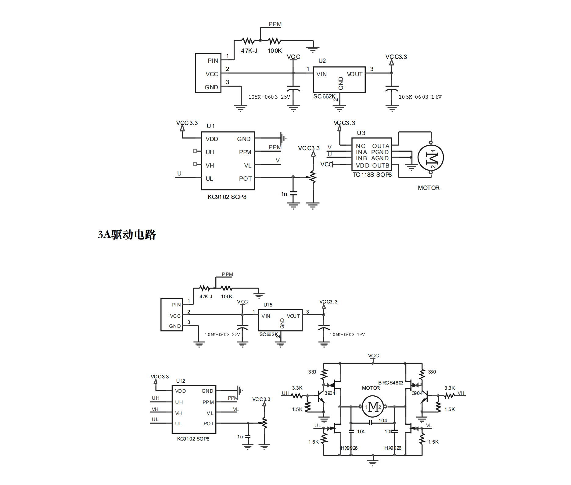
- Controller Chip: KC9102 data sheet http://www.kcsemitech.com/upLoad/down/month_1902/201902261540192521.pdf
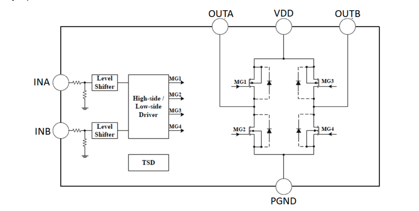
- Motor Driver chip: HM17L data sheet https://pdf1.alldatasheet.com/datasheet-pdf/view/1238745/HMSEMI/HM117L.html
I believe a more competent person than I can help me design a custom PCB with these chips so that I can use it instead of tearing apart perfectly good hobby servos.
If anyone reading this is interested in joining me to help out designing a custom servo driver board like the one I took out of a hobby servo,
DO NOT HESITATE TO CONTACT ME!!!! PLEASE HELP ME OUT!!!!!
I also need help identifying the other components, well atleast the values ill need because i know theres a lot of resistors. I just do not know enough yet to identify the other components, so if you wanna chime in, feel free!
Discussions
Become a Hackaday.io Member
Create an account to leave a comment. Already have an account? Log In.
I discovered your project due to a low level curiosity of servos. My thoughts on the theory of operation.
Job of the KC9102 chip:
Compare the voltage of the pot (0-3.3v) with an amplified voltage of a low pass filter of the pwm signal. Assuming 5V on the pin, it goes through 2/3 voltage divider for 3.3 volts. The low pass filter of 3.3 volts with a pwm duty cycle of 5-10% would give .165 to .33 volts. I would assume that this comparison range is amplified to be 1.65 to 3.3 volts from the PPM signal to be compared to the wiper of the pot (0-3.3volts). It could be that the pot is voltage divided by 10 for the comparison with of lower voltage values instead.
The result of this comparison is UL/VL being in one of (hopefully)three states. 0/0, ?/0, or 0/?. A voltmeter to the UL or VL pin with the servo disassembled would confirm the output voltages by manually sweeping the pot with the pwm sending a 7.5% duty cycle.
I think that there are 4 chips doing the job of the H-bridge. There are two 3904 transistors and two dual-mosfet ICs. The three states control the flow of current through the H-bridge. I think the transistors are being used to keep the 'high' mosfets in one state to keep the flow of current open for servo operation.
The mosfets control the current flow, so perhaps a custom board would provide support for beefier motors by using mosfets of a higher current rating?
Are you sure? yes | no
thanks for your research. I have been also ripping apart mg995 servos to get their pcbs to make bigger servos. I think this data will be useful to make a custom pcb. If I do i will put it on github for further collaboration. Unfortunately, I can't seem to find this ic online to buy for experimentation
Are you sure? yes | no
FYI, The KC9102 is a programable chip. There are functions in there you can change. Unfortunately only a few know how and I am not one of them. You need to know the special programming codes to gain access to it and then you can adjust stall and other parameters.
Are you sure? yes | no
what is the chip exactly?
Are you sure? yes | no