 Phil Wright
Well the latest batch of PCB's have arrived. Finally I have a simple 32 bit fixed value board. This allows me to set a 32 bit value using dip switches so I can then feed that value into other boards as test values. This makes debugging so much easier.
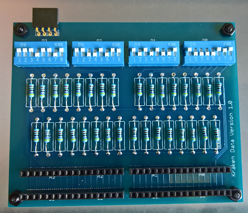
I must have picked the wrong component in Eagle to represent a standard resistor because you can see that the space allocated for each one is much greater then really needed. Fortunately it does not really matter as there is plenty of room on the board anyway. Although, adding 32 pull up resistors seems like I am doing things the hard way. There must be a simpler way of achieving the same effect? Any ideas?
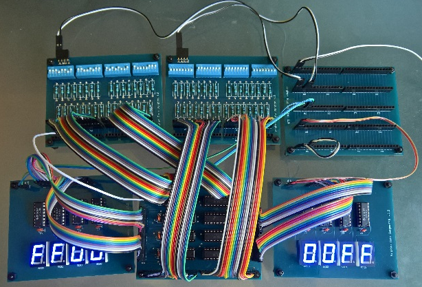
I used the boards straight away to test each of the 2-1 mux boards I have built. I can set two values going in and then use two display boards (each display board only shows 16 bits) to show the 32 bit output. Then just toggle the output select line and instantly check it works as expected.
Next up was checking that each of the register store boards works. I need a total of 16 for the 16 general registers in the RISC-V ISA. Unfortunately I ran out of components once I have built 10 of them but it still makes quite the impressive vertical stack. The input and two output ports are all connected vertically Arduino style as is the power supply connector. That just leaves a 3 pin right angle connector for each register that allows for per-register selection for output and writing.
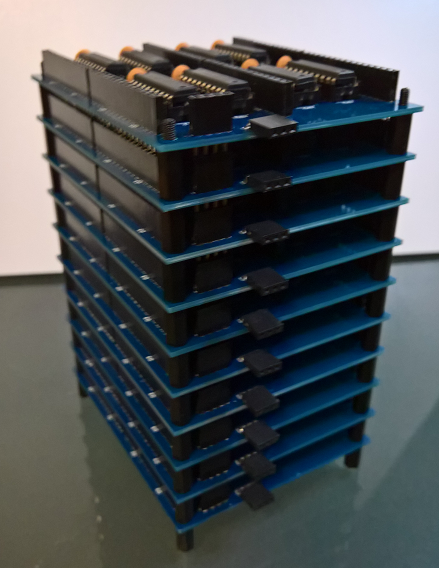
My next job is to get the components ordered to finish the stack and then the board that will be needed to generate the 16 sets of control outputs for them. Then finally the first major block of the CPU will be completed, the general register file.
Discussions
Become a Hackaday.io Member
Create an account to leave a comment. Already have an account? Log In.
I like it! I've always wanted to use thumbwheel switches for this kind of thing. Hexadecimal thumbwheels seem hard to find, but you could do octal on 10-position switches (and just ignore 8 and 9). They're cheap these days on ebay:
http://www.ebay.com/itm/10PCS-22-8MM-DECIMAL-0-9-DIGITAL-PUSHWHEEL-THUMBWHEEL-8421BCDCODING-SWITCH-KM-1-/261913742626?hash=item3cfb468d22:g:BtYAAOSwdsFUN1PN
but, I guess 10 octal digits is only 30 bits - you would have to go to eleven!
So, on another note, have you noticed that it's difficult to get long stacks of boards mounted on standoffs? I did this with my diode clock, and by the end of the stack, it was always difficult to get the last few boards on. Maybe the standoffs were not all exactly straight, or they were not aligned in the holes correctly, or whatever, but it was a real pain. The only way I got it to work was by not tightening them until all the boards were on, then going back and using wrenches to tighten them all "at once". I didn't have black anodized standoffs - so I had painted them, and the wrenches would leave marks.
Are you sure? yes | no
that's why *real* engineers use backplanes ;-)
Are you sure? yes | no
or a wide ribbon cable. might even be cheaper than the stacking headers
Are you sure? yes | no
ribbon cables are ok for straight signals.
when you want to do some smart routing (like I do), however, you need a PCB.
Are you sure? yes | no
was meaning in this specific case since he has common lines between all of the boards, but I see what you're saying.
Are you sure? yes | no
Yep :-)
Now look at
https://hackaday.io/project/14628/log/50427-how-to-balance-a-fanout-tree
Are you sure? yes | no
A resistor network would use less room too :-)
Are you sure? yes | no
Definitely will do that once I getting further along.
Are you sure? yes | no
Wow !
One other thing to do is to interface some computer/microcontroller to generate values on demand, such that "test vectors" can be repeatedly fed to the circuit.
Are you sure? yes | no