 Phil Wright
Instruction decoding is one of the simpler parts of the system. For example, all the branch instructions can be identified using the same 7 bits of the incoming instruction value:-

All branches have the same '1100011' pattern at positions [0-6]. So I only need a single decoder board that compares and matches this 7 bit sequence in order to generate the correct control lines for the rest of the CPU. The actual comparison of registers rs1 and rs2 is performed by a separate comparison board. This comparison board takes as input the 3 bits at positions [21-14] that uniquely identity the actual branch operation. So '000' will mean BEQ and '001' BNE and so forth.
This same approach works for other major groups as well. All the ALU operations that take an immediate value have the same '0010011' pattern. The ALU operations that take two registers have the '0110011' pattern. In both cases the ALU implementation will perform the correct function by using the function code that is part of the instruction format and passed directly to the ALU.
By grouping this way we only need a decoder board for each instruction group that we need to support. As I am only implementing 37 instructions it works out I will need 9 decoder boards.
A single board looks like this:-
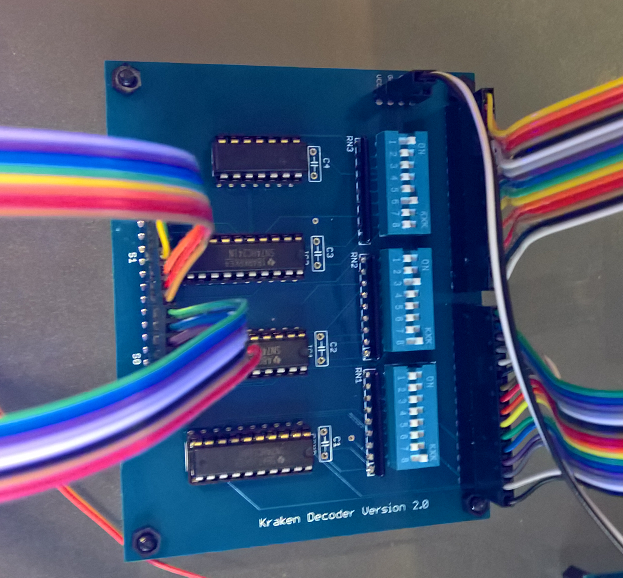
At the bottom right is an 8-DIP switch that is used to match against the incoming first 7 bits. This means the left most switch on this DIP package is not connected and ignored, but it is easier to order and use 8-DIP packages than try to find ones that support exactly 7.
Above that are two more DIP packages that are used to define the 16 control output signals. I am assuming that my final design will not have more than 16 different MUX or other boards that need control lines!
By making the board completely configurable I have the flexibility to implement the rest of the CPU in multiple ways and to change the design if needed. Like my other boards these can be stacked vertically because I am using long female headers for the instruction input, control line outputs and the power connection. So I anticipate a final setup with 9 of these high.
I use a 74HC688 for the bit pattern comparison, 2 x 74HC241 output drivers for the 16 control lines and an 74HC04 to invert the output of the '688 for use with the output drivers.
Discussions
Become a Hackaday.io Member
Create an account to leave a comment. Already have an account? Log In.
It occurs to me that you could radically simplify this section of your design. The last two bits of the opcode portion of an instruction are always 11. You could, sacrificing correctness, ignore them. That would leave you with 5 opcode bits. At that point you could replace all of your comparators and switches with a 5-to-32 decoder. Granted, you'd be ignoring most of the 32 outputs of the decoder, but it would basically cut things down to two '154s.
Are you sure? yes | no
Ah, the power of the decoder...
It's a learning curve, yes, and there is hope : Phil has already evolved the register set to avoid the use of countless '688s :-) With the '138 and '238, we can do so many things :-)
Are you sure? yes | no
Not sure that would work. Some of the instructions need to enable MUX1, some would need to disable MUX1 (output the alternate input) and yet others it does not matter because the output of MUX1 is never going to be used. That does not seen to translate into a 5 -> 32 conversion.
Are you sure? yes | no
My first version of the decoder has two boards per group of instructions with an interconnect between them. So I have already halved the design!
Are you sure? yes | no
I expect MIPS to be designed with a lot of hardware tricks and simplifications, I have never seen magnitude comparators inside the decoding logic of a processor (except to compare register numbers between different pipeline stages). I'm sure you'll come up with more simplifications with time :-)
Are you sure? yes | no
To clarify, you might need stuff other than the decoder for each opcode group, but a decoder is equivalent to (and less complicated than) a bunch of comparators and bit masks. Right now you (if I understand your description) are planning on having one '688 for each of the 9 valid values of the opcode section of an instruction. That part of your circuit could be replaced with a single decoder.
Are you sure? yes | no