 Ken Yap
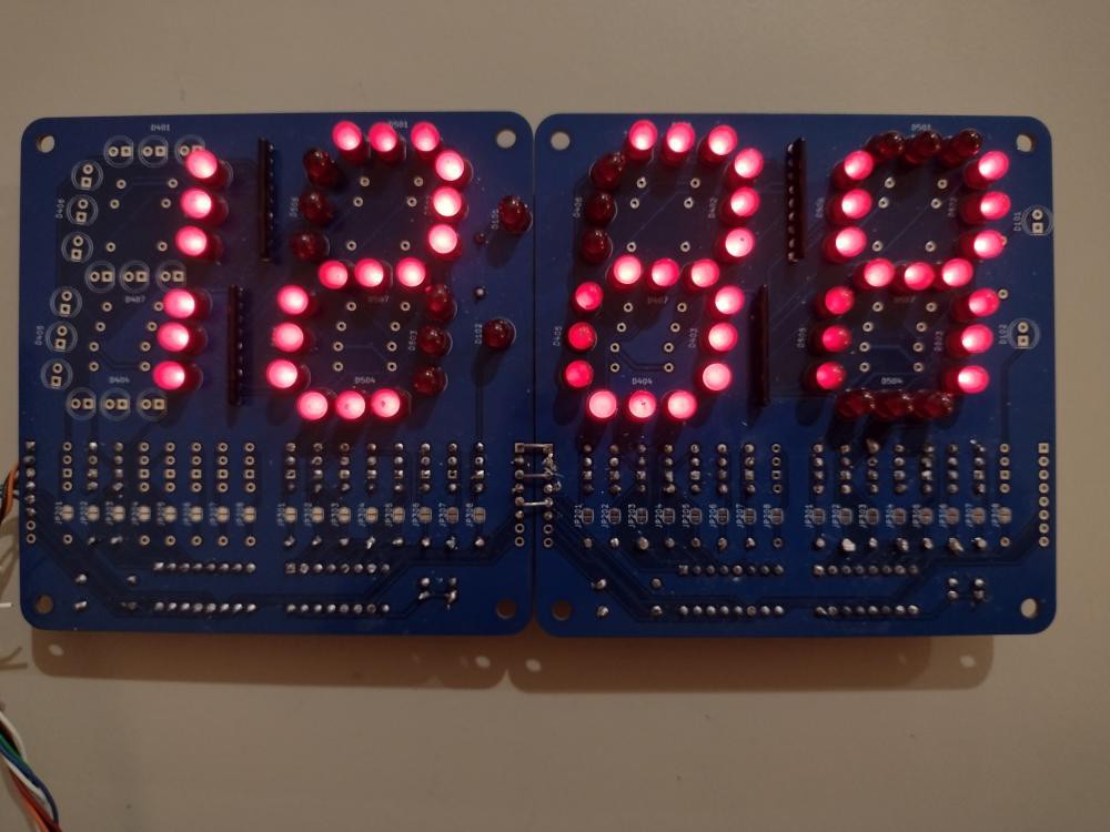
While waiting for PCBs for another project, I decided to revive more old boards and components. The board in question is a 12 hour clock display with 3 LEDs per segment that I made in the late 70s. A few years back I got it working again with the original clock chip as detailed in this short writeup. However I was not happy with the disparity between the clock chip voltage and the LED voltage, about 25V and 12V respectively, requiring a zener diode running hot to take up the difference. The display board is still functional so I decided to replace the clock board with one I designed a couple of years back using the 8048, which is from the same era, and which I have several idle boards for.
I've only made 24 hour clocks of late so I spent some enjoyable minutes augmenting the assembly language firmware with a 12 hour option.
Despite the age of the LEDs, they are still attractive and even, albeit less efficient than modern ones. Each segment draws about 30mA for an effective 7.5mA with 4 multiplexed digits. Modern LEDs would only need a mA or two for the same brightness so efficiency has increased several-fold over the decades. I may be nostalgic but I am fond of these LEDs, by National Semiconductor or TI. The diffusing dome spreads the light very evenly, resulting in large dots, unlike some modern LEDs where you can see the point source die. Also I had painted the front of the phenolic PCB black for best contrast.
I know of another clock made at about the same time, based on the MM5314 clock chip, using the same type of LEDs, which has run almost continuously up to the present day. Some of the people who were involved with that clock are no longer with us. ☹️ Electronics can be very long-lived.
Update, 2024-03-19: I got tired of the unreliability of the old one-sided phenolic board. Also I had wired the LED segments with cathode digit drive which required some extra transistors to invert the signal. Seeing as manufactured PCBs are very cheap nowadays, I took advantage of an Elecrow offer of $1 for 10 PCBs. With shipping, it came up to $1 per PCB delivered. I even got blue soldermask for no extra charge. It arrived within 2 weeks even with the cheapest shipping option.
As you can see from the picture at the top, I designed the board to be cascadable by using the versatile 74HC595 shift register which only requires 3 lines to drive, plus power. Two boards stiched together with jumpers form 4 digits. No more multiplexing. You can see there are lots of driver transistors and base resistors. I'm not short of those; I still have a bag of cheapo transistors from all those decades ago. Transistors are only needed for these old LEDs due to their inefficiency and higher current draw. Modern LEDs can be driven directly from the 74HC595 and solder jumpers allow the transistor to be bypassed. The LED current limiting resistor is a resistor network which reduces component count.
I had hesitated to take this step because I feared breaking the LED leads during desoldering. In the event I didn't break a single LED because the LEDs were mounted a little above the board and I could push the leads above the copper, after removing the excess solder with a sucker.
So this is a bit like the proverbial axe that has had 10 handle replacements and 8 blade replacements; is it really the original axe? But in this case the LEDs are really the ones from decades ago. Probably they will last longer than I will.


 Mike Moretti
 makufelis-xyz
 P
P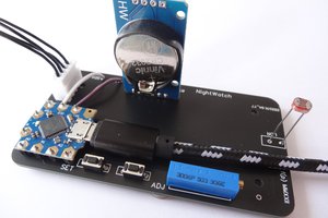
 Mark Wilson
Nice Clock!