The actuators are a fundamental part of this project. One actuator could be custom designed for each joint, this would possibly provide benefits regarding mass and volume. To reduce complexity and manufacturing costs, the same actuator is used for both joints.
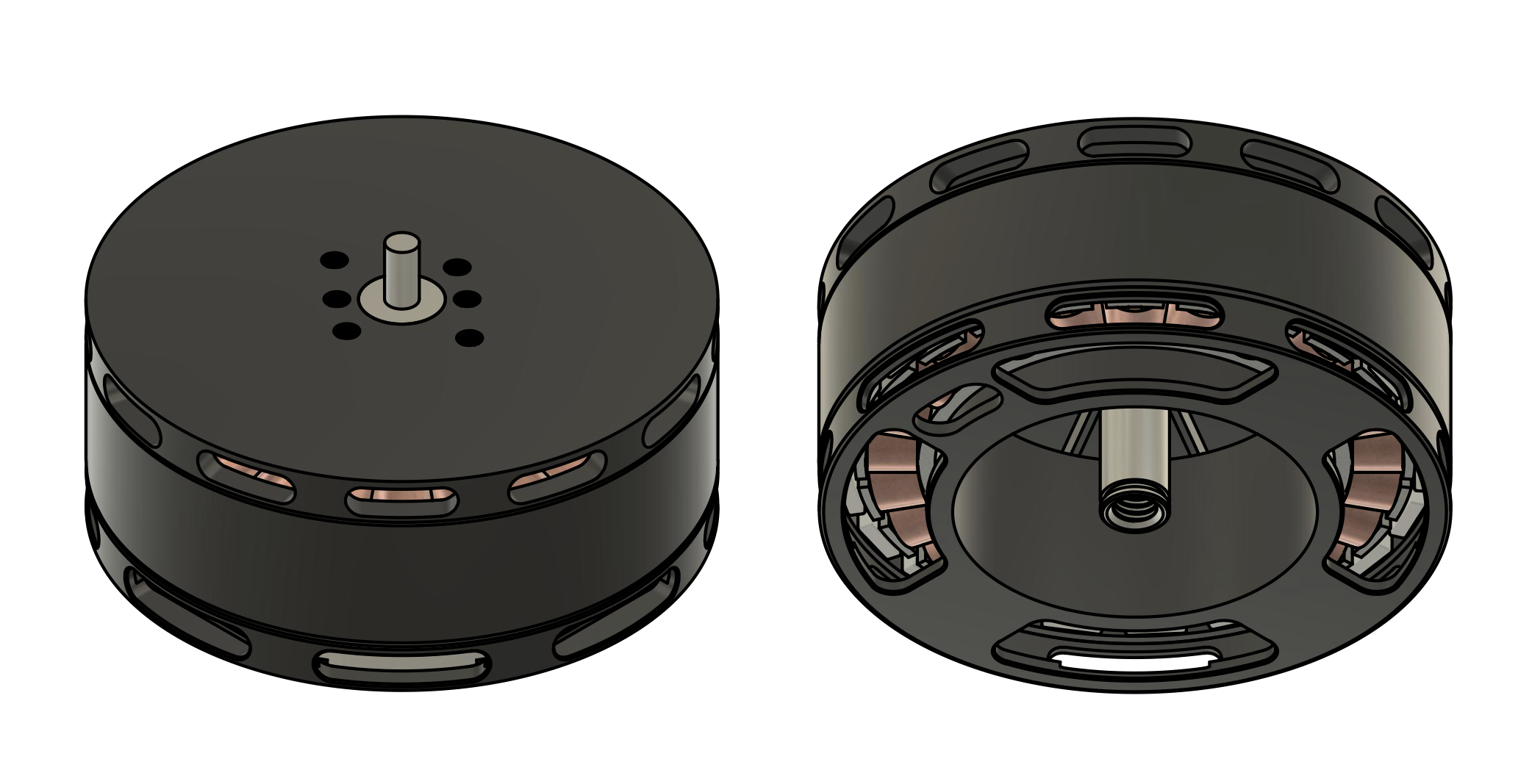
To achieve the actuator concept, inexpensive hobby drone motors are used in combination with [the cheapest] ball screw reductions. After having the physical motors on hand, I partially modeled them as accurately as possible. The CAD models aren't available on the internet. The center hub with the bearing seats was not modeled due to the fact that I already knew it would have to be removed.

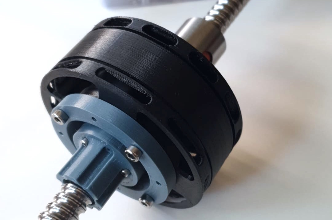
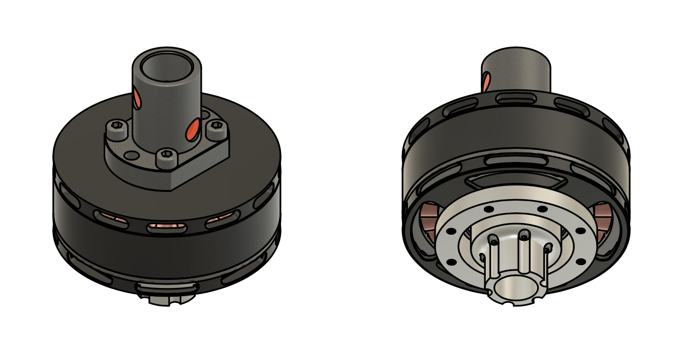
To achieve the concept, the motors have to be modified in order to allow the screw to pass through, and the ball nut has to be attached to the rotor in some way. The resulting axis has to be bore. Furthermore, the stock bearings aren't meant to handle high axial forces, so these have to be changed for others which allow this. To handle this axial forces, new angular contact ball bearings are placed. These come in a pair arrangement and there is a specific way to mount them.
The design process was iterative. I created a first generation model with modifications, printed a 3D mockup of it, and exchanged ideas with the machinist that would perform the modifications and manufacture the new pieces. The first generation actuator involved creating an entirely new rotor with included axis, which would incorporate the section of the original rotor which holds the magnets. Several instances with the machinist were required before achieving the final design. He gave insight into what design aspects made the costs lower and reduced fabrication complexity.

The final design retains the original rotor, and new pieces are created, such as a new axle, bearings seats and what I call the rotor assembly crown, which presses the assembly together using 6 M2 screws. The crown gets its name because of its shape, and the shape is such because it allows for the mounting of the encoder disc. The ball nut is held through 4 M4 screws in a sandwich configuration which presses the new axle, the rotor and the nut together.

The actuator modifications turned out to be quite complex. If I could go back in time, I would purchase a frameless brushless motor and design from scratch the necessary parts. At the time, frameless motors with the desired characteristics and price were not found.
 Maximiliano Palay
Discussions
Become a Hackaday.io Member
Create an account to leave a comment. Already have an account? Log In.