Assembling the prototype was the last step to transition into the control side of things. Although I have been designing the control scheme since the beginning, the real tests are about to come. More on this on a future log.
The assembly consisted of two main stages, mounting the actuation system first (joints blocks and actuators), and then mounting the electronics and making the necessary connections. The following time-lapse briefly shows most of this process.
A few snapshots. You might see knee and ankle blocks with metallic paint and raw black. This was because these required a few modifications. The final ones are black.
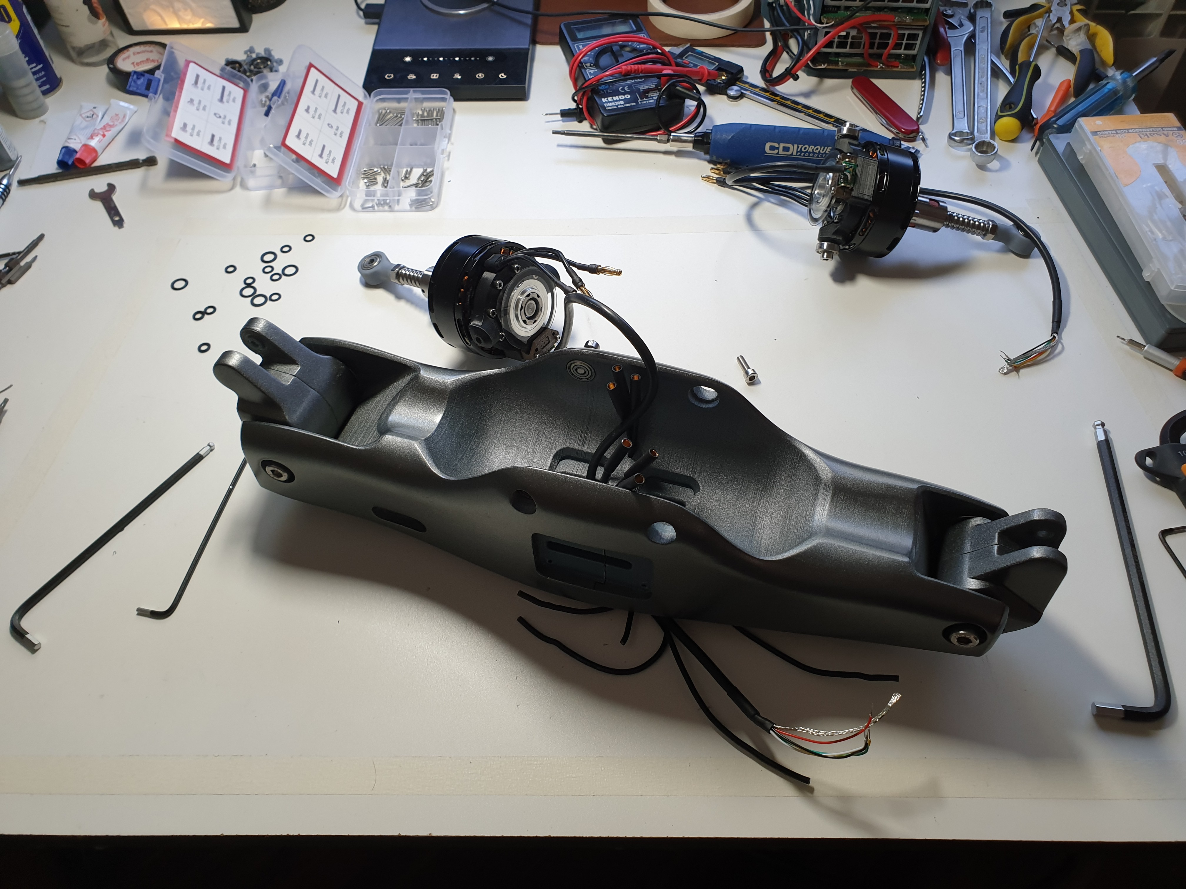
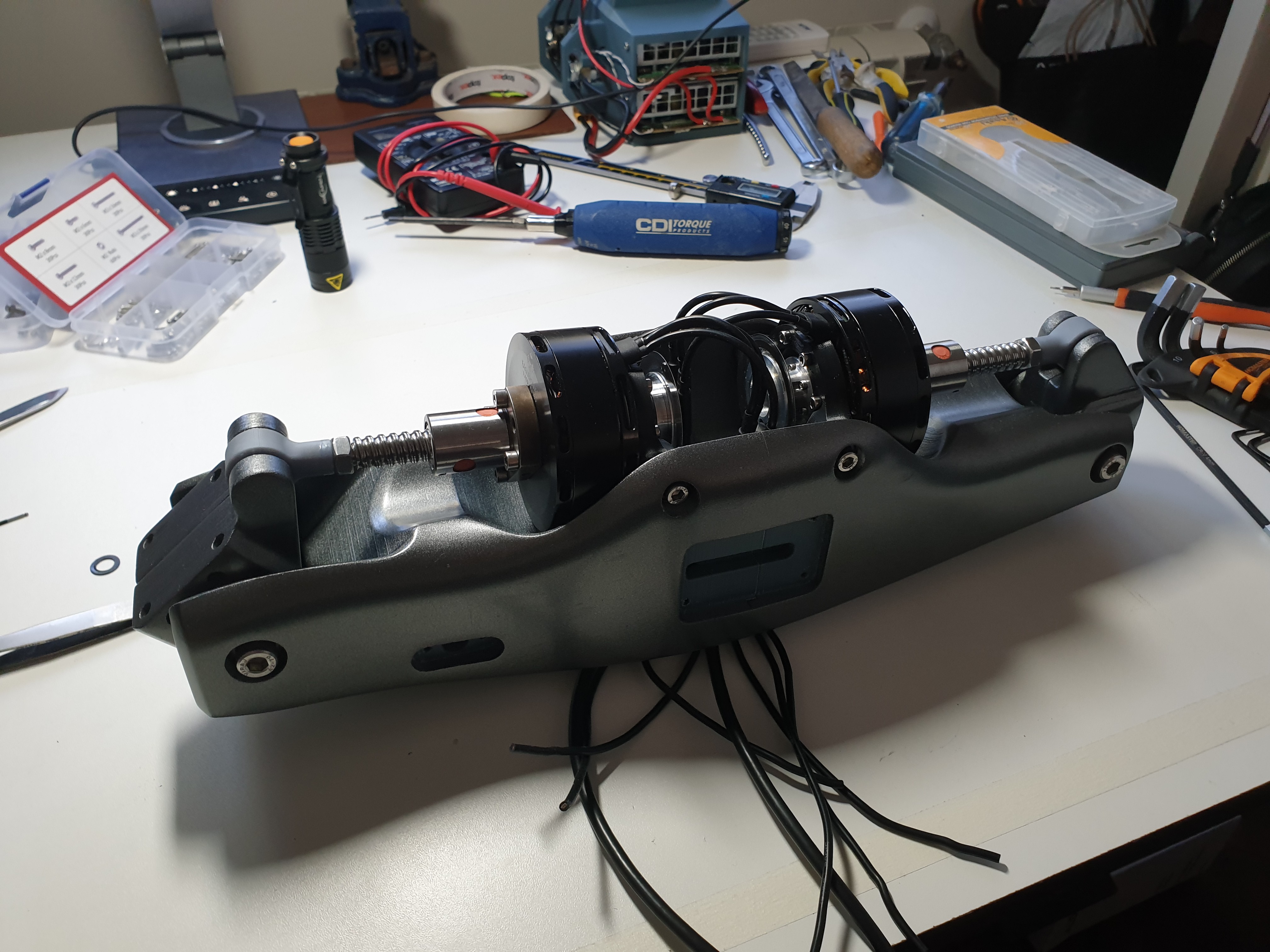
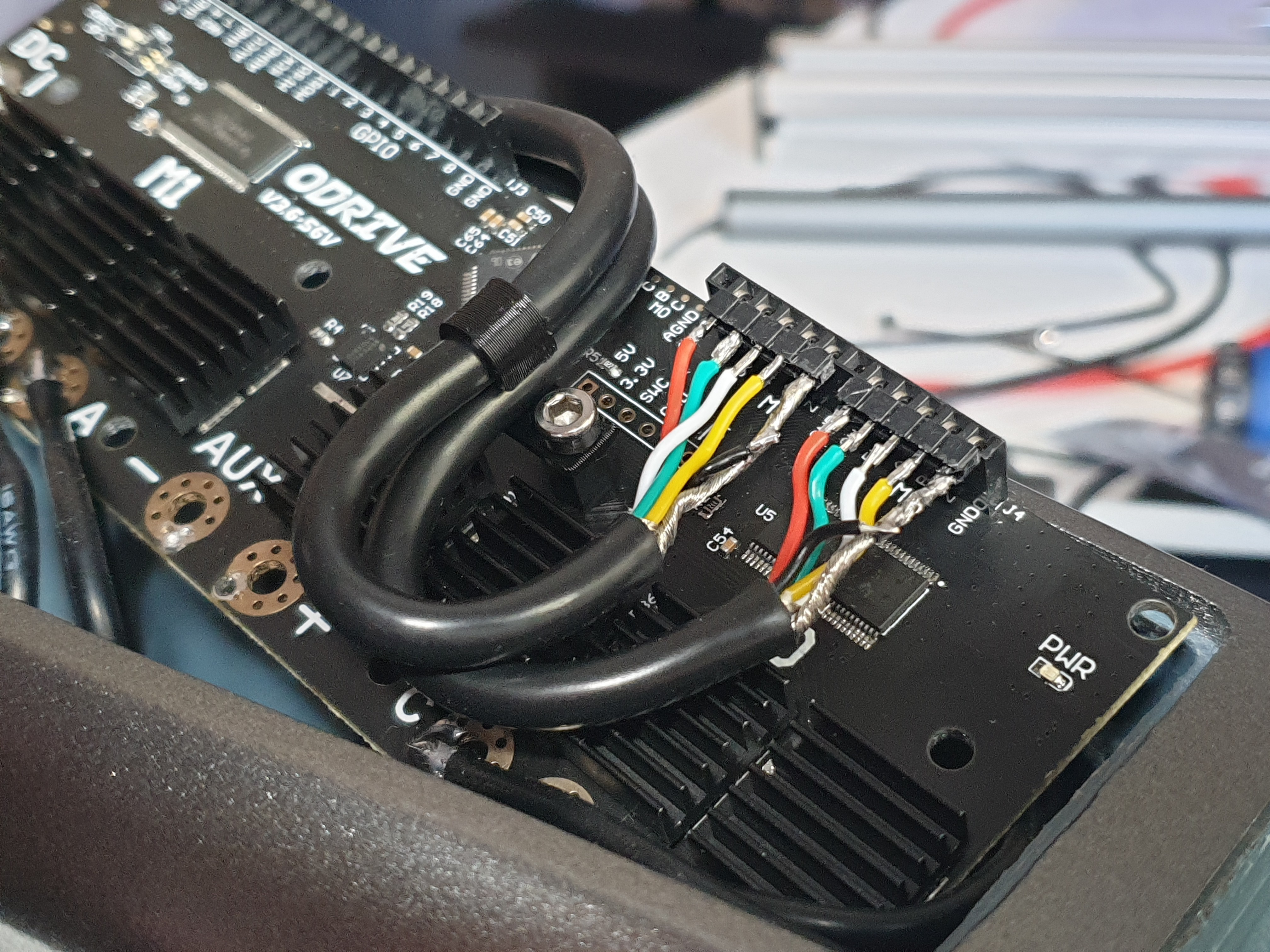
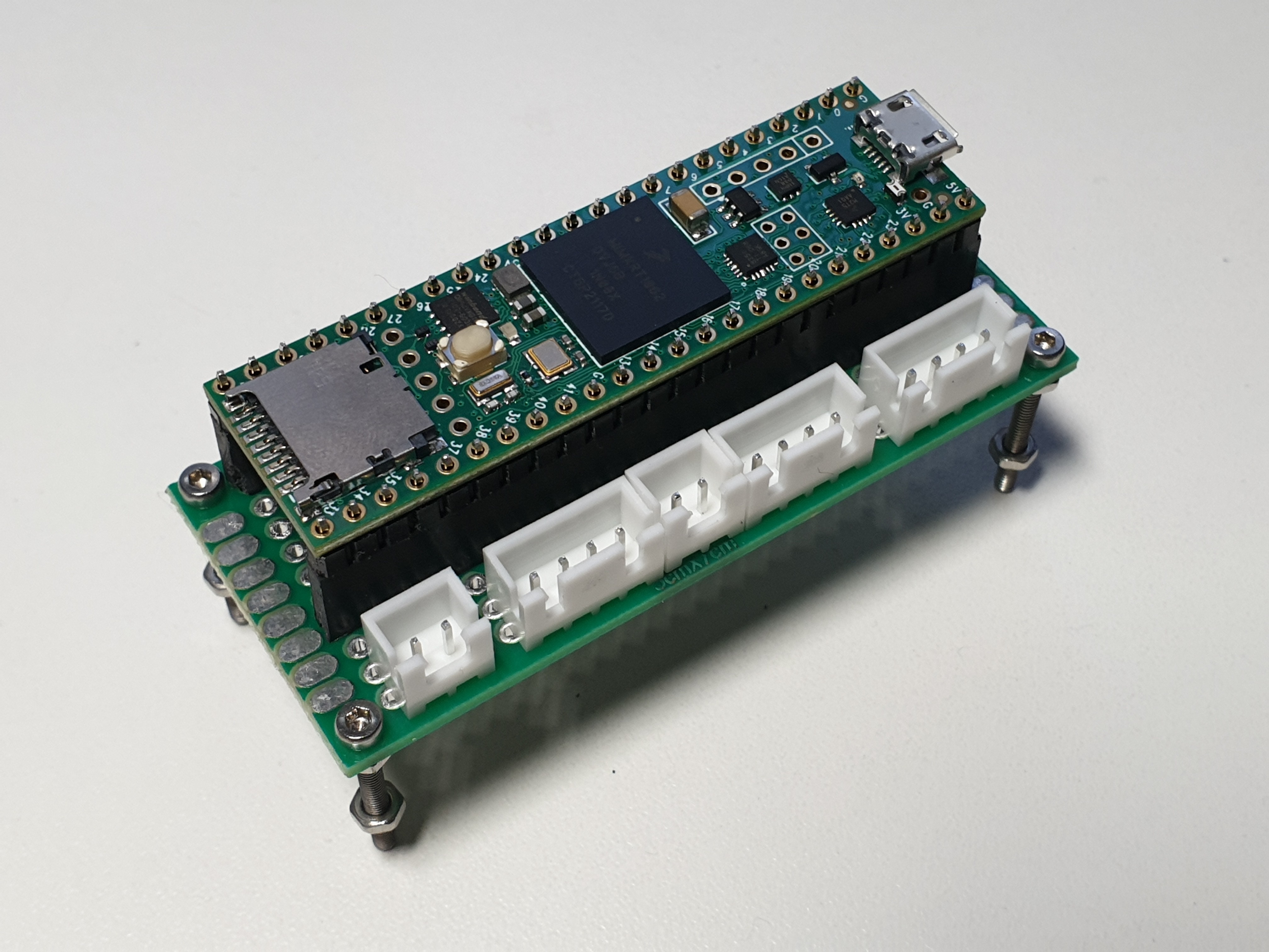
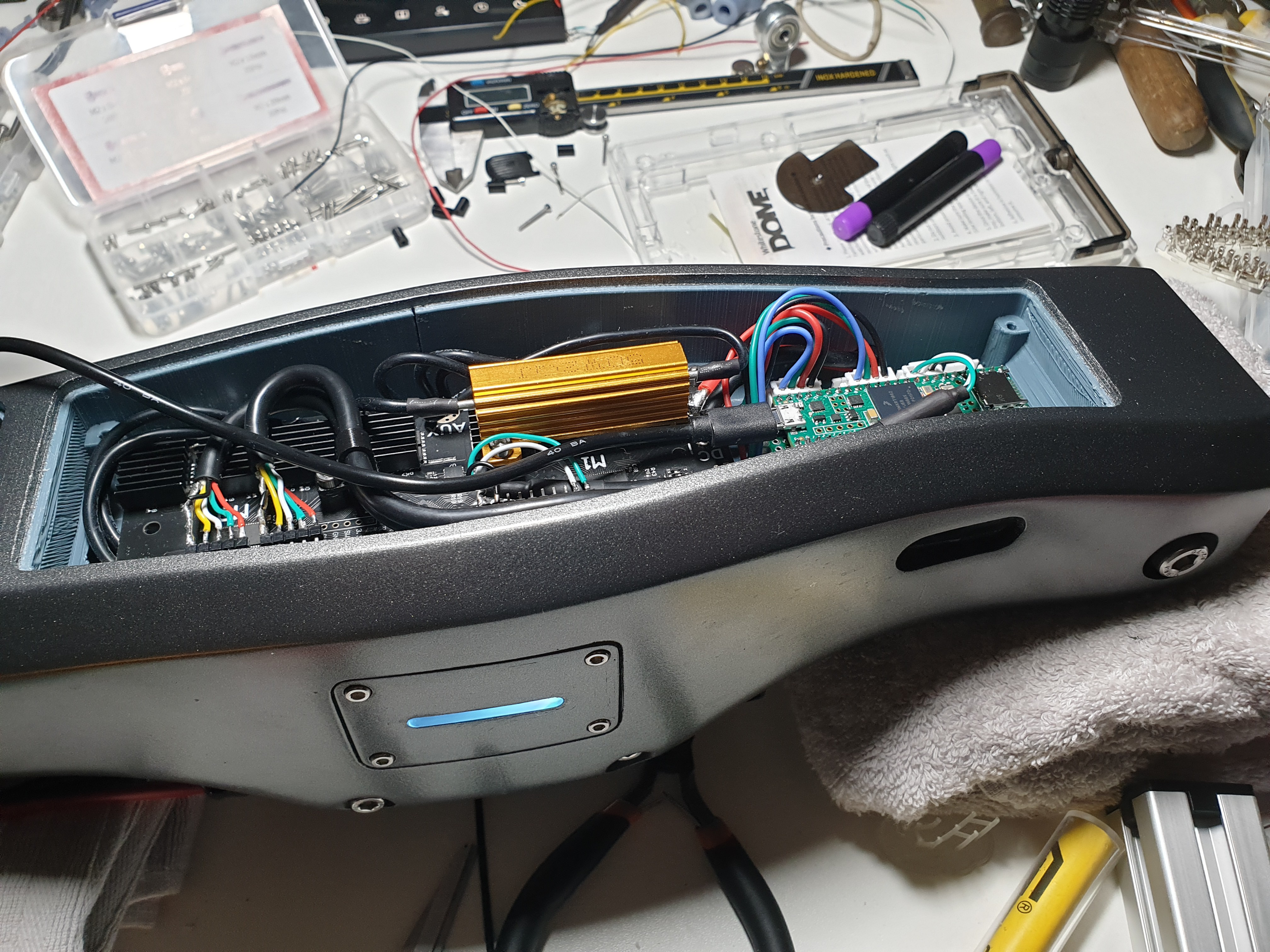
Final knee block with rod end and pyramid adapter in place.Rear view of the prosthesis and unmounted motors with the 3-phase motor cables already passed through channels that communicate the electronics cavity with the back. Both joint blocks are already mounted.Actuation system mounted. Wires are routed and coming out the front cavity.Odrive about to be secured in the front cavity. A 3D printed clip keeps the encoder cables neatly routed.A self built breakout for the Teensy 4.1 with JST connectors for ease of assembly/disassembly. Connectors for power, power and I2C for the IMU, both RGB LEDs and UART for the Odrive.3/4 view of the prosthesis with electronics in place and LEDs on.
 Maximiliano Palay
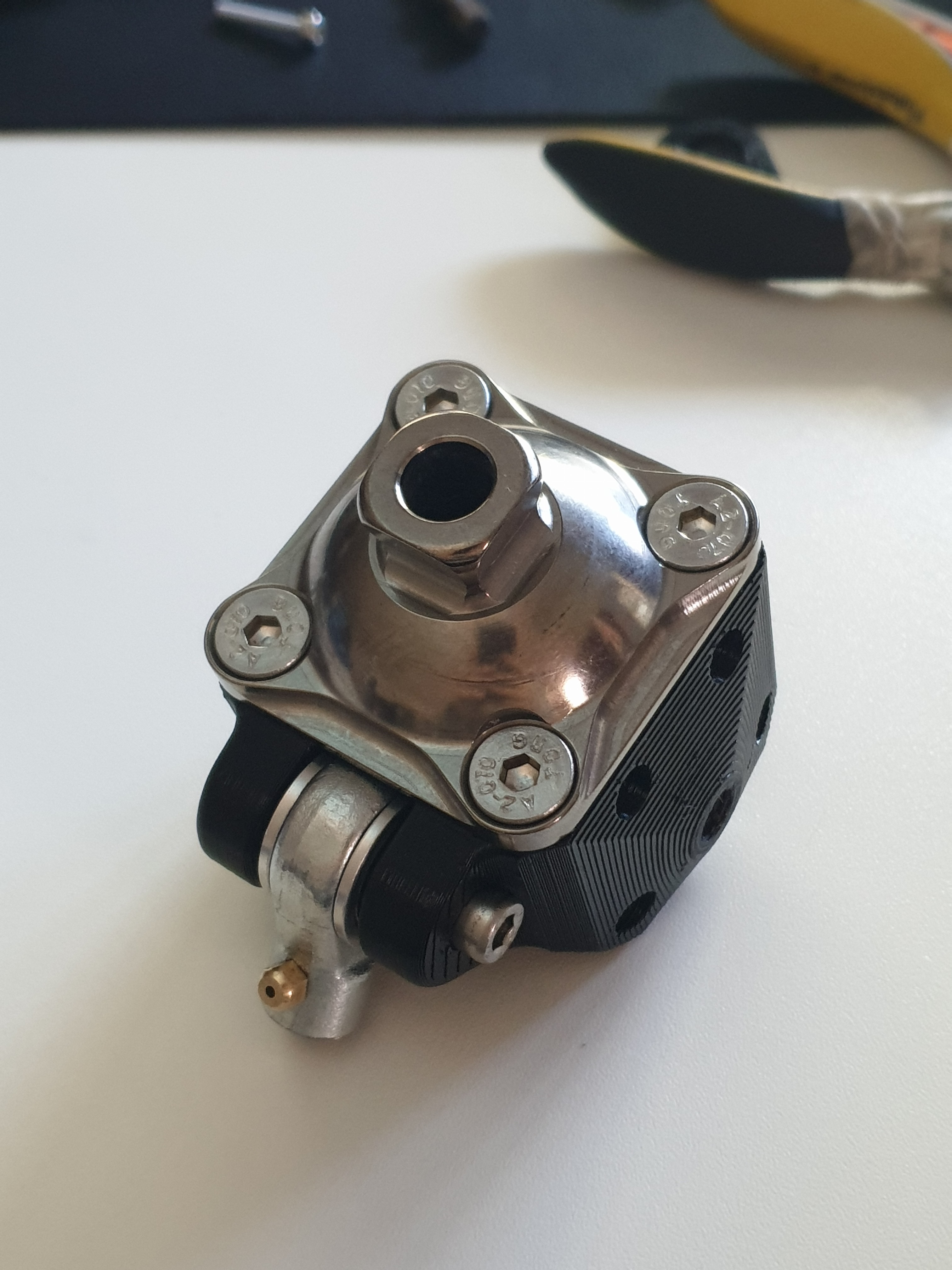
Discussions
Become a Hackaday.io Member
Create an account to leave a comment. Already have an account? Log In.