 Maximiliano Palay
A central part of this project. How is the prosthesis controlled? How does the user have to interact with it?
Typical control systems
Typically, intelligent prostheses use a range of sensors including IMUs, load cells and sEMG. The cheapest of these are the IMUs and thus the ones being used. A load cell could have been incorporated, and is useful to determine different events and gait phases. I couldn't find one with the necessary specs and cheap enough to include it in the budget.
These systems usually have a 3-level control scheme, with a top level which recognizes the user intention, a mid controller which is activated by the higher level controller, which determines the behavior of the prosthesis. And the lower level comprehends the controllers and actuation systems to make things happen.
This project's control, neural networks
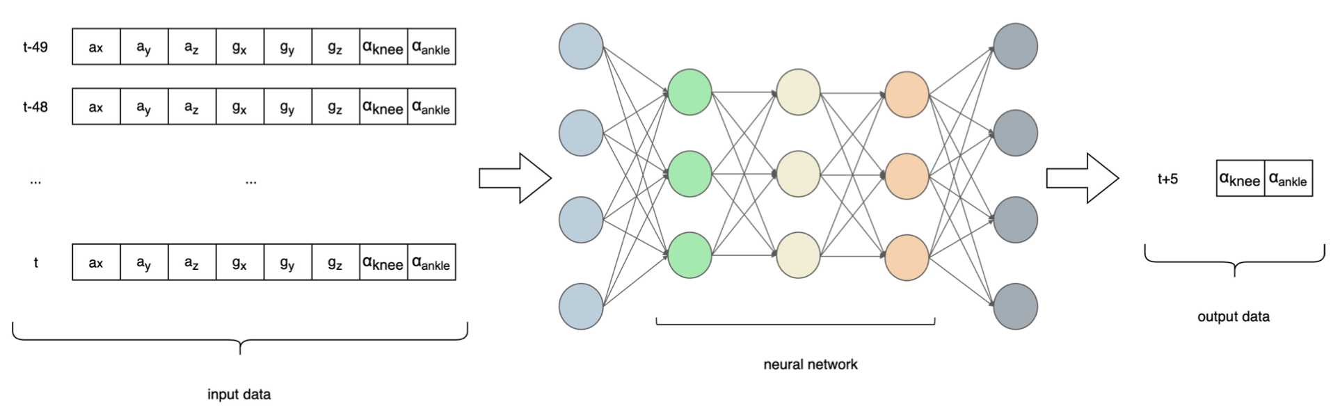
To break down such an immense problem, this project implements a two level control scheme, eliminating the highest level. That being said, the prosthesis always "thinks" the user's intention is to walk. The mid level controller is implemented using a neural network, which takes IMU data and joint angles for the 50 previous time steps and predicts the joint angles 5 time steps into the future.
Why a neural network? The answer results from a previous question, how do able-bodied people walk? The answer is quite difficult, honestly. It is a mostly automated process, we don't put a lot of effort into thinking what we have to do in order to walk. Directly interpreting data from an IMU to detect gait phases would be a hard task to say the least. This is where Machine Learning (ML) comes into play. If the IMU data has a correlation with the joint angles, a model can "learn" the relationship and it can then be used to make predictions.
Several neural network architectures were tested, including RNNs, LSTMs, and CNNs. As the control algorithms run onboard of the prosthesis, memory and runtime restrictions means the model cannot be too big or computationally expensive. This was implemented in Tensorflow, and optimized to run on a microcontroller using TFLM (Tensorflow Lite for Microcontrollers). At the time this was done, LSTM and RNN kernels were partially ported to TFLM, so the final NN had a few convolutional layers and a trailing fully connected network.
Data capturing
To train a neural network, there is a need to have data, lots of it. Typically, motion capture systems (MCS) enable the measurement of different stats that are useful to calculate the joint angles. Ideally, I would have used a motion capture system in combination with an IMU, and recorded data of several subjects walking to train the neural network. I couldn't find any dataset with these characteristics and the amount of data necessary for this application on the internet. Without access to a motion capture system, I decided to build my own. Nothing remotely close to an optical MCS, but at least I can grab data whenever I want to.
So I made this device that attaches to my right leg, with the use of straps and fixed footwear. It was built using 3D printed parts and aluminum extrusions. Two AS5600 magnetic encoders measure the joint angles, and an IMU attached to the front part of the leg, above the knee, measures 6DOF data. These three sensors are connected to an Arduino Nano using an i2c multiplexer (the encoders have hardcoded addresses). The Arduino measures raw data from the sensors, creates a string with all the data in a CSV manner, and sends it through the serial port to a host computer, which registers the data. This happens at 50Hz.
Thanks to my uncle for lending me his treadmill!
Inverse & forward kinematics
The prosthesis does not use encoders at the joint origins. It is necessary to know the joint angles using the motor encoders. This requires a forward kinematics models that, knowing the motor position, enables the calculation of joint angles. This is possible as there are no elastic elements in the actuation system. If elastic elements were present, encoders at the joint axes would probably be necessary.
Knowing the target joint position, we have to know what position the motor should be in to accomplish the target. This uses an inverse kinematics model.
Both problems were solved geometrically, although using different techniques.
Control loop
The control loop was implemented in Teensyduino, and runs at a frequency of 50Hz. A Pseudocode image is attached. Basically, the program reads the sensors, shapes the data to deliver it to the neural network, asks for a prediction, it checks that the prediction is in the range of software limits and sends the target position to the Odrive through UART.
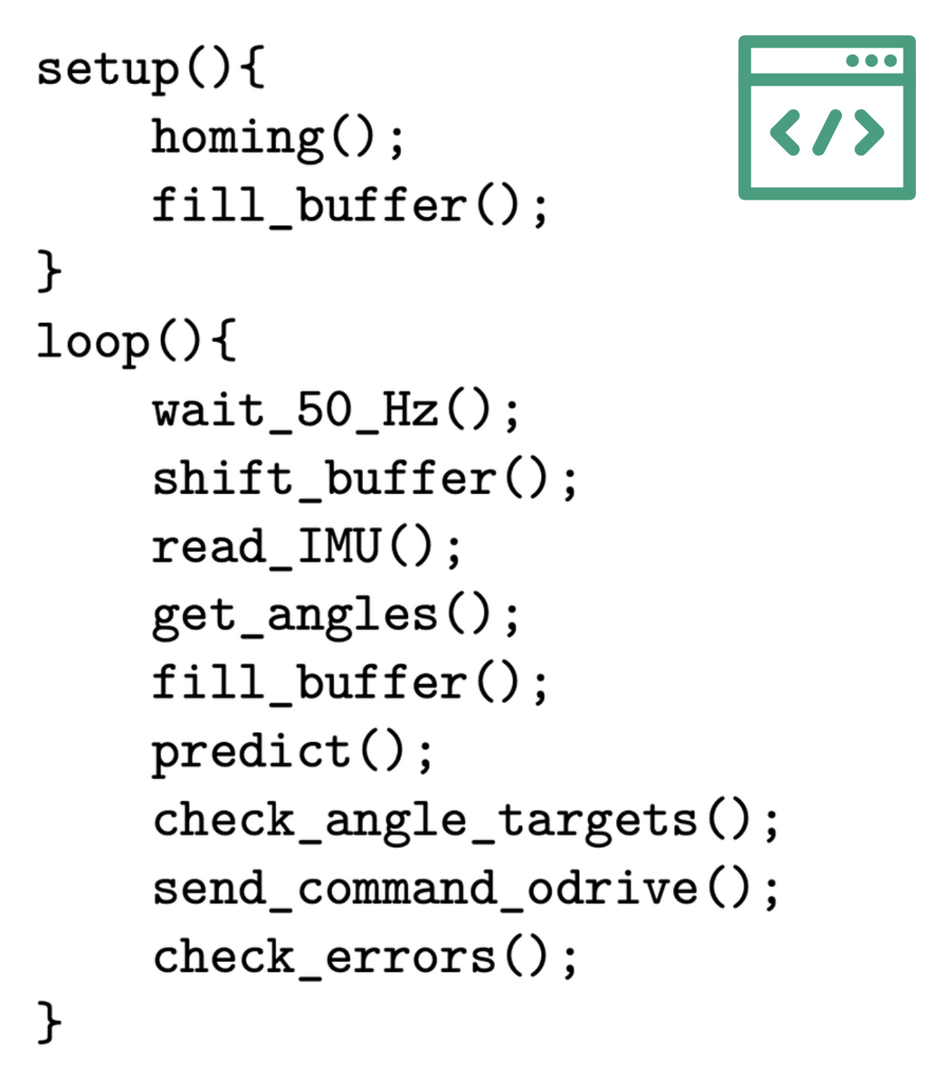
As the used encoders are relative, a homing procedure is performed on boot up. The procedure puts the Odrive on torque control mode and drives the joints toward physical end stops, when the system detects the joints aren't moving any more, it assumes the joints are at their hard limits, and therefore knows the position because it is defined by design. You'll find a hyper lapse of this procedure.
A buffer with 400 positions is filled for the first time, using real IMU data and joint positions. The wait_50_hz() function halts the loop if necessary to respect the 50Hz running frequency. Shift_buffer() shifts the 400-value buffer 8 positions to the left, discarding the oldest data and making way for the most recent values, it is a FIFO buffer. Read_IMU() is pretty self explanatory. Get_angles() uses the motor position and a forward kinematics model to estimate the current joint positions. The fill_buffer() adds the latest data to the buffer (six values from IMU and two from joint angles). Predict() requests a prediction from the neural network. Check_angle_targets() checks that the neural network predictions are within software defined limits. Send_command_odrive() sends the desired target position of each joint to the Odrive using the ASCII protocol. Check_errors() checks communication with the Odrive is active.
Static tests
With a ready to use prosthesis and some preliminary control algorithms, it is time to test the behavior. A few static tests enabled review of the behavior before proceeding to a much riskier user trial.
This is just a video of me moving the IMU and observing the prosthesis response.
Discussions
Become a Hackaday.io Member
Create an account to leave a comment. Already have an account? Log In.