 Mrinnovative
ESP01-Wifi-Shield-for-IOT-projects
The ESP8266 ESP-01 is a Wi-Fi module that allows microcontrollers access to a Wi-Fi network.
This module is a self-contained SOC (System On a Chip) that doesn’t necessarily need a microcontroller to manipulate inputs and outputs as you would normally do with an Arduino, for example, because the ESP-01 acts as a small computer. Depending on the version of the ESP8266,
it is possible to have up to 9 GPIOs (General Purpose Input Output). Thus, we can give a microcontroller internet access like the Wi-Fi shield does to the Arduino, or we can simply program the ESP8266 to not only have access to a Wi-Fi network, but to act as a microcontroller as well.
This makes the ESP8266 very versatile, and it can save you some money and space in your projects.

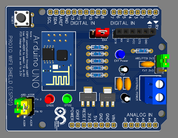
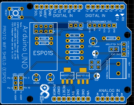
The ESP-01 WiFi Module Shield provides a convenient connection between an Arduino and an ESP-01 module, which contains an ESP8266 microcontroller with WiFi support.
The shield provides a 3.3V power supply for the module, and logic level converters so it can operate with either 3.3V or 5V Arduino boards.
- The Shield ESP-01 can be used for two purposes
Teaching Internet of Things with ESP8266 ESP-01;
Develop automation solutions with IoT and ESP8266 ESP-01.
PCB Devlopment


complete detail of the shield you can find here :- https://oshwlab.com/ctbully/wifi-shield-prototype
If you plan to order this PCB you can consider JLCPCB.com because
I always prefer JLCPCB.com for my PCB needs, JLCPCB.com have best deals for their customers $2 for 1-4 Layer PCBs, free SMT assembly monthly.
If you seriously need quality PCB quickly in your hand then you must have to try JLCPCB PCB manufacturing service. They have Special offer of $2 for 1-4 Layer PCBs, free SMT assembly monthly. If new user signup today from this link JLCPCB.com you will get welcome coupons from JLCPCB.
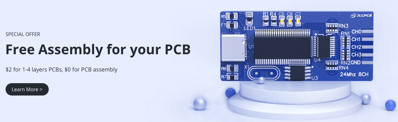
SMT Assembly service of JLCPCB.com is cherry on top now get your PCB fully assembled and save your time and money Select components for your PCB from there Parts Library of 200k+ in-stock components they are offering $30 valued New User coupons & $24 SMT coupons every month $8.00 setup fee, and $0.0017 per joint
Now no need to order components separately for you PCB and get free from stress of soldering them on PCB just try PCB SMT assembly service and get you PCB with components pre assembled and ready for the project
👉 Try PCBA service of JLCPCB.com and save your time and money, get PCB ready for project, 200K+ components in library of JLCPCB.com as well as 3rd party parts to choose from. Assembly will support 10M+ parts from Digikey, mouser
👉 $30 valued New User coupons
👉 $24 SMT coupons every month
For more detials & offers please visit JLCPCB.com
Hardware Setup
- Mount the shield on your Arduino.
- Mount your ESP-01 module on the shield using the header provided. The module must be oriented to align with the marking on the shield.
- Configure the serial jumpers near the top right of the shield to suit the pins your Arduino will use for communication with the ESP-01 module. The module ships with jumpers in a default position as shown above to connect the module's TX line to Arduino pin D2, and the module's RX line to Arduino pin D3. This means your Arduino will need to transmit on D3 (to the module's RX line) and receive on D2 from the module's TX line.
- Configure the reset jumper to connect module reset to Arduino reset. With the jumper in place (labelled "RST-LNK" on the PCB) the module's reset line is connected to the Arduino reset line, so when you press the Arduino RESET button your module will also be reset. This is a good way to ensure the module always starts in a known state when your Arduino resets. However, if you wish to isolate your module from Arduino reset you can remove the RST-LNK jumper. The jumper is fitted by default.
Software Setup
The software required to use your ESP-01 depends on the firmware it has installed. The most common firmware shipped on the modules provides a WiFi bridge that can be controlled via "AT" serial commands from your Arduino. You can therefore use your Arduino as a "serial reflector" to pass commands and responses between your computer and the module, allowing you to type commands in the Arduino IDE serial console and see how the module replies.
If your ESP-01 module has different firmware installed it may operate totally differently, and these instructions won't apply.
If your ESP-01 module is running the default firmware, open the Arduino IDE, create a new sketch, and paste in the following code:
/** * SerialReflector */
#include <SoftwareSerial.h>

SoftwareSerial device(2,3); // Rx, Tx

void setup() {  Serial.begin(115200); // Serial port for connection to host     device.begin(115200); // Serial port for connection to serial device } void loop() {   if(device.available())   {     Serial.write(device.read());   }   if(Serial.available())   {     device.write(Serial.read());   } }
This sketch opens a serial connection to your computer via USB at 115200bps, and also opens a software serial connection to the ESP-01 module via pins D2 and D3. Any data sent to one serial port is then retransmitted to the other port, allowing messages to pass transparently through your Arduino between your computer and the module.
In the Arduino IDE, select "Tools -> Serial Monitor" to open the serial monitor, and check that the speed is set to 115200bps in the bottom right corner. Also make sure the line-ending dropdown says "Both NL & CR".
Type "AT+RST" and press ENTER. This tells the ESP-01 module to restart. After startup the default firmware will output information about its version, then say "ready".
You can now send AT commands to your ESP-01 module and see the responses.
Reflashing ESP-01 Firmware
The default firmware installed on ESP-01 modules implements a serial-to-WiFi bridge that can be controlled using AT commands.
To install new firmware, the ESP-01 must be rebooted into a special mode that allows it to accept a new firmware image via its serial interface. This is done by pulling the GPIO0 pin LOW (0V) while the module is starting up.
sing a jumper wire, make a temporary connection between one of the GND pads on the shield, and the GPIO0 breakout just to the right of the prototyping area. Press RESET, and your module will now reboot into flashing mode.
Conclusion
This board is a great solution for:
Who wants to have their own shield to record the ESP8266 ESP-01;
Who wants a board to develop automation systems for the internet of things;
Teachers or students who need a didactic board for learning and teaching IoT.
This circuit board is very simple and easy to assemble. Take advantage now and get 5 free samples to build automation projects with the internet of things.
- Follow the step to get this shield board.
1 - Download the circuit board Gerber file: https://oshwlab.com/ctbully/wifi-shield-prototype
2 - Create an account using the link below: JLCPCB.com
3 - visit JLCPCB.com Add the Gerber file and place the order.