 Mrinnovative
BC547-based-liquid-level-Indicator-with-custom-PCB

How to make a water level indicator to save water from overflowing with Motor Dry run prevention.
A water level indicator is used to show the level of water in an over head tank. This keeps the user informed about the water level at all times and avoids the situation of water running out when it is most needed.
There are so many tutorials on net But this one is unique because this water level indicator circuit also has an water flow signal.
It not only indicates the amount of water present in the overhead tank but also gives the water inlet signal so that dry run can be prevented.
COMPONENT REQUIRED
- Transistor BC547 -- 4 no's
- Led's - 4 no's
- Resistor 330 ohm - 4 no's
- Small PCB
- 9V Battery with Clip - 1 no
- Female connector - 1 no
7.Some Wires.
Basically the unit is made up of various sensors acting as a switch. Let me explain in a simple way. What happens is when you turn on you water pump, the water starts to get pumped from your underground reservoir or from your underground water supply from the pipes to your water tank. In the tank there is a set of sensors( to be precise there are 7 sensors), in the water tank. Just think them as a switch,
as the work of the sensor will be to connect a circuit. I will explain in details. So the water starts to get filled in the tank and when the water level in the tank starts to rise up, what happens is that the sensors that is installed in the tank
starts to get activated one by one indicating the water level in the tank. And finally when it reaches to its top most sensor, there will be a visual display as well as a sound from the unit indicating that the water has filled in the tank and one can be alerted that the tank has been filled up and the water pump has to be switched off saving the electricity bill as well as over flow of water from the tank.
CIRCUIT DIAGRAM

It has numerous transistors acting as a switch and the switch gets activated when the sensors tell them to.
The heart of the circuit is the transistors BC 547. There are total 4 transistors in the circuit and each one will be sensing the level of water present in the overhead water tank. There is one extra power LED without a transistor and that is because this Red LED will be telling us two things. Firstly when you power the unit it will be monitoring the power present in the unit and secondly it is also the indicator telling you
that there is no water at all present in the tank. As because the water level is below the No. 1 (as shown in the circuit) sensor, no LED's will be lighting up, but only for the one Red LED. Therefore when you switch on your unit if you see only one Red LED lighting up then you know that the is no water present in the tank and therefore you should make you water pump on.
Then as shown in the figure i have given all the LED's in various color. Starting from the beginning is Red LED - 1 (Indicating no water in the tank as none of the sensors are getting contact with the water) Red LED - 2 ( Level 1, indication very low water in the tank ) Red LED - 3 (Level 2, indication of half water level) Red LED - 4 (Level 3, indication full water)
Now as the water starts to rise up the sensors starts to get in contact with the water and the transistors are activated and there is a flow of current in the transistors making the LED's light up. Here in between the transistor and the LED there is a current limiting resistor 470 ohms,
the job of the resistor is to checks that the LED does not get over voltage and destroy the LED. The transistor is biased by a 470K resistor with the ground and the sensing part is taken from the collector with a 33 ohms resistor going directly to the tank. As i have shown in the diagram the signals are drawn in the Green color.
There by you can follow the LED's as they light up from Red to Yellow and then Green and finally to Blue making a sound.
Before moving further I would like to tell...
Read more »
 Electroniclovers123
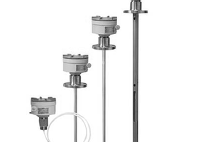
 mbsg99
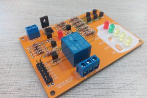
 ElectronicABC
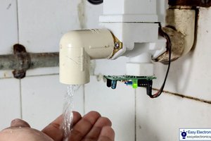
 Subhajit