 adriancubas
From the beginning of this Project I always wanted to store the energy captured in lithium batteries, preferably in 18650 type cells. I consider that these cells are a proven technology, with a high energy density, with a high level of safety, accessible and with a not so high price.
NP-F batteries in their different configurations (330,550,750,970 etc…) have this type of cells inside in a 2S configuration, that is, two cells connected in series. In a previous Log, where the electrical characteristics of the generator were addressed, it was concluded that a 2S configuration with a voltage range of 6V-8.4V is recommended as a storage system and this type of battery has this configuration.
As a reference let's take the Samsung INR18650-25C, its technical data sheet can be consulted here: https://www.powerstream.com/p/INR18650-25R-datasheet.pdf
This type of cells can support a maximum of 4A of recharging current for each cell, this is a higher value than that delivered by the generator of our Portable Wind Turbine. We can extract from them a maximum of 20A of discharge current continuously. They have a capacity of 2450mAh, when discharged at a rate of 10A. After 250 charge and discharge cycles they offer only a 2Wh decrease in capacity from the initial 7.4Wh (4A charge current up to 4.2V and 20A discharge current down to 2.5V). At -20 degrees Celsius and a cycle of 10 A of discharge current and 4 A recharge current, they retain 96 percent of their original capacity.
I don't think that all NP-F battery manufacturers use this type of Samsung cells, although I think that the characteristics of the ones they use should be similar in several respects.
Also, NP-F batteries have a BMS circuit inside them that adds safety and protection functions to the cells. I took the job to disassemble one of these to see its internal structure and analyze its characteristics. Specifically, it was an NP-F970 with a charging circuit and USB output https://amzn.to/3SsQVih *affiliate link*
In the previous photo you can see that this battery is made up of (6)) 18650 cells in 2S3P configuration. The circuit that can be seen above these cells is a BMS (Battery Management System) and the one that can be seen below is the charging circuit, charge level indicator and USB output. You can charge this type of battery with a charger specialized in NP-F batteries or simply through a micro USB connector. You can also power your compatible USB devices directly from this battery.
These batteries also come encapsulated in a plastic case that, while I don't necessarily consider it waterproof, I do consider dust and splash resistant. If any of you know if there is any IP-X certification for this type of battery, could you tell me where to find it?
One of the main functions of the BMS is to prevent overcharging and overdischarging. In addition, these circuits protect against short circuits, limit the maximum charge and discharge current. To test these features, I ran several experiments trying to find answers to the following questions:
- Does this battery have short circuit protection?
- What is the maximum charging current supported?
- What is the maximum load current supported?
- What is the maximum voltage that the BMS allows to the cells?
- What is the minimum voltage that the BMS allows to the cells?
The battery has short circuit protection.
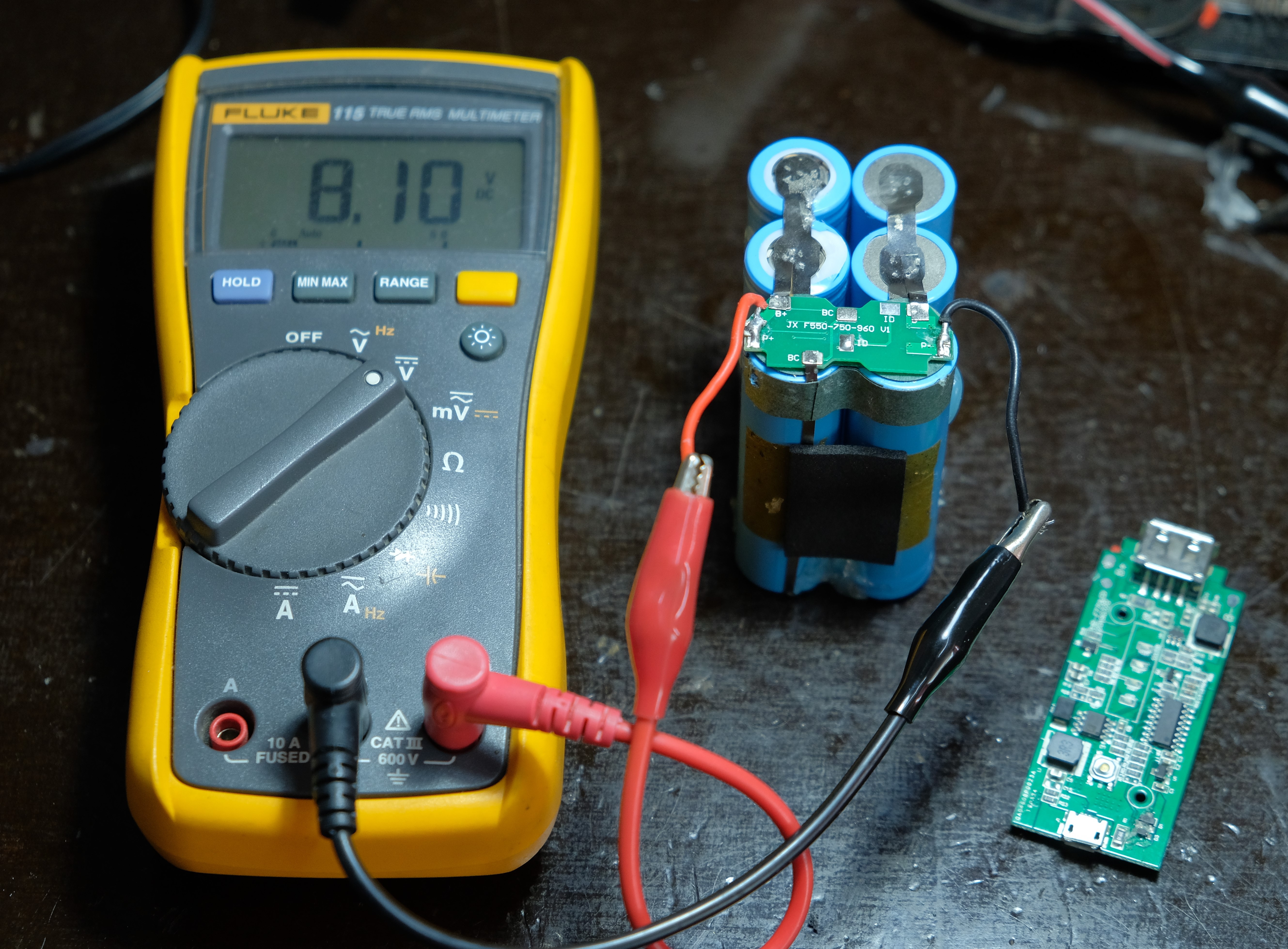
The maximum charging current supported in my experiments was around 4.75A as can be seen in the video. For this, a variable current source was used and the current value was increased until the BMS circuit interrupted the charging process. The experiment was repeated several times and the results were consistent.
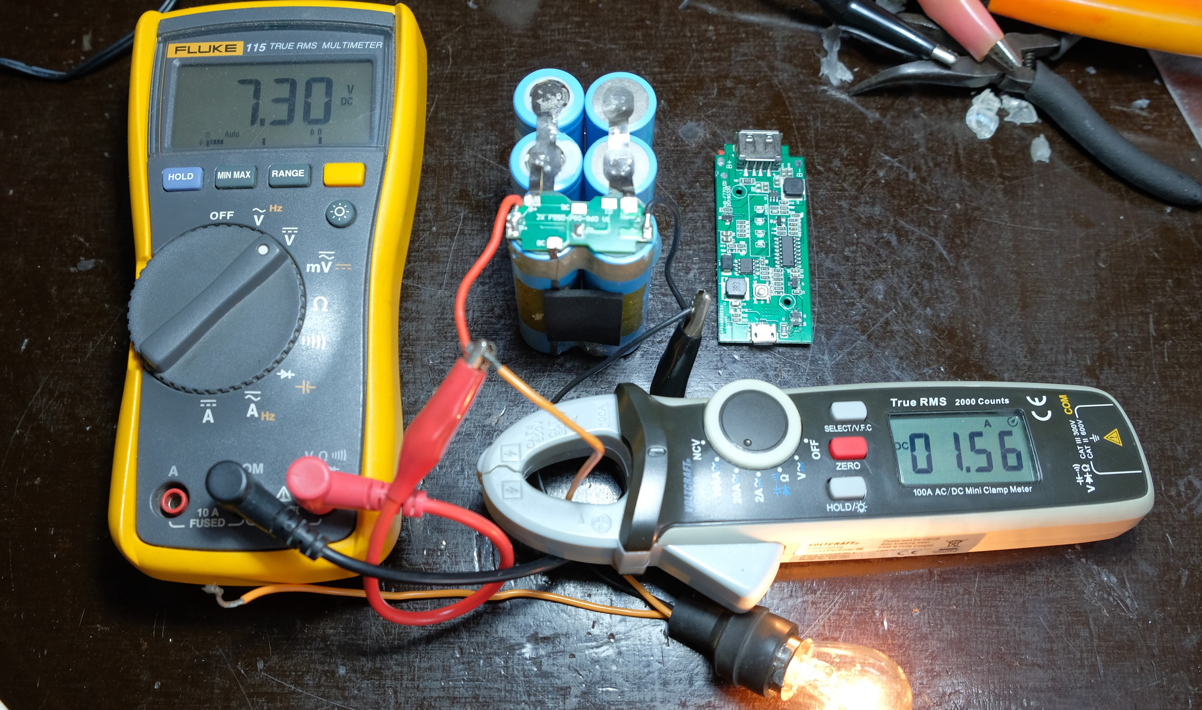
To check the maximum discharge current a Load Tester was used like this https://amzn.to/3yd4HNM *affiliate link*
This battery exceeds the 5A discharge current of this module, triggering its overcurrent protections. I tried to use a 55W car bulb and the BMS trips the overcurrent protection. I managed to get the battery to operate at 4.5A continuously with no problems.
Using a variable current source set to deliver a maximum of 1.85A, it was possible to determine that the BMS cuts off the charging process once 8.62V is reached, or approximately 4.3V per cell, which is a bit high for my taste, I would have preferred about 4.15V to promote greater longevity of these cells. In the video you can see this.
In the case of the minimum voltage that the BMS allows, this is 4.7V, about 2.35V per cell, also very low.
I think this manufacturer here has tried to maximize the capacity value over the longevity of this battery.
To conclude, I wish to express that this type of battery is offered as compatible and convenient for the characteristics of our Portable Wind Turbine Winturer-P4.
In the next Log I will be presenting the completed design of Winturer-P4 and the design decisions made in correspondence with the results expressed in these logs.
Thank you for following these developments. See you!
Discussions
Become a Hackaday.io Member
Create an account to leave a comment. Already have an account? Log In.