 adriancubas
Hi everyone,
One of the main problems that you may face when using this Wind Turbine is that it cannot overcome the impedance of the Battery to charge it. If in your area the winds do not blow so fast, if you have used the generator as it comes standard without rewinding it and in turn you have not used a Schottky diode rectifier, it is likely that the voltage obtained is low.
To recharge a 7.4V nominal voltage battery (NP-F standard), it is necessary to apply a voltage higher than this at its terminals.
I came up with an idea that could help many of you. What happens if we use a battery that requires a lower voltage to recharge?
Here's my 3.7V nominal voltage version of a battery that looks like a standard NP-F. Also, this battery is 100% compatible with WINTURER-P4. So, if you already created your version of this Wind Turbine, you don't need to change anything.
Another aspect to highlight is that it can be created from 18650 cells recovered from disused laptop batteries, power tools, etc... With this we are recycling and giving a new use to these batteries that would otherwise end up in the trash.
Affiliate links appear in the following list
For this battery you may need the following items:
• 18650 lithium batteries ( https://amzn.to/3iUcL1b )
• BMS 3V-4.2V ( https://amzn.to/3FojfNC )
• DC power supply socket female panel mount connector ( https://amzn.to/3USBJLJ )
• Contact pins ( https://amzn.to/3HxX1Lt )
• Power bank PCB module board ( https://amzn.to/3PpWNbp )
• 2.1 mm male barrel connector ( https://amzn.to/3WboOWi )
ASSEMBLY INSTRUCTIONS:
Download the STL and print them in ASA or PETG filament. The files were attached in the FILES section of this Project.
In my case I did not use supports to print the pieces and I set the layer height to 0.2mm. Follow the filament manufacturer's recommendations for a successful print.
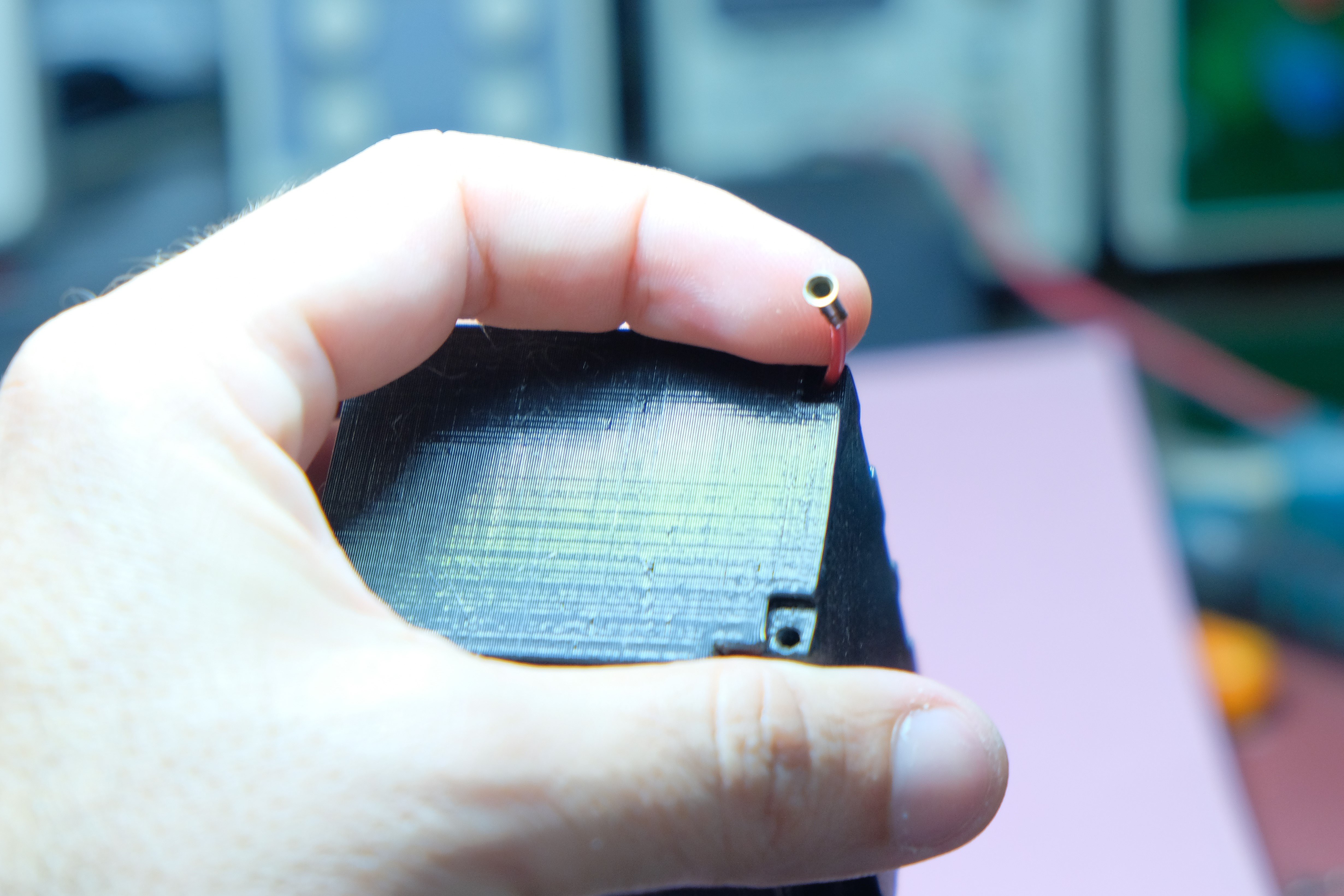
Solder 2 different colored lengths of wire to two 2mm female connectors
Drill two inside holes so you can get the wires inside the battery case.
Apply some epoxy glue and insert the female pins (you may have to shorten them to fit into their positions)
Solder the above wires to the P- and P+ pads of the BMS. Be careful! The polarity of the connections must match that obtained on the generator.
Check with a voltmeter that all the batteries have a similar voltage. If there is one with a very different voltage you should not use it.
Join the 4 Batteries and tin each other their positive and negative parts. Watch out! You should not join the positive and negative poles of the batteries together because you will cause a dangerous short circuit.
Solder the Positive part of the Batteries to the BMS on the Pad marked with B+ and the Negative part to B-
The Pads P- and P+ are also soldered to the DC connector respecting the polarity (the central part of the connector is positive and the outer part is negative).
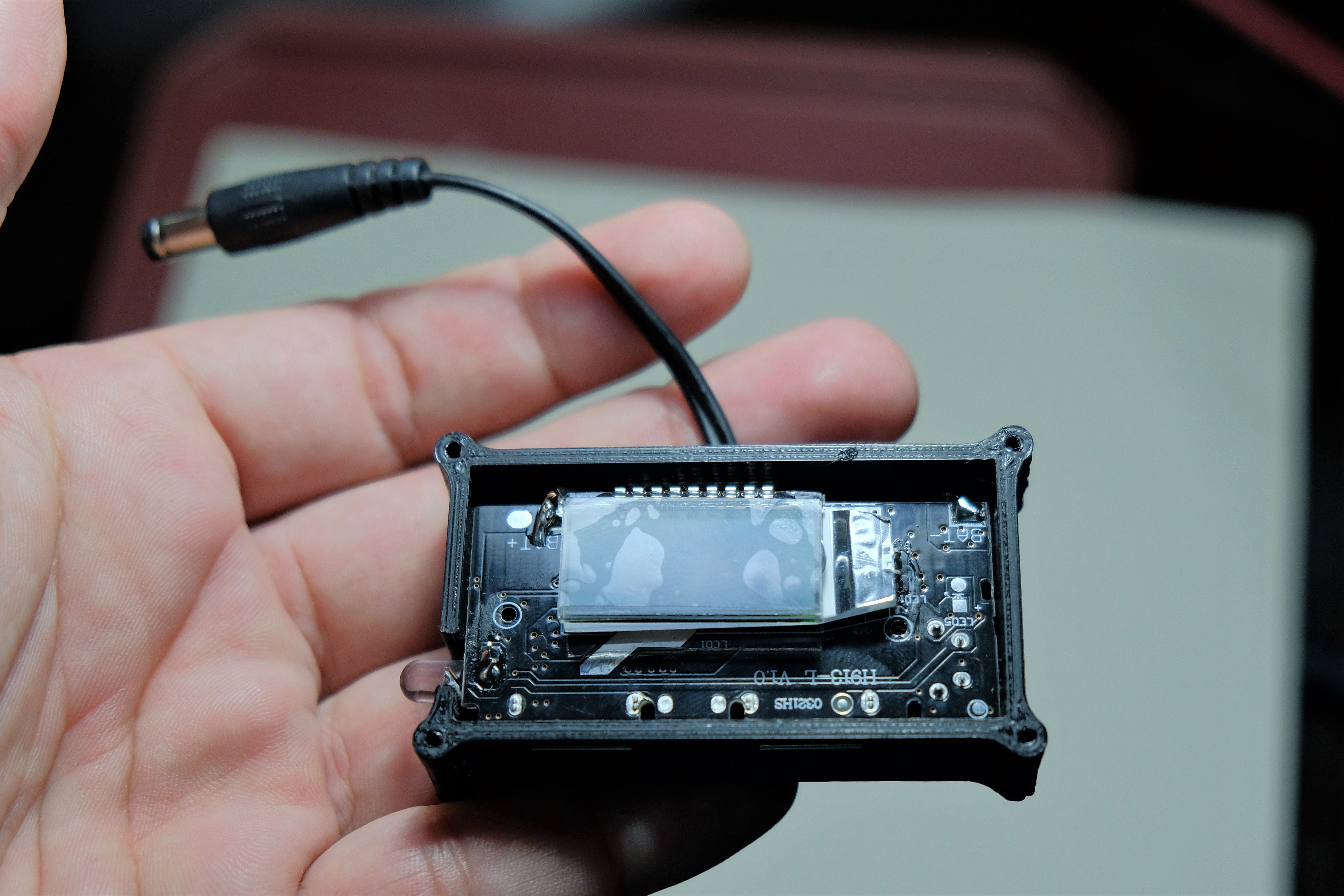
Solder the 2.1mm pigtail to the + and - connections of the Power Bank PCB Module Board. Observe the required polarity. This module does not have reverse polarity protection and will be damaged if this occurs.
Place the Power Bank module in its case and cover it with 4 x 2.5mm screws.
HOW TO USE THIS BATTERY
Put the battery in the WINDTURER-P4 and capture energy from the wind. There is no danger of damaging the 18650 cells by overvoltage etc., since the BMS will manage the cells so that this does not happen.
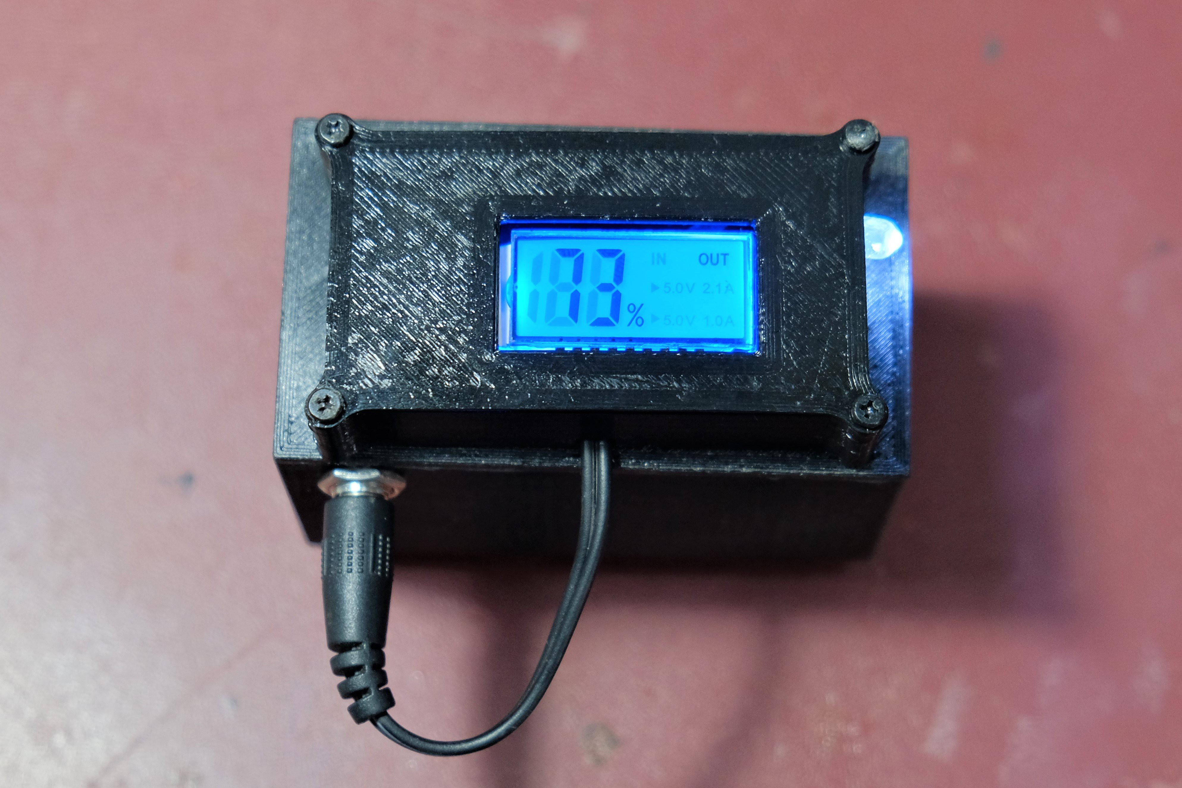
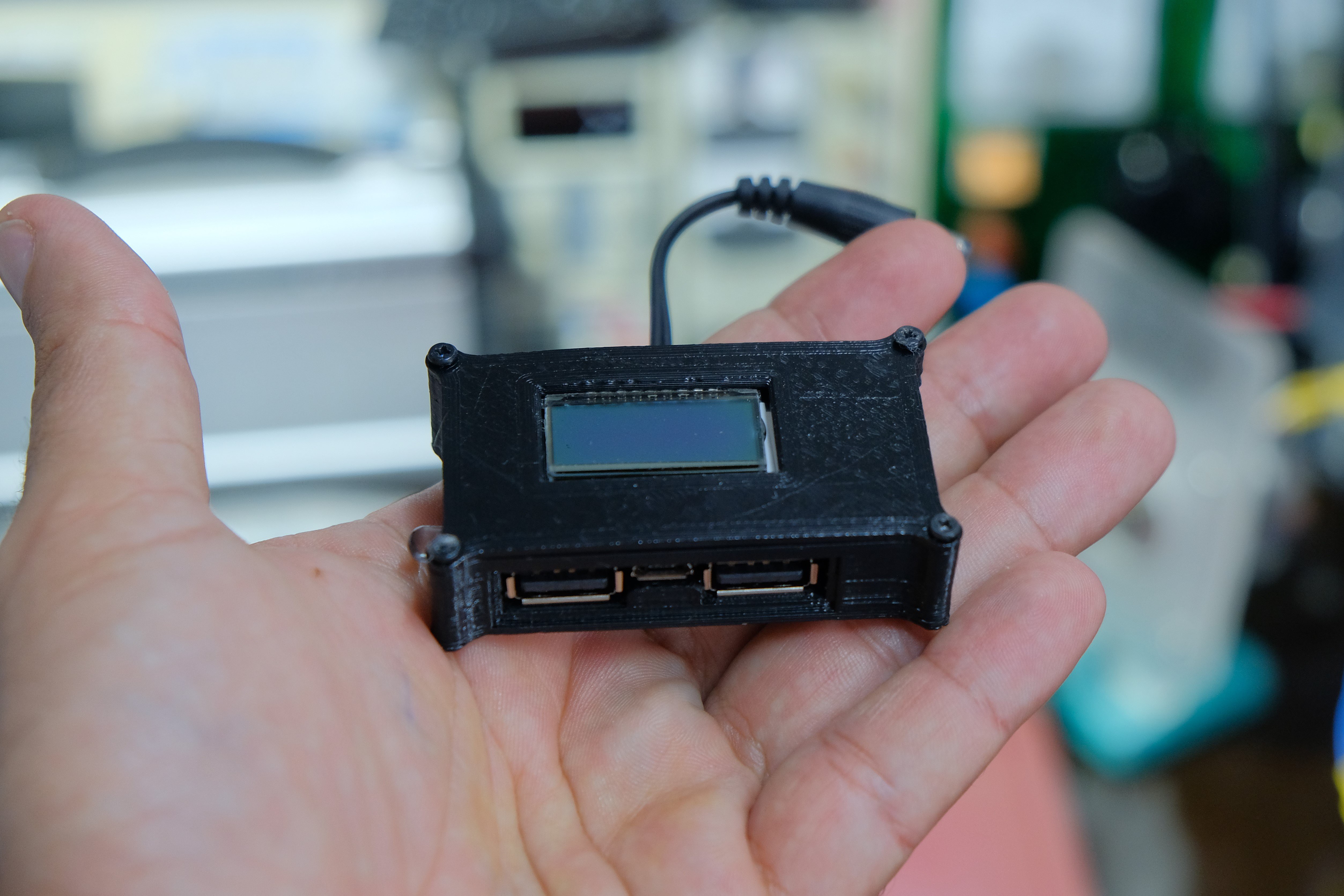
When you need to use the energy captured in the battery, remove the Battery from the WINDTURER and connect the BMS module. Press the side button twice until the side LED turns on, then press once to turn it off.
The lcd panel will display an estimate of the battery charge. Connect any USB device to its ports to provide them with the power they need.
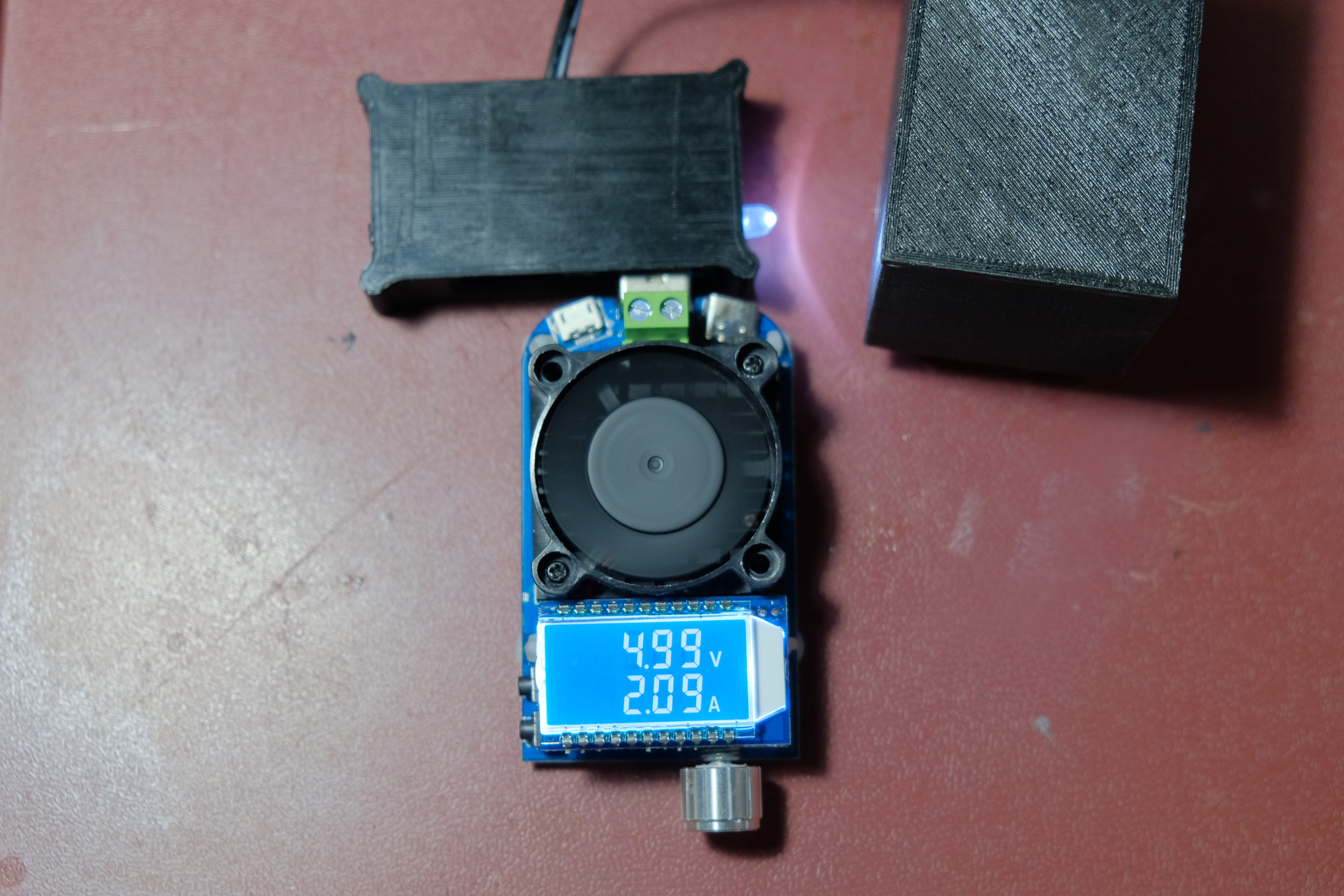
These Power Bank modules can handle currents of even slightly higher 2A.
Note: Never leave the PowerBank module connected to the battery while it is charging in the WINDTURER. If the battery completes its charge and the BMS stops the recharging process, a voltage higher than the allowed one could completely destroy the PowerBank module.
Additionally, if you connect a 5V Micro USB cable to the Power Bank module, you can charge the battery with power from the mains.
In this case 18650 cells were used but using a similar procedure, you can fill this casing with batteries of another type such as NiMH, LiFePO4, etc. even with lower charging voltages. There are many transformations that you could make depending on your needs and objectives. Thanks for following me here.
Best
Discussions
Become a Hackaday.io Member
Create an account to leave a comment. Already have an account? Log In.