 Wenting Zhang
This is my little research project to see how grayscale works on FSTN LCDs. I have made a video about what I learned:
The following is the transcript of the video for archiving purposes.
Hello everyone, Wenting here. What type of screen are you currently using to watch this video? I guess many people would say it’s a TFT LCD, be it TN VA or IPS, and some other would probably say AMOLED, which is also quite common nowadays. These display technologies have been a critical part of the mobile devices we use today. However, before any of these dominated portable devices, there existed another type of screen technology, the passive matrix LCD. The reflective monochrome screens with a green-ish tint.
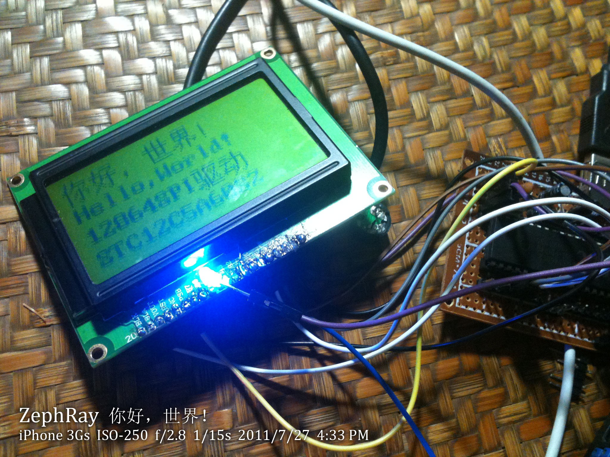
Many portable devices made late last century and early 2000s featured this type of display. While they are almost extinct on modern consumer electronic devices, they could still be easily found on various embedded devices. I am always fascinated by the distinct look of these screens. So I picked up a few of these screens online, and started learning microcontrollers to drive them.
That was more than 10 years ago.
To clarify, generally there are 2 types of screen interfaces, the video/ pixel interface and the MCU/ MPU interface. Pixel interface would only take pixels, and works like a video stream, with continuous pixel transmission and horizontal vertical sync signals, sort of like VGA. MPU interface is kind of like a coprocessor interface, the screen has its own memory, and the host sends commands to the screen, over some general purpose bus protocol like SPI, I2C, etc.
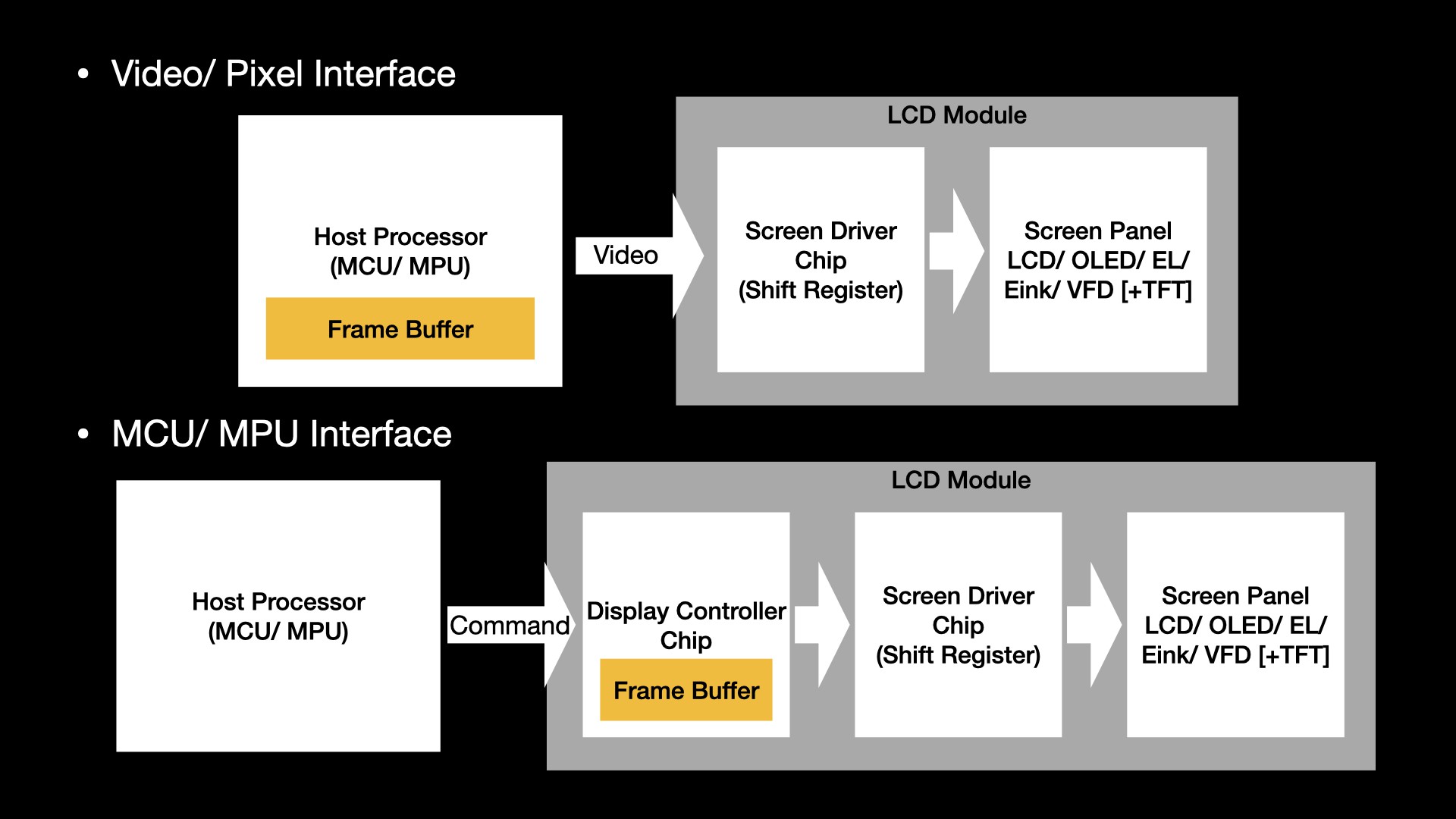
One major difference is then who would be refreshing the screen. LCDs typically need constant refreshing to keep the image display. If using a pixel interface, then the image is streamed directly into the screen scanning circuit and driving the panel. If using an MPU interface, then the image data is being written into the screen’s controller memory, the controller would then refresh the screen asynchronously.
Generally, for these monochrome screens, screens with resolution equal to or higher than 240x160 tend to use pixel interface, and for color TFTs, screens with resolution equal to or higher than 640x480 tend to use the pixel interface over MPU interface. The same division exists for eink panels as well. These resolutions are just for reference only based on my personal experience, please refer to the datasheet for the interface used on your screen. The advantage of using a pixel interface is that the screen output is synchronized to the host, so things like tearing could be easily avoided, but the downside is that the host must be fast enough to push the pixels at screen refresh rate, and typically needs to have large enough memory to hold the entire frame buffer. MPU screens, on the other hand, don't require these, but getting a tearing free image on these could be tricky. In this video I am going to focus on screens with pixel interfaces.
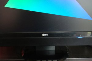
Back to our topic, this is a 320 by 100 pixel reflective FSTN LCD screen, with de-facto industrial standard STN LCD pixel interface. I don’t know the name of this protocol, but I can confirm the same protocol is used across many many many different pixel interface STN screens. Which is really just horizontal sync + vertical sync + pixel clock + inversion clock, with a bunch of data lines, transmitting multiple pixels per clock.
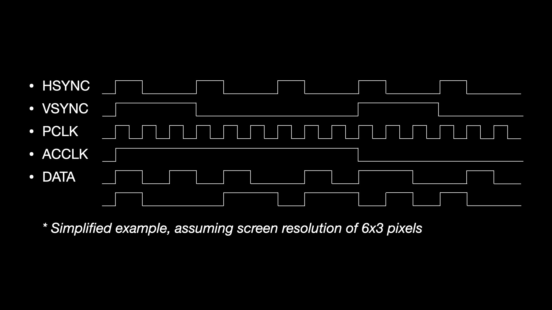
I am not going into details about this protocol though. If you are interested, it is the same protocol as the EL screen one I showed in the previous video, and you can find more detailed info there. In summary, the microcontroller sends the entire frame to the screen at a constant refresh rate of 60 to 120 Hz.
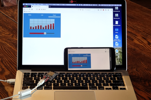
So let’s display some images on it.

This is the source image, and this is the… result.
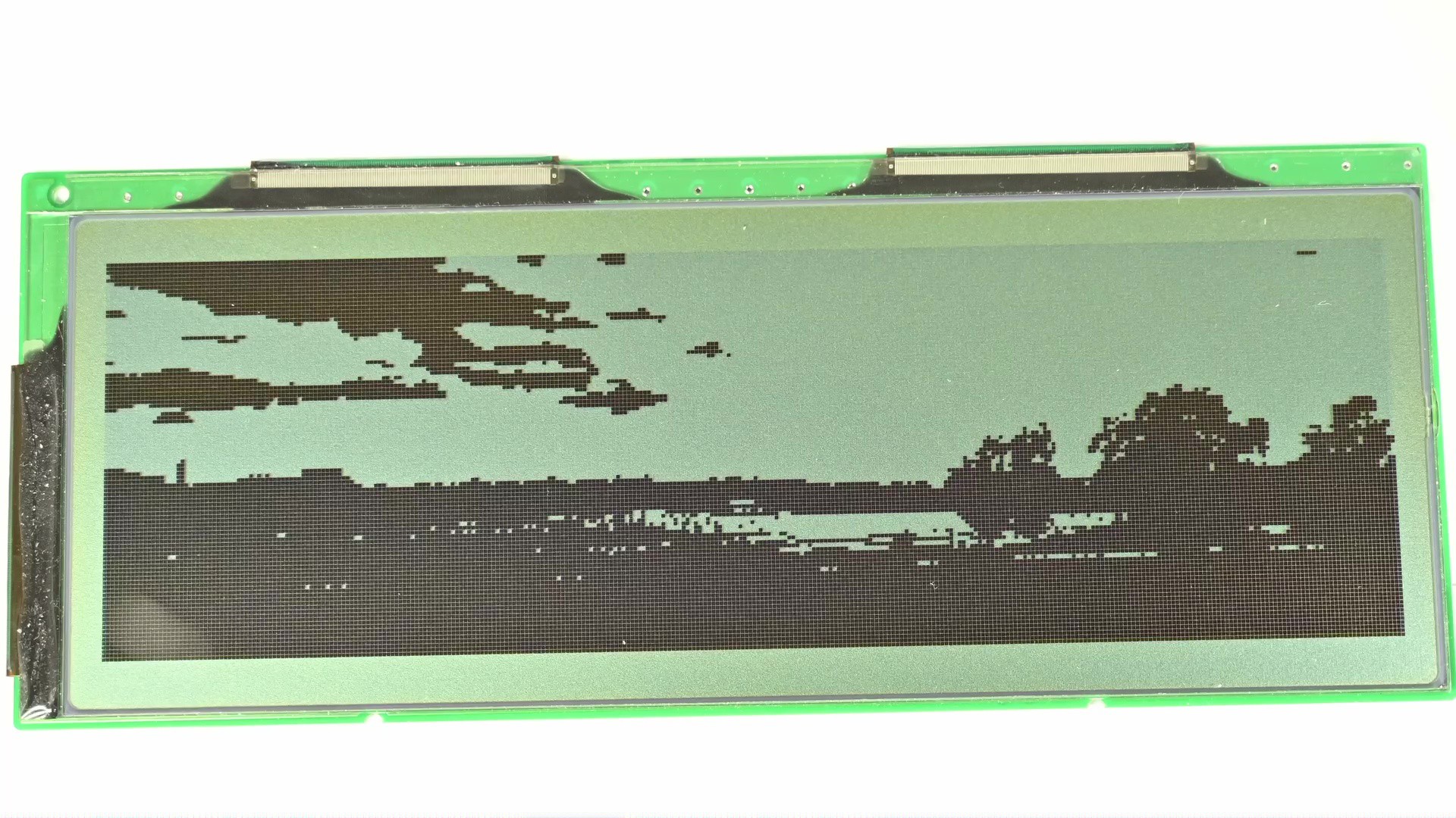
The issue is obvious, the screen is 1-bit monochrome, so for each pixel it could only be either on or off, without any gray shades in between. If I just directly display the...
Read more »
 Dan Julio
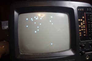
 Mars
Mars