 JP Gleyzes
Since the very beginning of this project in may, things have evolved a lot. I am now extremely honored to be one of the finalists of Hackaday Prize 2022.
Consequently the project has followed its own track and is now significantly "bigger" than in spring!
My advice, not to be lost into the various pages and logs, would be to read the whole description (this long page!) and then jump into the logs.
Alternatively here is a Table of Content that you can follow to directly access specific topic into logs.
Table of Content
building the frame
building the Solar Tracker
- mechanics
- electronics
- pcb
- calibrating the solar tracker (version with worm gear on Azimut axis)
- equations of motion (version with worm gear on Azimut axis)
- firmware lite version
- Android App panel orientation lite version (version with worm gear on Azimut axis)
- Automating the Solar tracker initialization (version with worm gear on Azimut axis)
- V2 source code for firmware and Android panel Orientation App
- a fully new Azimut axis mechanics
- new Azimut: equations of motion
- a new auto calibration procedure (version with linear actuator on Azimut axis)
- publishing v3 source code for firmware and android app (version with linear actuator on Azimut axis + 4 hours timelapse video)
building the MPPT Controller
adding power storage
using the system
going further
The true story
I started this project after buying this 100W flexible solar panel during BlackFriday last october.
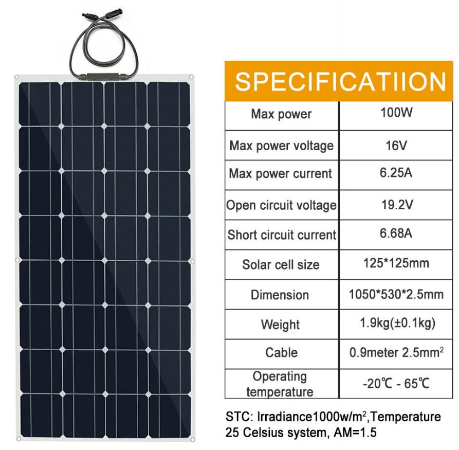
These panels are quite cheap and are very light (less than 2kg). They are thus well positioned to design a portable system.
Here in Europe it was the beginning of the winter season and I very soon discovered that a solar panel rated at 100W never produces such a power in winter times...
So I started to imagine a system to harvest the most possible power from this solar panel while preserving two main objectives that I fixed to myself :
- keep it as cheap as possible (as it was for me a hobby and a way to discover real problems with PV panels before thinking to equip my house with a Pro installation)
- keep it portable, ready to go, easy to operate and light (I wanted to be able to carry this panel in the fields to recharge my Parrot Disco flying wing batteries or to use it in a camper van !)
Finally, to be honest, this project wasn't intended to participate to the Hackaday's contest.... But when I received the reminder mail (two days before the deadline) and read the objectives of this contest... I frankly believed that with no effort I was completly inline with the Planet-Friendly Power themes :
"Build a hardware solution that lowers the cost of clean energy, through energy harvesting and/or storage efficiency improvements."
In the following sections I will cover the design of
- the frame for the PV panel
- the solar tracker system
- the MPPT controller
- adding battery pack
And you will soon see how my design lowers the costs while improving efficiency of energy harvesting with solar panels !
Everything wil be open source either hardware or software, so you will be able to build your own whenever you want !
Currently (may 22) I do have a working prototype, but even if a lot has already been done, there is still a lot of job to clean the code and to improve the operations. Stay tuned !
The frame
Adding a frame to a flexible panel was an absolute necessity !
Furthermore this frame should be "scalable" to be reused for the solar tracker system
I wanted the frame to be light and cheap, so I forgot using metal and jumped to a "full plastic" solution.
Considering the low cost approach I decided to build it around cheap 20mm PVC pipes used for electrical installation. You can purchase them at less than 1$ for 2m. You will need two of them to build the full frame
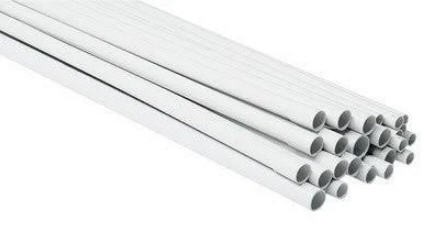
To assemble the frame I designed 3d printed corners and hinges.
They are already available for download on thingiverse on my account : tilting frame for PV panel
Simply insert the PVC pipes into the corners and screw all this to the PV panel using 6mm screws and washers !
Something that I would like to mention is that 3D printing is not "free" as the filament costs "a lot" !
In order to lower the price of the project and to keep the "reuse, recycle, revamp" spirit of the challenge round#2, I decided to use PET filament that I produced from plastic bottles.
So I can proudly consider that the 3D printed parts of this project are totally free (avoiding to take into account the electrical bill... considered as negligible)
This was just to tease a little, as I will for sure publish my "pulltruding machine" to the next contest
As you will see, printing with plastic bottle PET has also the advantage of strength and also it resists to very high temperature (printed at 265°C). This is important as the back of a solar panel can easily overheat at more than 60°C. So if you use PLA for parts in contact with the panel it may start to melt...
The solar tracker
Principle of operation
A solar tracker will help to follow the sun during the day and to point the panel strictly perpendicular to the sun rays.
So a "good" solar tracker must not only follow the vertical motion (elevation angle) but also follow the East/West motion of the sun during the day (azimuth angle). The structure should have two degrees of freedom : a horizontal rotation to set azimuth and vertical rotation for elevation.
Doing so should increase the solar production of electricity by a ratio of 30 to 40%.
It's a complex modelisation, but you can read this very interesting publication : performance of a Dual Axis Solar Tracker versus a Static Solar System
Results seems to vary greatly, from place to place, but are in the range 30 to 40% of gain for dual axis Solar Trackers.
I will not debate too much on the benefits of solar tracker, but if you are interested please have a look at this Britannica's paper. It also emphasizes the main drawback of these devices : reliability, cost and complexity...
My solar tracker is deliberately simple and relies only on :
- position of the solar panel : ie longitude and latitude of your device (this is a fixed parameter)
- time... (this varies all day long...)
With these variables known you can easily compute the solar position into the sky and point your panel accordingly.
The solar angles change during the day but also change from day to day... The sun being higher into the sky in june (summer solstice) and lower in december (winter solstice).
You can find on the internet a lot of clever sites explaining this and providing "sun charts" like this one

This being said it seems obvious that pointing to the sun will increase a lot your solar panel performance.
The mechanics
A solar tracker is classically a huge heavy device with strong motors and actuators... It is expensive and complex.
For my flexible panel with its light frame I have again tried a "light" approach for the mechanical part of the sun tracker.
"Light", as usual now, means :
- not heavy, as little metal as possible, as much plastic as possible
- cheap... mostly 3d printed (with zero cost plastic bottle PET filament) : files here on My Thingiverse account)
- minimal electronics, minimal power consumption, mininal motors
- portable and compact
But without sacrificing the reliability, nor the automation, nor the pointing accuracy, nor the ease of use
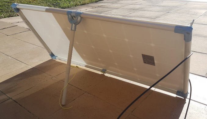
The mechanics has been designed so that most of the parts can be printed and assembled as described in the Mechanics log.
Here is the final result :
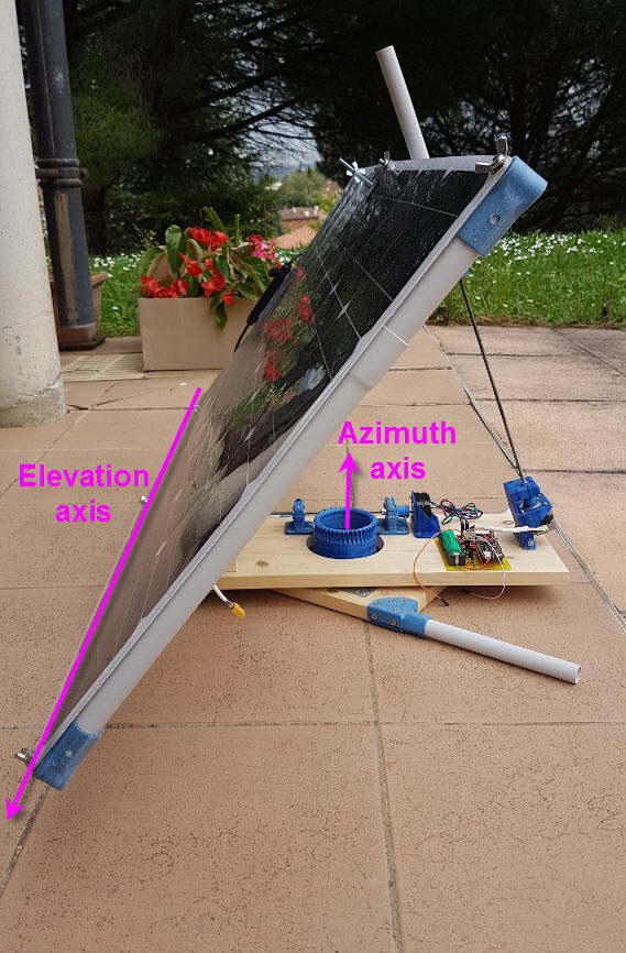
Rotations are thus done on the Elevation axis (bottom PVC pipe of the frame) and on the azimuth axis as shown.
Equations of motion are explained into this log.
The elevation rotation is performed via a linear actuator composed of a lead screw (5mm diam stainless steel 70cm long) which is activated by a NEMA17 stepper motor.
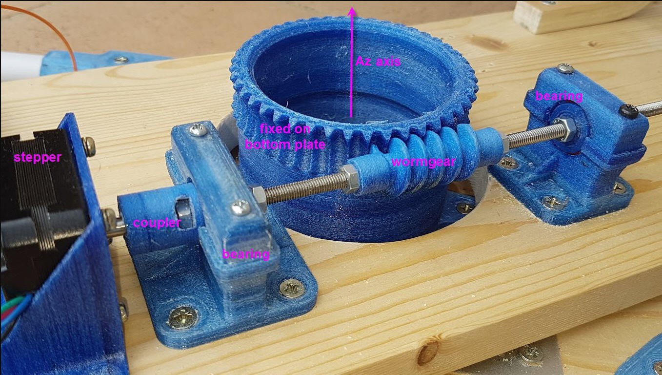
The Azimuth rotation is performed by a worm gear driven by another NEMA 17 stepper.
The big Az Axis gear is fixed on the bottom plate while the worm gear rotates on the top plate. Both plates are connected by a "lazy Susan" metal gear (turntable gear).
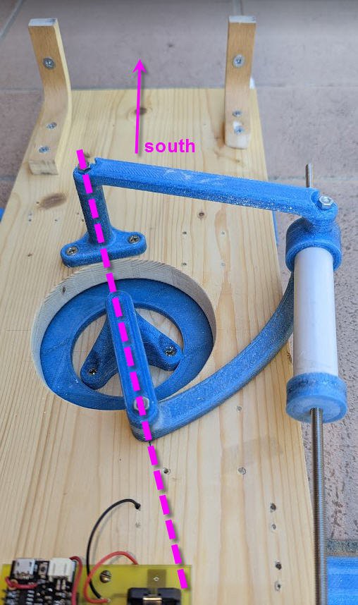
A newer azimut mechanics
A newer mechanics exists now offering a much better torque and a better precision. Although the "worm gear" option described above works quite well, I would highly recommand to build this newer version now!
Everything is explained into this log.
The mechanics and the cinematic are a little more complex to understand but it worths to study them!
And the final price will be the same (even cheaper as there will be one less roller bearing!)
The equations of motion of this new axis are a little more complex than with the worm gear mechanics. If you are interested into maths and trigonometry then have a look here.
I have implemented these formulae into the ESP32 and started validation tests...
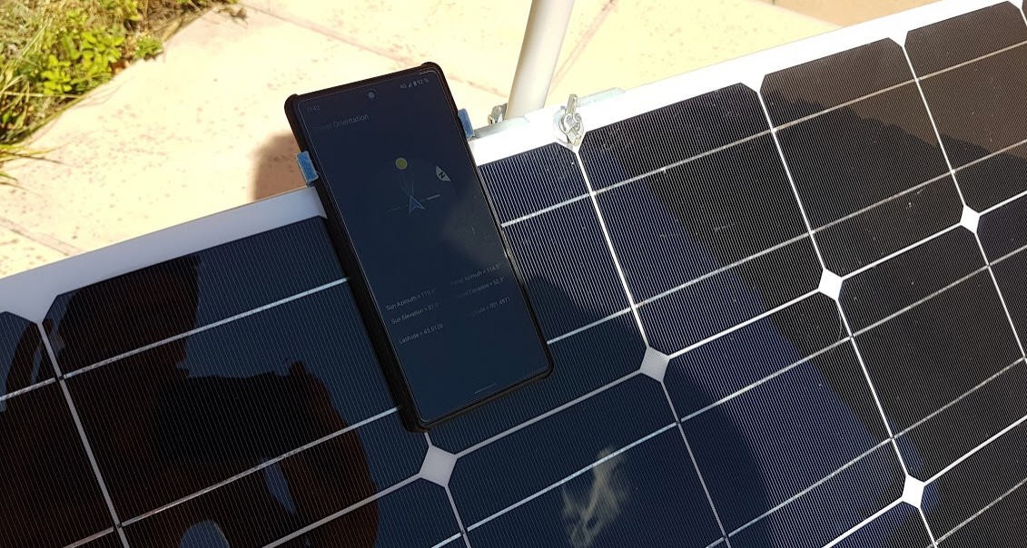
To keep the user friendly spirit I also implemented a new auto calibration procedure, both into the firmware and the android App.
Put the phone on the panel (as usual) press the "find sun" button and that's it!
I will of course publish the code very soon. Stay tuned!
The electronics
You can see on the picture a PCB including :
- a small 360 DC/DC step down converter powering 5V to the MCU
- a Lolin32 lite ESP32 board (G6EJD's review here)
- two easydrivers stepper motors boards
- a backup battery (single cell 18650 Li-ion bat (optional !)
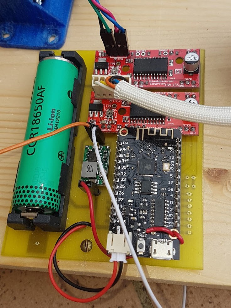
Refer to the electronics log for details.
The firmware
The ESP32 is programmed under Arduino IDE. The code is quite simple but provides the following functionalities :
- try to connect to internet
- get the UTC time over NTP server
- in case of failure open a bluetooth connection with an android App
- get the time over Bluetooth Low Energy
- in case of failure : use the RTC time
- compute the sun position using the excellent solar calculator library (licensed under the MIT License)
- compute the stepper motors motion
- read the power voltage
- perform the motion if the power level is enough to drive the motors
- apply a sleeping strategy (sleep 10 minutes during day or sleep the whole night)
- reset to the next morning position if needed
- sleep and wake up next time
And regarding the calibration of the Solar Tracker... I found this lazy but efficient way !
First release of the source code is here: ESP32 Solar Tracker
A companion Android App has now been pusblished to allow fast calibration of the panel and initializing location and time for the ESP32 board.
- launch this App,
- Align the panel
- press the reset button (to send time and position to the ESP32)
- quit the App
Simply put your phone on the panel, rotate it to face the sun, adjust the elevation angle (screw/unscrew the nut)
and push the reset button. A matter of seconds to setup your panel !
Source code for both the firmware and the Android App are available here (for V2) and here (for V3)
The MPPT controller
Theory of operation
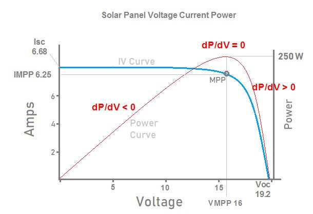
When looking at the Voltage/current curve of a solar panel we can immediately see that these devices have a totally non linear behavior.

For example you can see that you can get a max Voltage of 19.2V but with a current of 0A (Voltage Open Circuit)
On the other side, if you short circuit your panel with an Amp meter, you will read 6.68A but at 0V (Intensity Short Circuit).
The power being P = V.I, you can easily draw the red power curve on the graph and see that there is a “sweet point” where power is maximum. This is what we call the Maximum Power Point.
On my panel this point should be somewhere at 16V and the panel should produce 6.25A at this point, thus delivering 6.25 x 16 = 100 W
Anytime you drift from this point you will get less power !
A MPPT controller is a device which offers a battery charging strategy to feed your battery with the maximum power the panel can produce while preserving the battery safety.
There are several methods to find the MPPT point and you may refer to this Wikipedia article if you want to learn more !
I have chosen to implement the “incremental conductance” method as it is supposed to be the best one (although also one which is the most CPU consuming).
This method is based on the fact that when you are at the MPPT point on the red Power curve then you are also at the “top of the hill” where the derivative dP/dV = 0
Mathematically you can demonstrate that dP/dV is negative on the left side of the curve and positive on the right side.
And the following equations apply :

So in a few words the “Incremental Conductance” algorithm is very simple :
- If you are on the left side then increase voltage
- If you are on the right side then decrease voltage
- If you are at the MPPT do nothing
Finally here is the pseudo code of the IC algorithm :
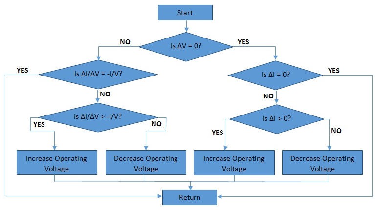
And more precisely you will need to measure PV voltage, PV current and variations of these parameters.
Then you must have a way to pilot the voltage of your panel… That is a DC/DC converter controlled by a micro controller !
The MPPT controller hardware
As stated before we need a good DC/DC converter.
My first source of inspiration was this excellent design proposed by TechBuider on Youtube : DIY 1kW Arduino MPPT Solar Charge Controller (WiFi ESP32) - YouTube
This guy made a wonderful job of explaination and even proposed a fully working Open source and Open Hardware system : 1kW Arduino MPPT Solar Charge Controller (ESP32 + WiFi) : 46 Steps (with Pictures) - Instructables
From this project I mainly decided to find a Synchronous Buck Converter able to get the best efficiency for DC/DC conversion compared to cheap asynchronous ones.
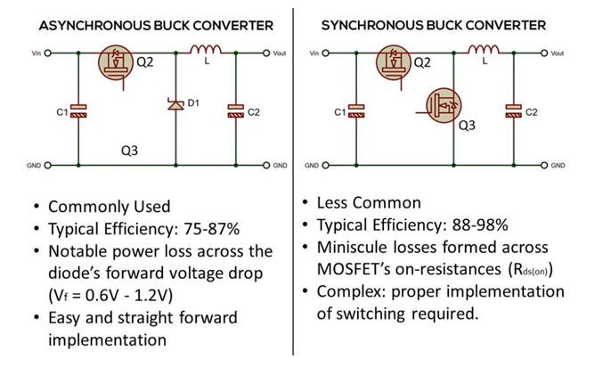
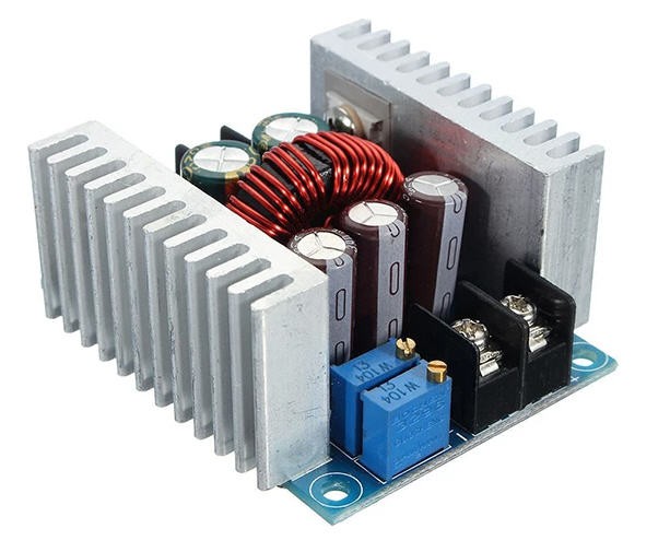
So I tried to find a ready made DC/DC Synchronous Buck converter. And I found this one which is also very cheap (<7$)
Interestingly, it is based on a LM25116 chip which is, as stated into the datasheet, : “a synchronous buck controller intended for step-down regulator applications from a high voltage or widely varying input supply ».
Looking further, I found a schematics of this device (retro engineered) and I could propose a “hack” of this system to transform it into a MPPT controller.
You can refer to the MPPT electronics log for further details.
Basically the “hack” consists in :
- Adding a voltage measurement point both for PV voltage and Output Voltage
- Adding a current measurement
- Adding a control of output voltage from the ESP32 microcontroller
This being done the hardware of the MPPT controller was finished and ready to be hidden into a "nice" 3D printed enclosure.
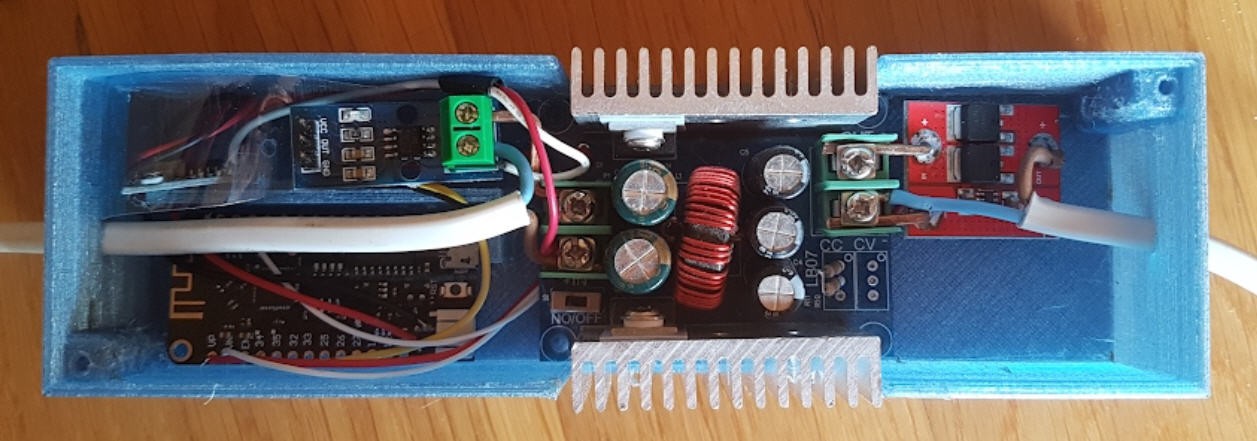
As you can see, the heatsinks of the Buck converter are directly exposed to the ambiant air. No fan is needed as the overall current of my solar panel is far below the max current of this converter. However do not touch these heatsinks they are "more than warm" !
BTW this is another reason why you should use high temperature filament for the enclosure... and PET bottle filament is perfect for this !
MPPT controller software
Looking at the controller picture you may be surprized that there are no button, no rotary encoder and even no screen... In the "keep it cheap and simple spirit" and as we are living in a modern world where everybody has a smartphone, I decided to use it to monitor and control the MPPT controller.
So it should just boot when put face to the sun and start to do its job !
And whenever it sees a "friendly phone" start to communicate with it.
Hopefully the ESP32 MCU is equiped with both Wifi and Bluetooth Low Energy. I do use both, but mainly BLE for monitoring and control.
I have thus writen an Android App to handle all the GUI to control the Controller and to monitor in real time its status.

It is still a very crude App but works as intended. It allows :
- to display real time values of any parameter (Vin, Vout, Iin, Iout, Power...)
- to select the operation mode (solar charger, power supply, ...)
- to select the battery type (lead acid, lipo 1s, 2s, 3s or 4s)
Please refer to the MPPT software logs for more details and to get the source codes both for Android and ESP32.
The whole system running
If you are here, still reading this long description, then you probably would like to see the system in operation !
Testing conditions :
- location Toulouse France 43° North latitude
- time 13h30 UTC (that is 1h30 after noon. Local time 15h30 ... Video speech a little confusing... sorry)
- MPPT controller ON in Solar Charger mode for Lead Acid battery (during the video)
At the beginning of the video the Solar Tracker was without panel voltage. Only the lipo bat was powering the ESP32. The motion was thus blocked (low voltage on the motors) during almost 20 minutes.
Then I re powered the Solar Tracker and pushed the reset button to force motion computation and motion itself.
All this is visible on the video here.
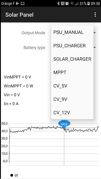
In addition here is a screen copy of the MPPT Android App where you can see three phasis :
1) starting in MPPT mode at a voltage around 11V during a shadow period due to cloud
2) MPPT mode recovering sunny condition (max power of the panel applied on the output)
3) switching to Solar Charger Mode with the lead Acid connected and almost full. see drop of Voltage on the curve.
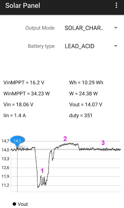
You can also see that the VinMPPT detected by the firmware is at 16.2V which is rather close to the specification.
The current and power which are fed into the battery are not very high (battery almost charged at 14.07V at input of the ideal diode), the cut off (float mode) should be reached quite soon.
Time lapse of the tracker
Here is a timelapse of my solar tracker during sunset. Speed is increased by 480.
Thus 9s last in reality 1 hour and 14 minutes.
It was 17h30 pm when starting recording. Shadow of my home covered quite soon the panel but the tracker kept running on the battery, and this was the expected behavior: no dependence on any external sensors!
and a few minutes later the panel should perfom its "go to East flip"!
And the final timelapse during 4 hours of acquisition and with the new Azimut axis fully working
A few words of conclusion
Solar panels were, for me, a real mystery when I started this project.
I did learn a lot since october last year. This project is still a work in progress, but the current status is that I have a working prototype for both the solar Tracker and the MPPT Controller.
They are exactly as expected : very light, portable, fully automatic and thus easy to use even in the fields.
These devices are really useful if you want to extract the maximum power from your panel. Many will say that for low power panels the extra cost does not worth the gain... Well, ... unless you build a really cheap system !!!
Is it cheap enough ?
Here is the Bill Of Material for all the components :
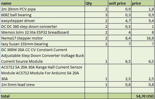
So it is really under 55$, but to be honest I didn't take into account the "ideal diode" that I added to the original design as the schottky one was getting too hot!
But at this price it even icludes a 4s3p battery pack!
So I would say that YES it is cheap enough even though prices are getting higher and higher nowadays... That's a pity but it is outscope of the challenge!
Licenses
Unless otherwise stated, all works presented here that are not based on software/code are subject to the Creative Common Attribution license .
The complete legal text can be found here
Unless otherwise stated, all software/code-based works presented here are subject to the GNU General Public License v3.0
The complete legal text can be found here