 JP Gleyzes
Azimuth axis
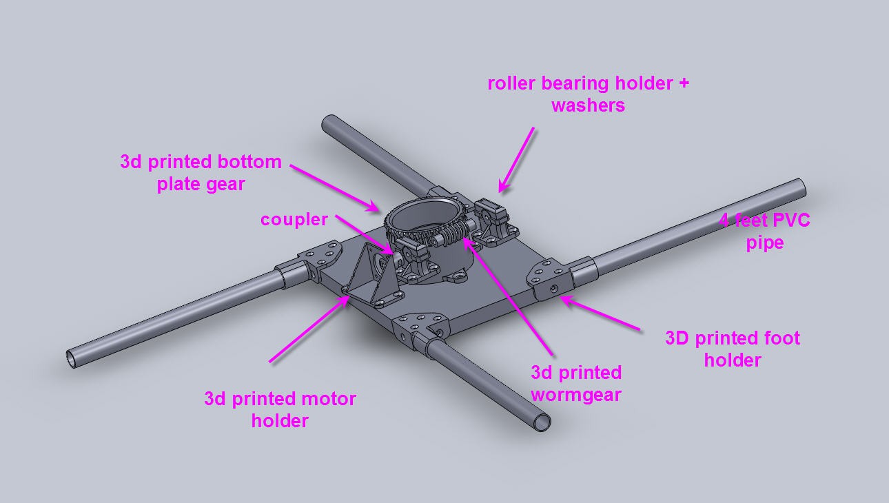
On this CAD picture only the bottom plate is shown.
Between top and bottom plate is inserted a lazy Susan turntable bearing.
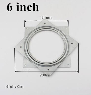
Be sure to choose a 6 inch model . The main gear must be able to enter the hole of the lazy Susan.
It must also be perfectly centrered with the Lazy Susan center. Be careful.
Here is a view of this axis finished :
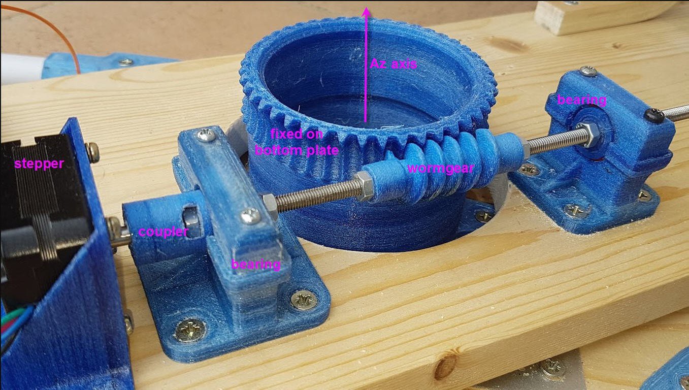
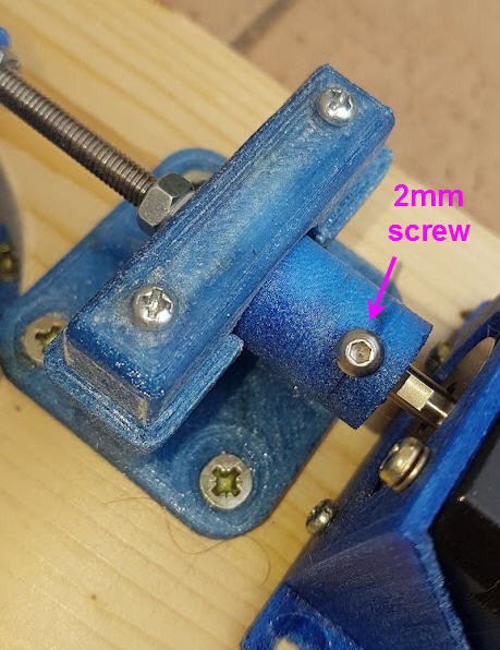
The coupler must be fited with a 5 mm screw (visible on the top picture) and a 2mm one on the other side
Align everything and screw the bearings holders in place. Lock any motion of the wormgear with 5mm nuts.
Do the same for the elevation axis :
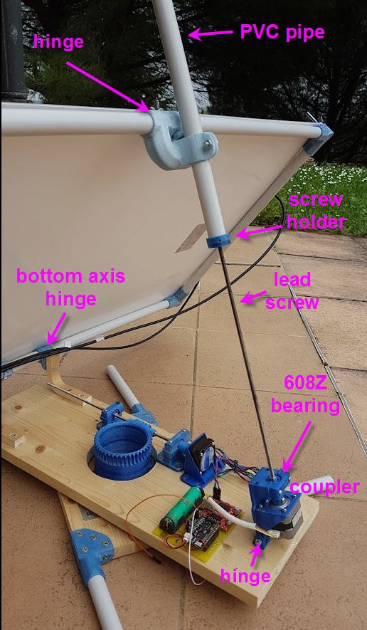
All the 3D printed "hinges" must rotate freely on their respective axis. FIle the parts to achieve this !
Here is a detailled view of the "screw holder"
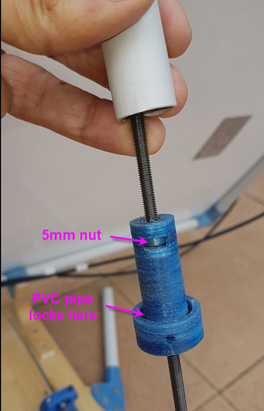
This is the part which achieves the translation of the linear actuator of the Elevation axis. As it is fixed to the PVC pipe which is also fixed to the top hinge of the frame, when the lead screw rotates then this part can only go up or down, pushing or pulling the top of the frame !
As visible on the picture (black dirty color), you should add a few drops of oil on the leadscrew to ease rotation.
Discussions
Become a Hackaday.io Member
Create an account to leave a comment. Already have an account? Log In.