 ElectronicABC
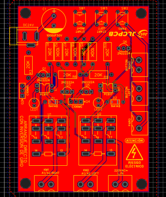
GERBER PCB
https://mega.nz/file/7YxWCKwA#nEuxJds3FPH3isQ78ZK4wHAZhPC1u3k2HArkeHzOBw0
DATASHEET SCR C106DG
https://mega.nz/file/TN5RRK5J#LuROspQhA5OpTO6GbCLjuvHn70rFaZUFlkAKdgf7k1Y

What is the use of reversing the rotation in a motor?
The reversal of rotation allows the motor to exert mechanical force in opposite directions, although not simultaneously. For example, it can be used to raise a vehicle platform, and reverse the turn to stop it.
How does it work?
The operation is very easy since with a RIGTH pulse we will initiate the first start to the right, when it is in operation no matter how much you press the second LEFT start it will never enter since the first start is in operation. Then to change turn I have to turn off the start according to which we press STOP and this deactivates me and allows me to enter the next LEFT or left start and vice versa.
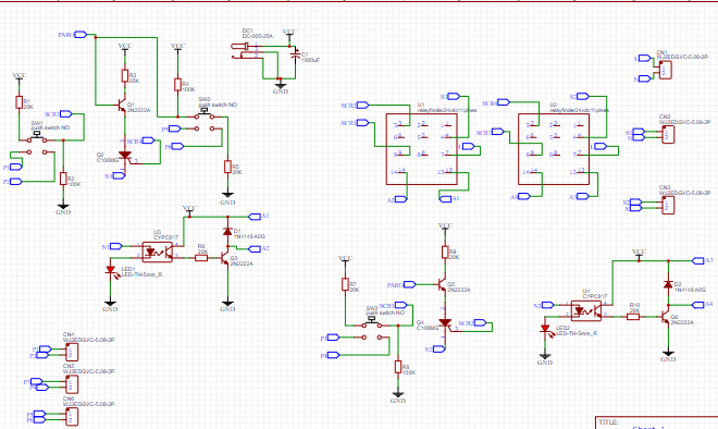
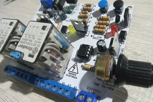
The electronic circuit is very easy and understandable since the main brain is the SCR for interlocking the RELAY and the motor to be used. It should be noted that this circuit is only useful for the control system while the force system will be done through contactors that will handle the power of the three-phase motor according to the needs that we will require. A main advantage of this circuit is that we will no longer use auxiliaries for the contactors.
SCR
The silicon controlled rectifier (SCR) is a type of thyristor made up of four layers of semiconductor material with a PNPN or NPNP structure. The name comes from the union of Tiratrón (tyratron) and Transistor.
Thyristor:
An SCR has three connections: anode, cathode, and gate. The gate is responsible for controlling the flow of current between the anode and the cathode. It basically works like a controlled rectifier diode, allowing current to flow in only one direction. As long as no voltage is applied to the gate of the SCR, conduction does not start and the instant that voltage is applied, the thyristor starts to conduct. Working in alternating current, the SCR is de-excited in each alternation or half cycle. Working in direct current, a forced blocking circuit is needed, or else interrupt the circuit.
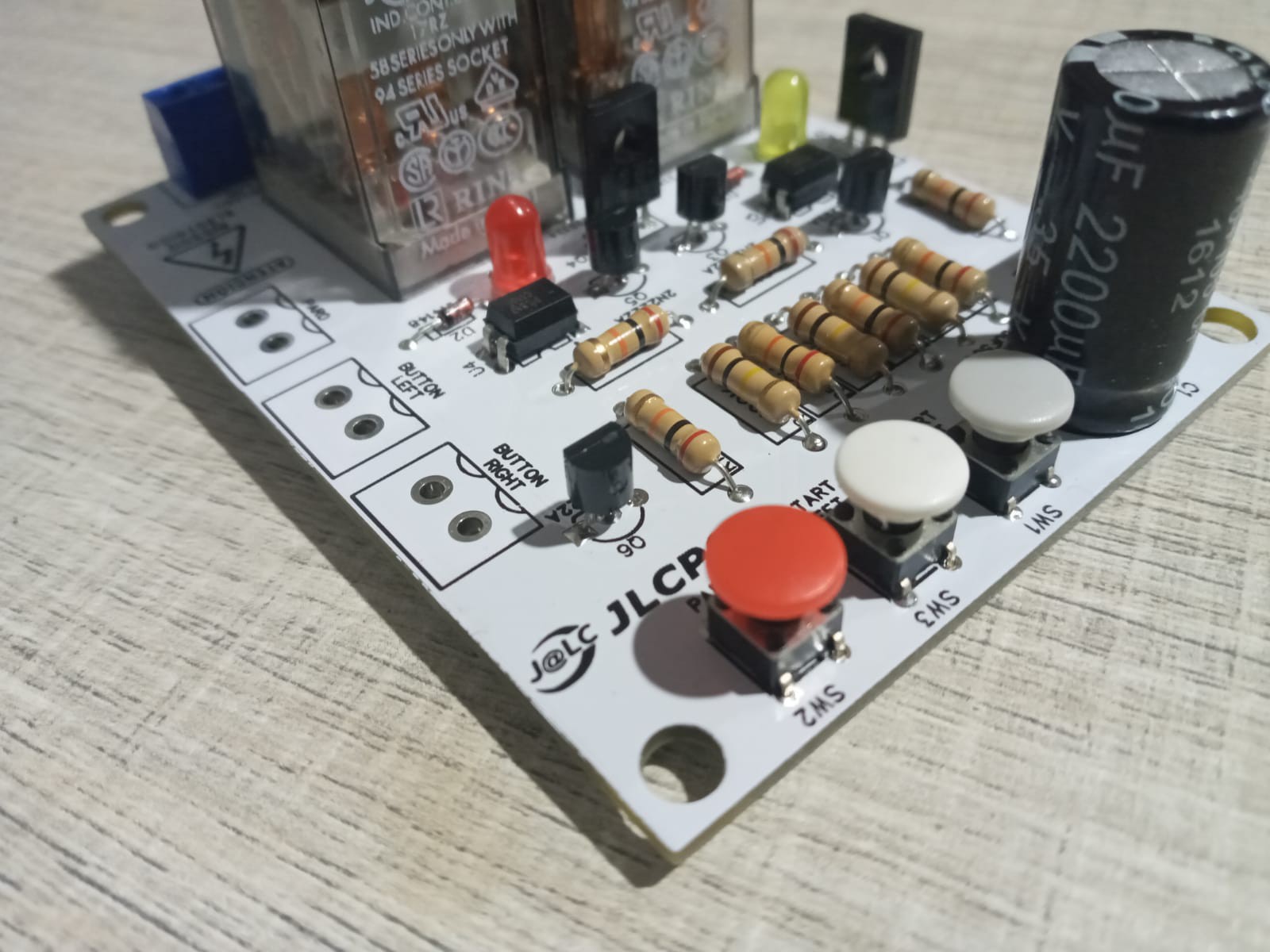
ELECTRONIC COMPONENTS:
· 1 DC JACK
· 1 ELECTROLYTIC CAPACITOR 1000UF35V
· 3 BUTTONS NO
· 4 TRANSISTORS 2N2222A
· 2 SCR C106DG
· 2 PC817 OPTOTRANSISTORS
· 7 RESISTORS 20K 1/2W
· 3 RESISTORS 100K 1/2W
· 2 DIODE 1N4148
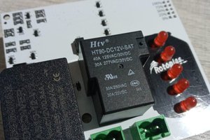
· 2 RELAYS 24VDC 3WAYS
· 3 TERMINAL BLOCK BLUE 2 PINS
FEATURES AND BENEFITS:
· VIN 24VDC
· Imax 0.050 A or 50 mA
· effective system
· Low consumption in control system
· Interlock integrated in the control system
· Easy maintenance
· Force stage contactor activation
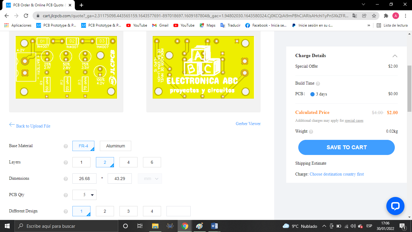
JLCPCB
We thank JLCPCB for professional PCBs
Order your PCBs here
5PCBS AT $2
GERBER PCB:
https://mega.nz/file/7YxWCKwA#nEuxJds3FPH3isQ78ZK4wHAZhPC1u3k2HArkeHzOBw0

 ElectroBoy
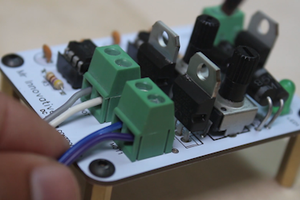
 Mrinnovative