 Open Green Energy
Specification:
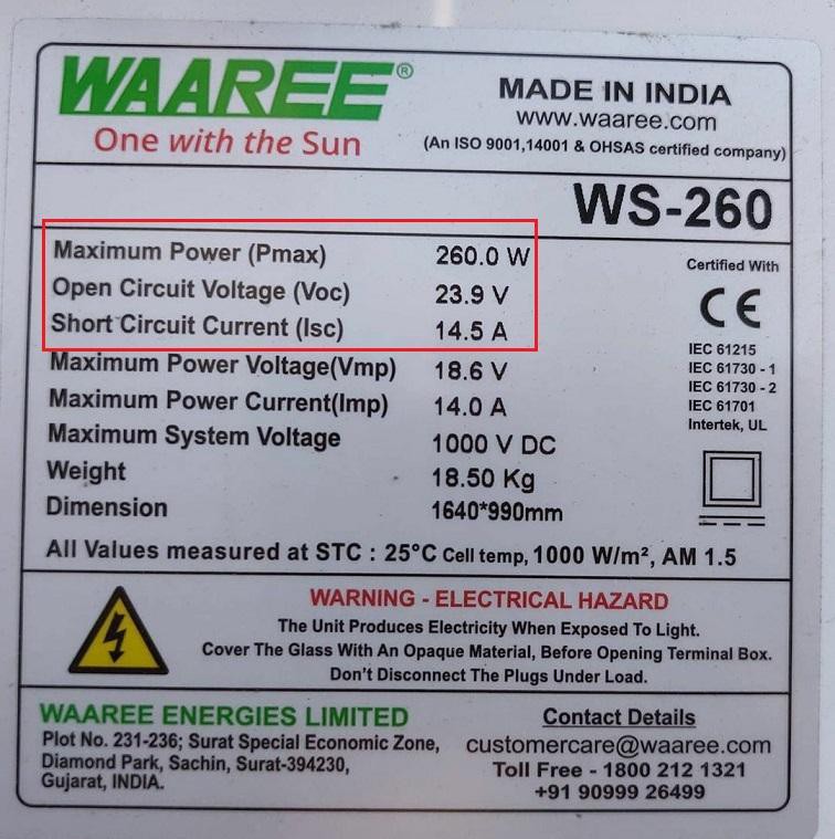
1. Input Voltage - 0- 24V ( Can be extended up to 50V )
2. Input Current: 0 -15A
3. Solar Panel Rating - 250W (12V ) / 500W ( 24V )
How It Works?
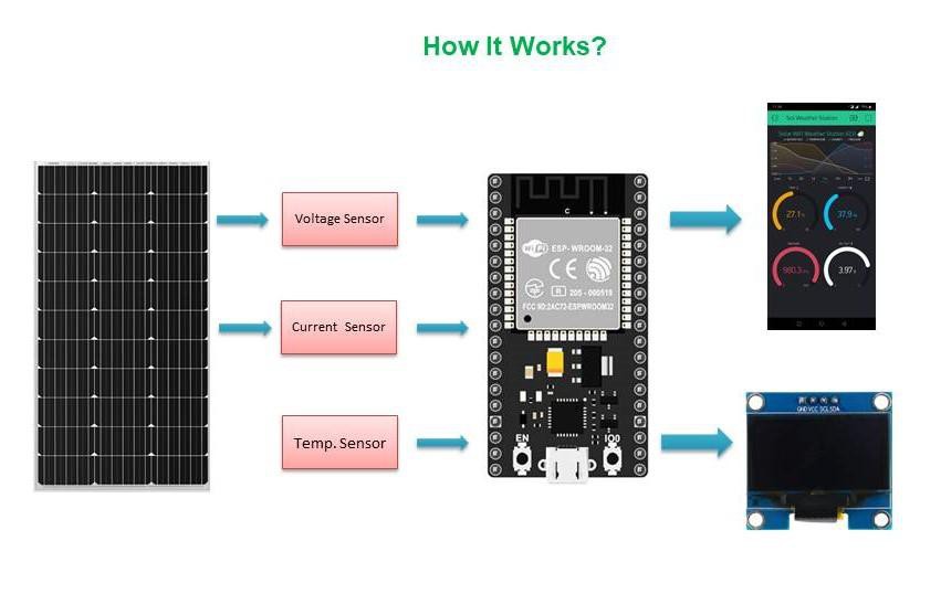
The Solar panel voltage and current are sensed by the voltage and current sensor respectively. Here, a voltage divider network is used to measure the solar panel voltage, and the AC723 hall effect current sensor is used to measure the solar panel current. Similarly, the ambient temperature is sensed by the DS18B20 temperature sensor.
The raw sensor data from all the sensors are processed by an ESP32 board and do all the necessary maths to calculate the power and energy. The processed data is then sent to an OLED display for local monitoring and also to the cloud for remote monitoring. The remote monitoring is done through the Blynk app installed on a Smartphone.
Measuring Voltage:
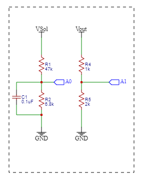
The solar panel voltage is sensed by a voltage divider network consisting of two resistors R1=47k and R2=6.8k. The output from the R1and R2 is connected to ESP32 analog pin GPIO pin 34. The output from the voltage divider is smoothed out by using a ceramic capacitor C1.
Voltage Measurement :
ESP32’s analog inputs can be used to measure DC voltage between 0 and 3.3V. The solar panel that I have considered can generate 24V ( Open Circuit Voltage). To read this voltage we have to step down the voltage which can be done by using a voltage divider network.
For a voltage divider circuit
Vout = R2/(R1+R2) x Vin
Vin = (R1+R2)/R2 x Vout
The analogRead() function reads the voltage and converts it to a number between 0 and 4095
Calibration :
We’re going to read the output value with one of the analog inputs of Arduino and its analogRead() function. That function outputs a value between 0 and 4095 which is 3.3/4095 for each increment
Vin = Vout*(R1+R2)/R2 ; R1=47k and R2=6.8k
Vin= ADC count * ( 3.3/4095 ) * ( ( 47+6.8) / 6.8 ) Volt
You can use a solar panel with higher voltage by selecting the appropriate resistors R1 and R2.
To select the voltage divider resistance values, you can use this online calculator.
Measuring Current :
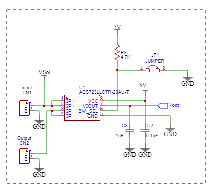
For the current measurement, I used a Hall Effect current sensor ACS 723 -20AUvariant. There are other variants of ACS723 Sensor based on the range of its current sensing. The ACS712 sensor reads the current value and converts it into a relevant voltage value, The value that links the two measurements is Sensitivity. The output sensitivity can be obtained from the datasheet. As per the datasheet, the sensitivity is 200mV / A
Calibration:
analog read value = analogRead(Pin);
ADCVoltage = (3.3/4095)*analog read value
Current in amp = ( ADCVoltage – Offset Voltage ) / sensitivity
As per data sheets offset voltage is 0.1 * Vcc ( 0.5V ) and sensitivity is 200mV/A
Note: The output from the ACS723 is stepped down by a voltage divider network consisting of R4 and R5.
Measuring Temperature :
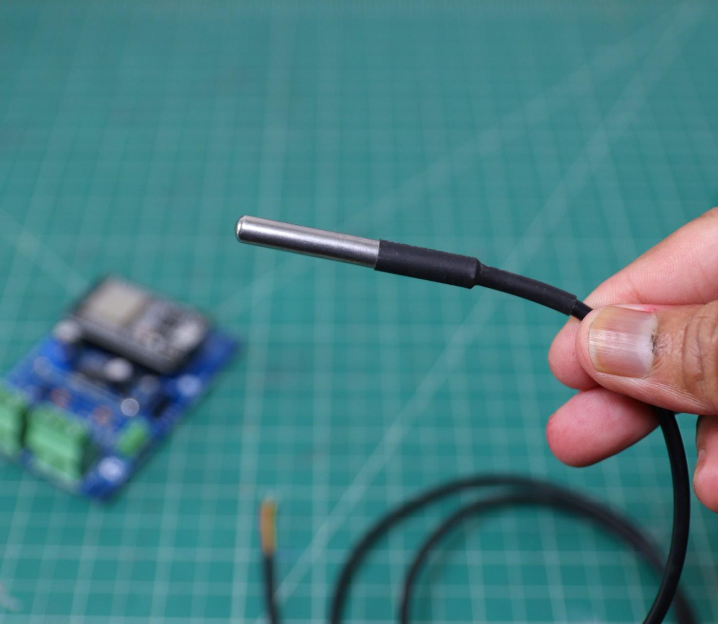
I have used an external DS18B20 probe for measuring the ambient temperature. It uses a one-wire protocol to communicate with the microcontroller. One-wire devices need a pull-up resistor connected to their signal line to be properly read by your board. Here, I have used a 4.7K resistor ( R6 ) as a pull-up resistor.
It can be hooked up to the PCB through the 3pin screw terminal.
To interface with the DS18B20 temperature sensor, you need to install the One Wire library and the Dallas Temperature library. You can read this article for more details on the DS18B20 sensor.
The connection is as follows:
Red Wire -> Vcc
Yellow Wire -> DATA
Black Wire -> GND
All the above are clearly labeled on the PCB for avoiding any confusion.
Interfacing OLED Display :
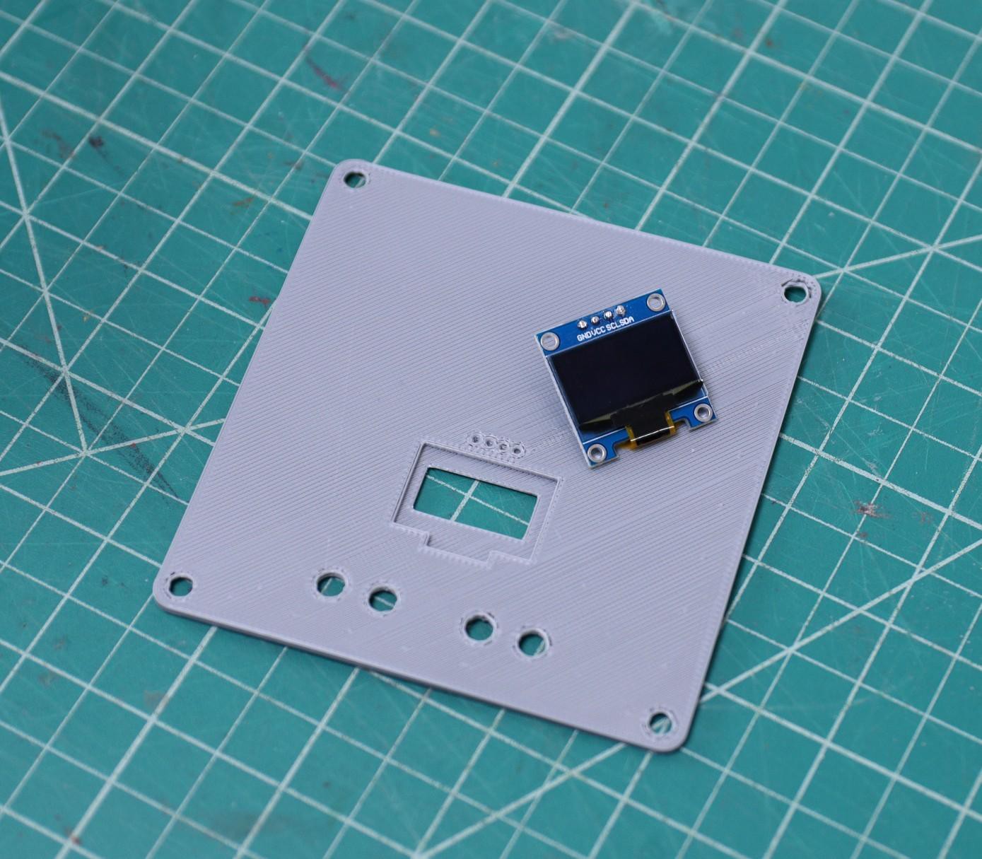
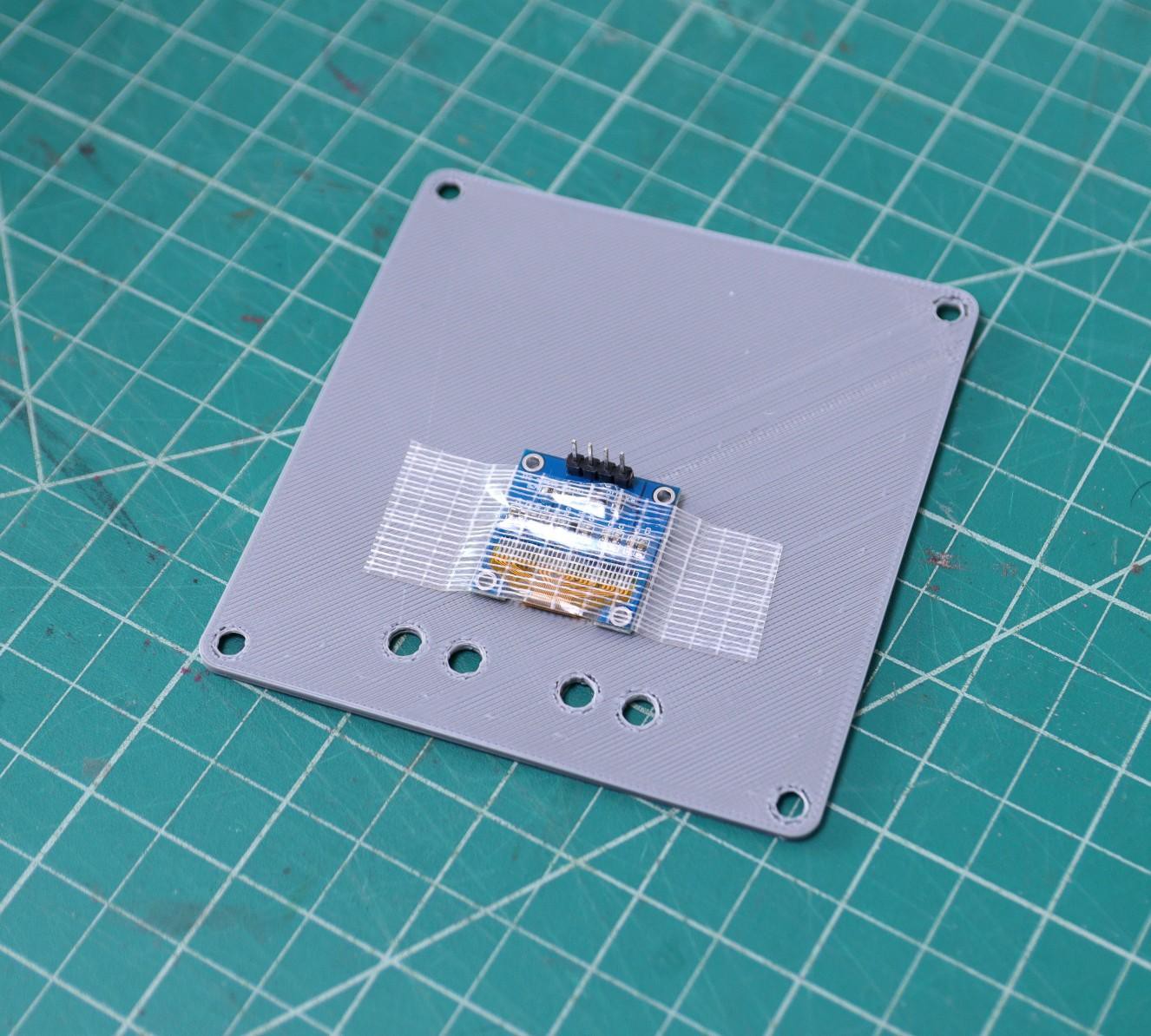
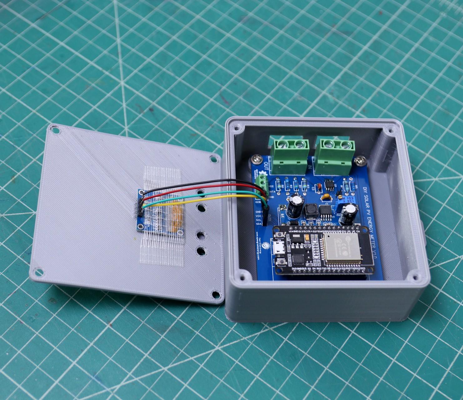
To display the solar panel parameters locally, I have used a 0.96" OLED display. It has a 128 x 64 resolution and uses an I2C bus to communicate with the ESP32. Two pins SCL (GPIO22), SDA (GPIO21) in ESP32 are used for communication.
I am using the Adafruit_SSD1306 libraryto display the parameters. First, you have to download the Adafruit_SSD1306. Then installed it.
The connections should be as follows:
ESP32 - ->OLED
3.3V --->VCC
GND -->GND
GPIO21----> SDA
GPIO22----> SCL