 Ruediger F. Loeckenhoff
***SCOPE***
We want to provide a very cost efficient control unit which is capable of tracking solar panels to the sun with a high precision even with imprecise solar tracker mechanics. In particular it tracks concentrator photovoltaic (CPV) modules that require a tracking precision of 0.1 degrees. With this work we hope to contribute to the clean energy transition.
***PROJECT STAGES***
A first version of this control is based on an arrangement of breakout boards. Follow the links to Github www.github.com/solhunter to find detailed building instructions and the source code (MIT license).
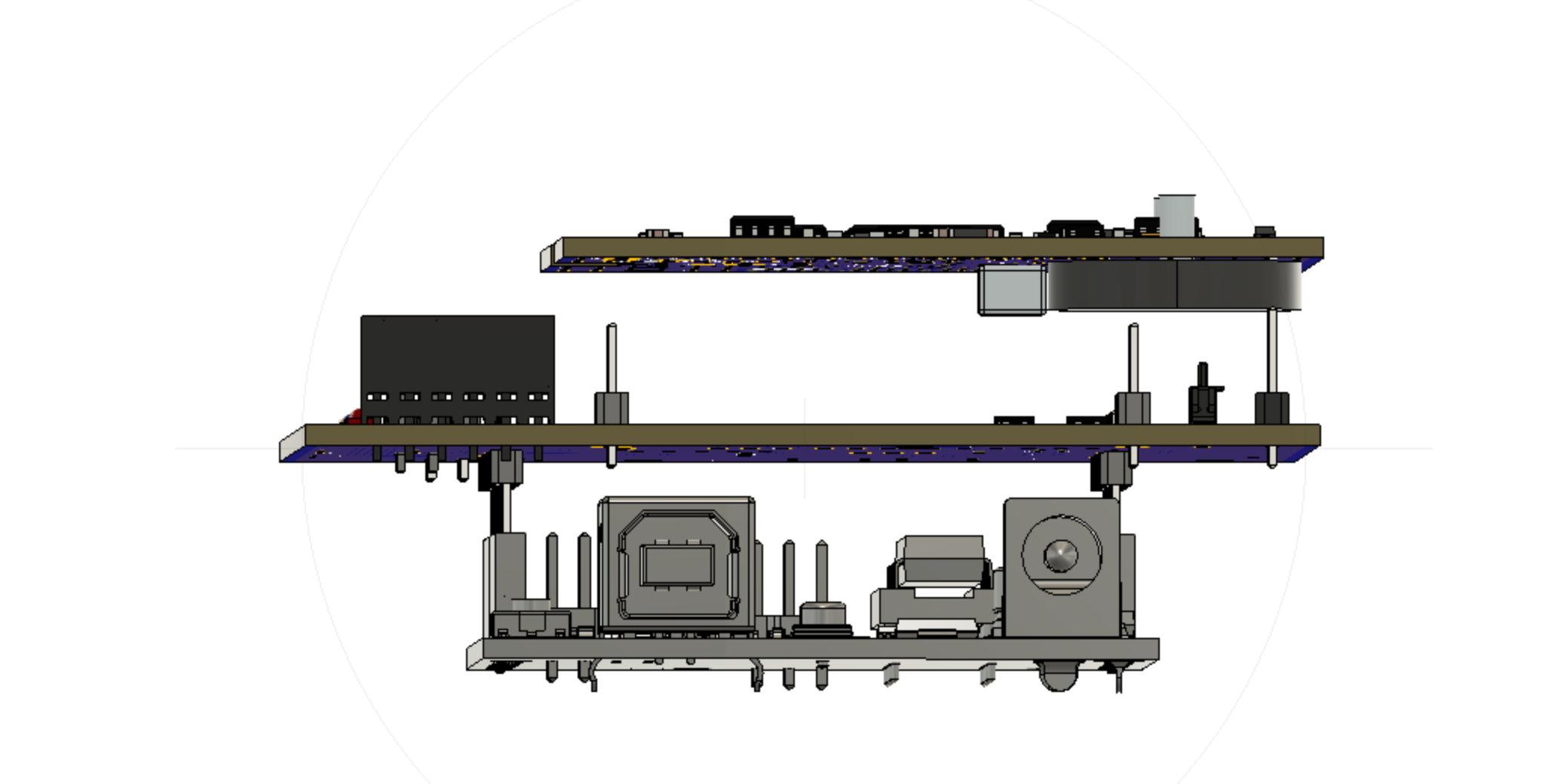
In the second project stage we have integrated the components of the first stage on a single board. We have received and successfully tested 25 pcs of a refined version V2.0f of this board. You can find the complete design files and CAM outputs in this reposit at hackaday (MIT license).
As a side activity we are promoting the board for general robotics – either as an integrated Arduino compatible ATMEGA328 controller board or as an I2C device that can extend the capabilities of e.g. a Raspberry Pi.
***THE STORY***
Typically, tracker controllers are control cabinets with cables running to limit switches and encoders which are notoriously unreliable as the cables degrade in the UV light or the sensors get flooded with rain. A failed sensor or encoder may make the tracker run beyond its limits and self-destruct. Furthermore, the control cabinet gets into the way of the moving generator. I have even seen trackers running on a central PC connected to two Siemens SPS or at least running on a one board PC. What a waste of money, resources and electric energy.
Now imagine what a “mature” solar tracker controller would look like. Think of the solar tracker as a dishwasher. There would be a small circuit board somewhere in the housing with not much more on it than a µC, some FETs and possibly some extra sensors. But this control didn’t exist. Someone had to make it, so I started this job. I had no idea about microcontrollers but I knew about solar trackers. Now I know about microcontrollers too, and it is great fun. Thank you, Arduino community. As I moved along, I learned about the MPU9250 9-axis compass and figured out that it would be perfect for the astronomic tracking without any external sensors. The real challenge was the self-calibration routine but I successfully solved this riddle. It even works on trackers with an extensive amount of magnetic steel as I confirmed when I was allowed to test one of the prototypes on a 10 m2 CPV tracker for a day. You can find Arduino code and the detailed building and operating instructions at www.github.com/solhunter.
Even so this assembly of breakout boards works very well, it probably wouldn’t be considered a professional solution and I don’t have any experience in circuit board design. So, I greatly thank Ermanno Antonelli for joining forces with me. He is a professional in electronic board design and invested many hours in this project to come up with the present board design.
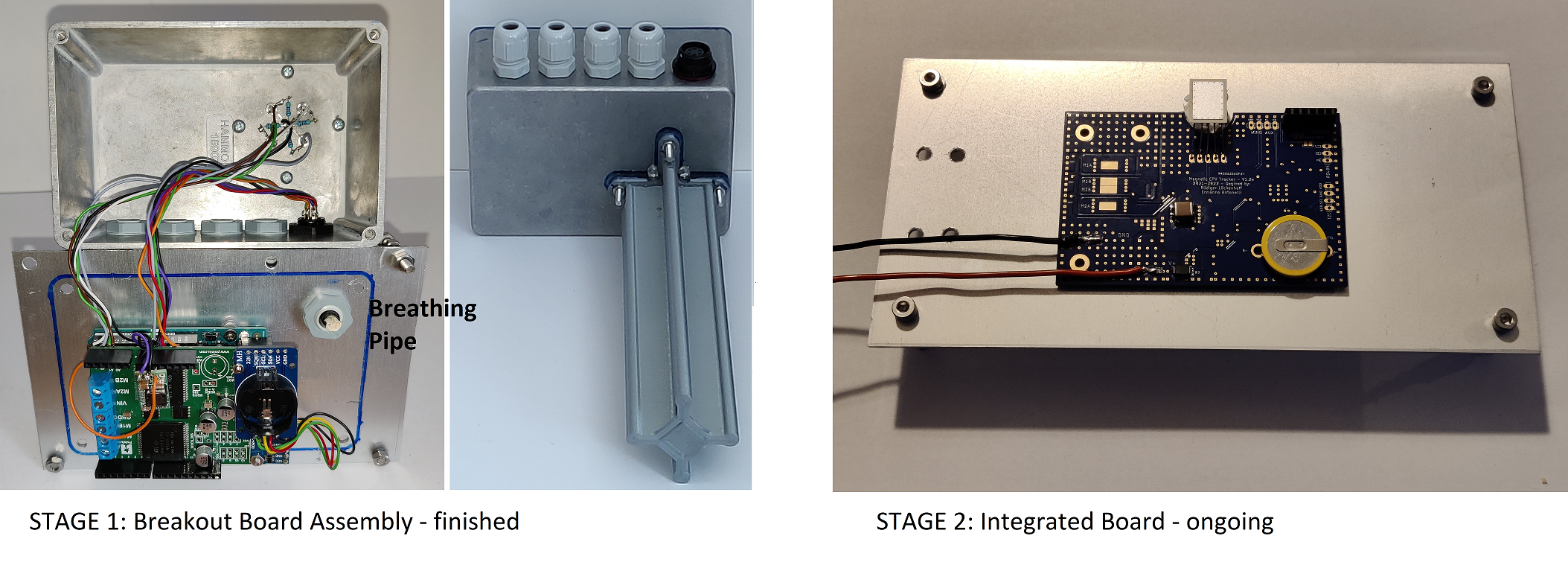
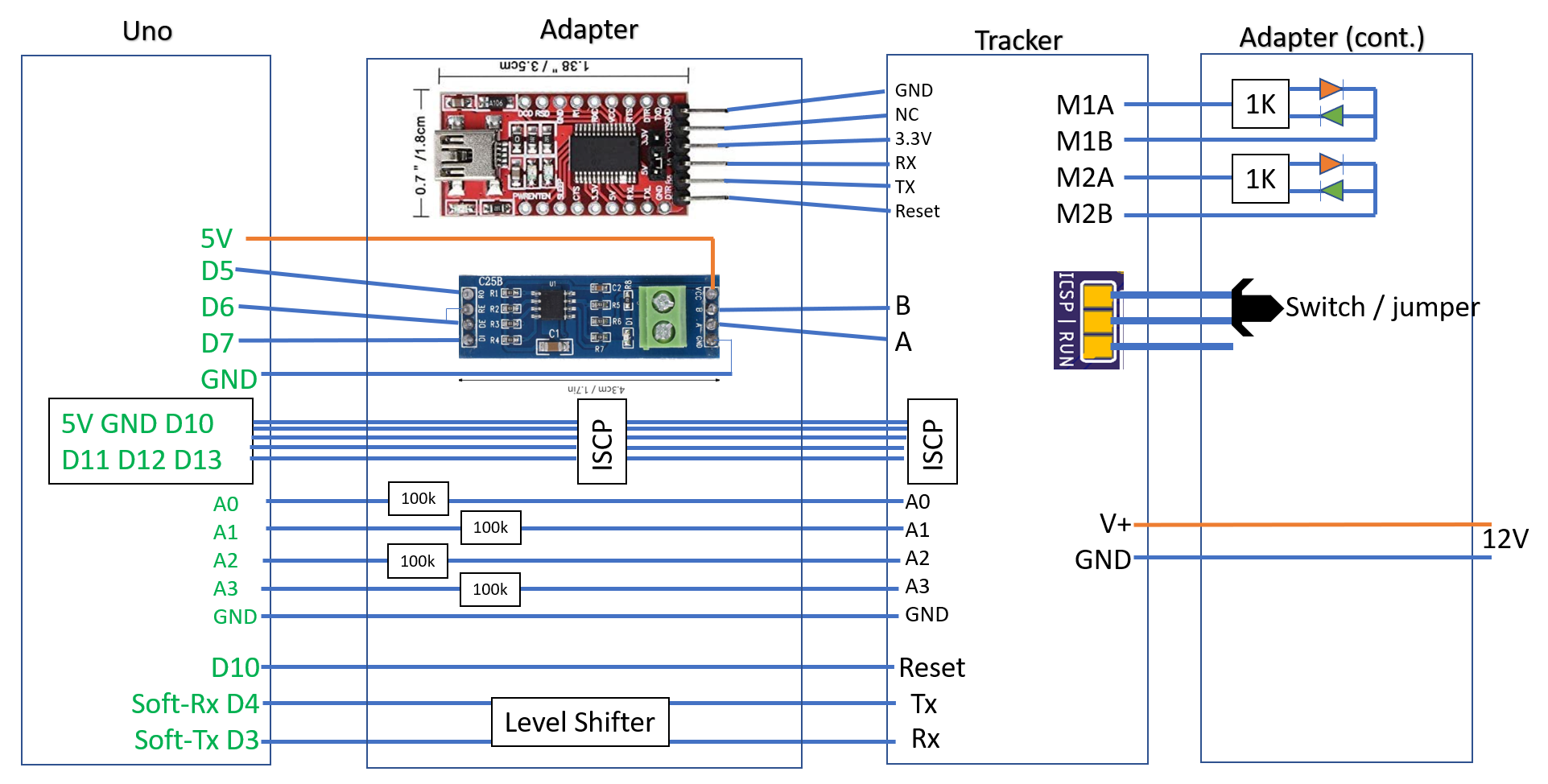
***STAGE 1: THE BREAKOUT BOARD ASSEMBLY***
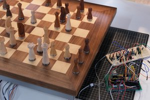
A dual VNH5019 shield provides 6-24V, 0-12A motor control to an Arduino UNO. A real time clock and an MPU9250 compass chip are connected with only a few air wires. Everything together is stored in a sealed aluminum box with a tracking sensor on one side. Please see the linked video and the file 2021_08_14_Full_description.pdf for details.
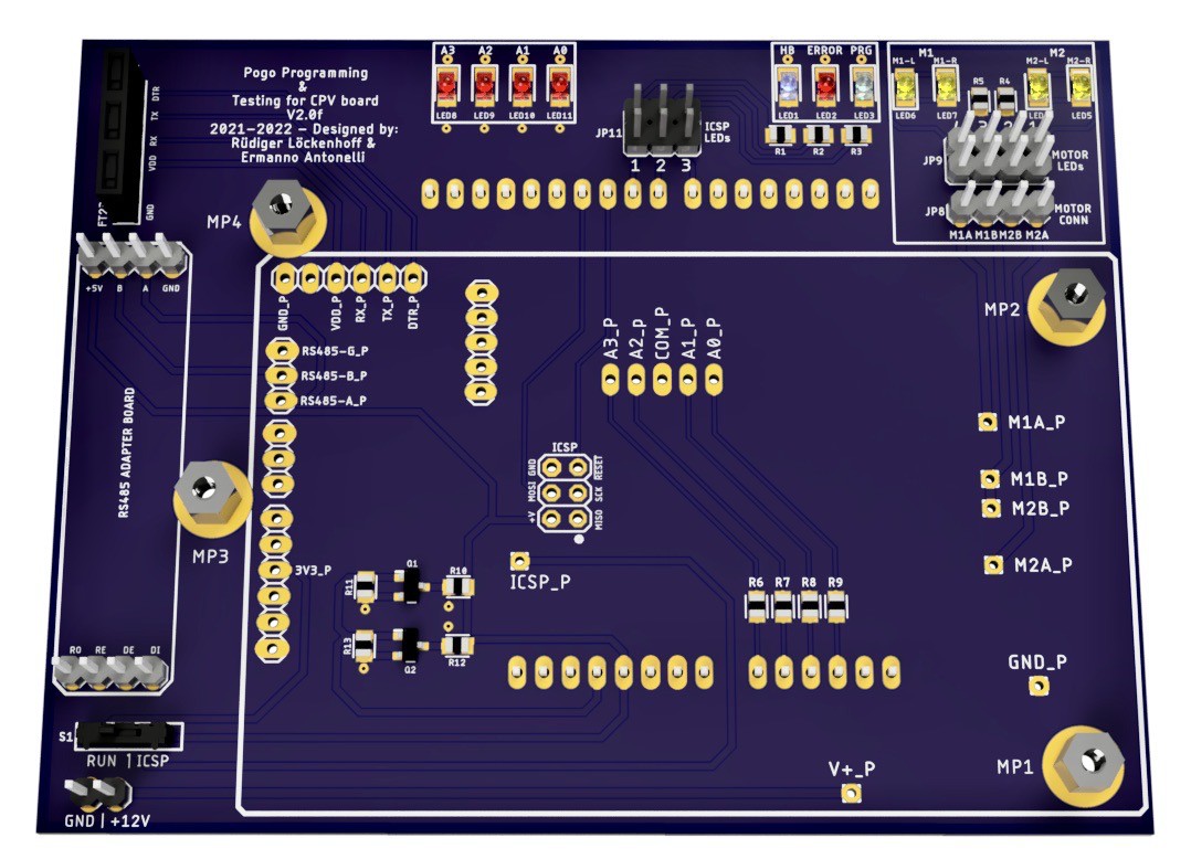
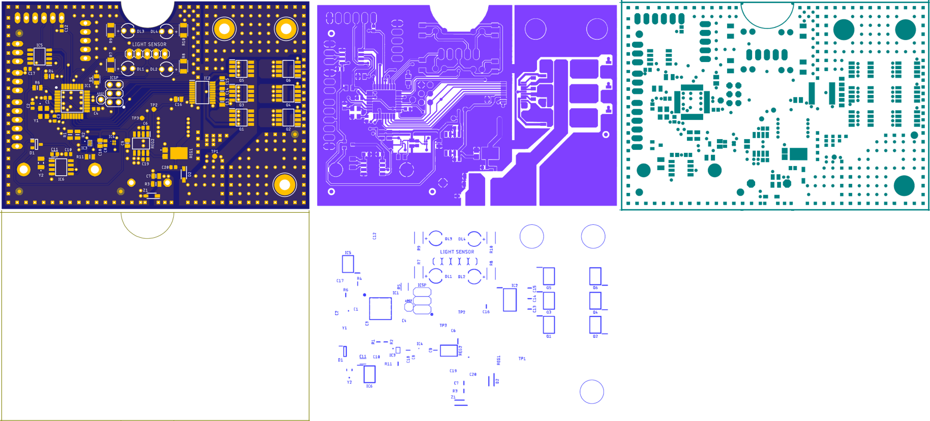
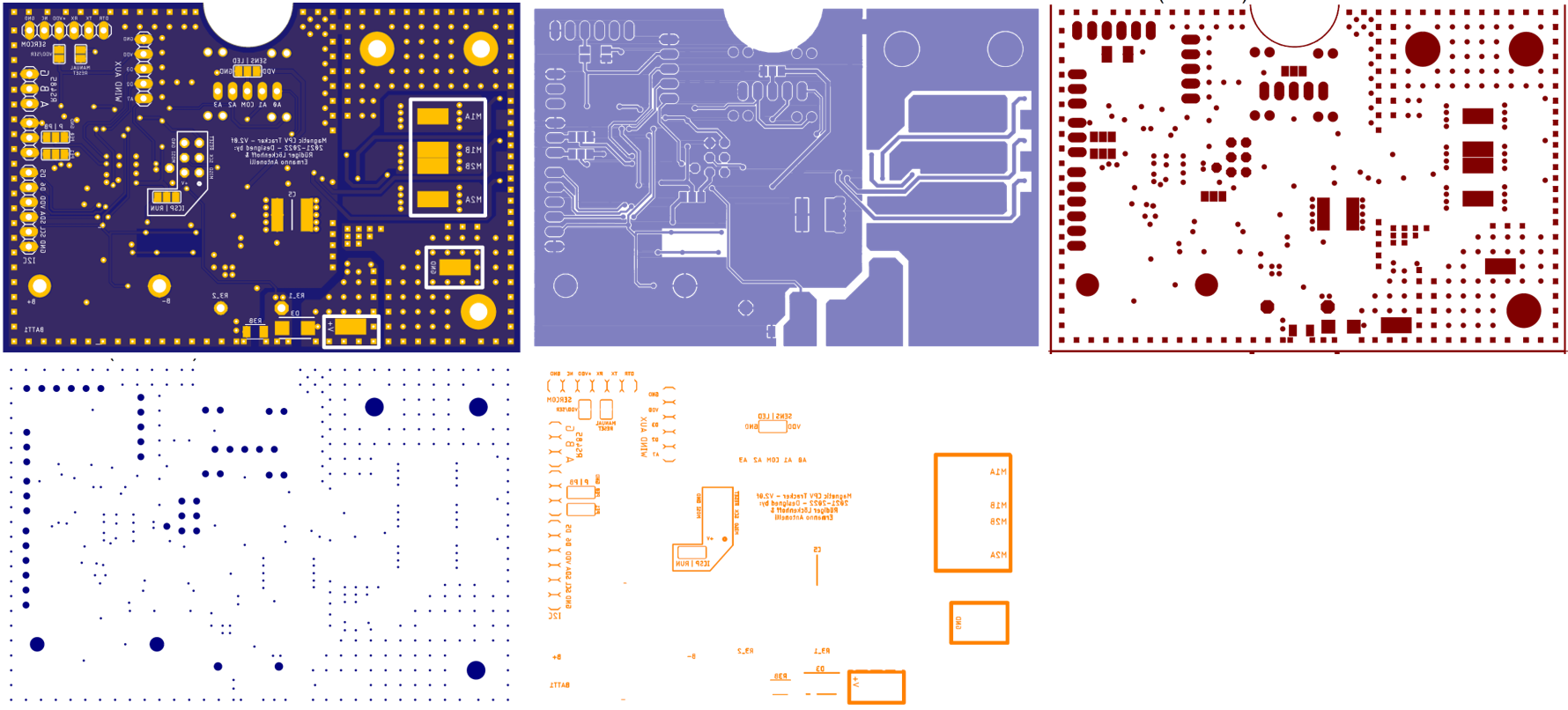
***STAGE 2: THE MAGNETIC CPV TRACKER V2.0f BOARD***
The all in one control board follows the same principles as the breakout board assembly. Yet we had to replace the discontinued MPU9250 9-axis-compass and we chose chip level magnetic and acceleration sensors by MEMSIC instead. Furthermore, we replaced the costly VNH5019 motor drivers with an arrangement of 6 FETs and a DRV8300 gate driver.
In the present board design, we also included RS485 communication which will be...
Read more »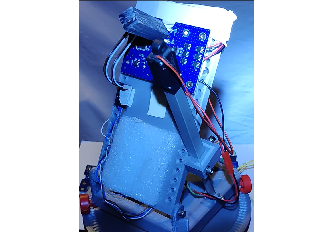


 Phantom Chessboard
 anfroholic
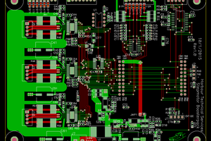
 Bharbour
 nerd.king
Hi Everyone, Ermanno here.
I'm thrilled to be part of this project with Rüdiger being the scenes. I have contributed to the electronics design and PCB miniaturisation. All things consider, we managed to packed a lot of features in such a small board. Working with Rudi we pushed the concept of doing more with less even further and I think we succeeded. Now working on the test gig for mass production. If you look at the open source files, most of components are either Eagle standard libraries os sourced via SamacSys plugin. refer to the note in the schematics for any component question and feel free to give us a shout.
All the Best,
Ermanno