Close
0%
0%

Open Concentrating PV Solar Tracker Controller

Achieve better than 0.1° sun tracking accuracy with a compass a tilt sensor and a shading beam sun sensor.

Public Chat
Similar projects worth following
Concentrating Photovaltic CPV systems have up to 35% efficiency but require highly precise dual axis tracking. Normal flat plate PV panels are also profiting from solar tracking that increases the yield especially in the morning and the evening by keeping the panels aligned to the sun. Commonly these solar trackers are controlled by control cabinets that are connected to end switches and encoders to follow the calculated sun path. We are replacing this complicated and expensive arrangement by a single cost effective board that controls the motors, follows the calculated sun path with a magnetic compass and aligns itself with a precision of much better than 0.1° when light is falling on the integrated sun sensor. The project is published under MIT license and includes board files, Arduino code and documentation. Prototypes are available upon request.

***SCOPE***

We want to provide a very cost efficient control unit which is capable of tracking solar panels to the sun with a high precision even with imprecise solar tracker mechanics. In particular it tracks concentrator photovoltaic (CPV) modules that require a tracking precision of 0.1 degrees. With this work we hope to contribute to the clean energy transition.

***PROJECT STAGES***

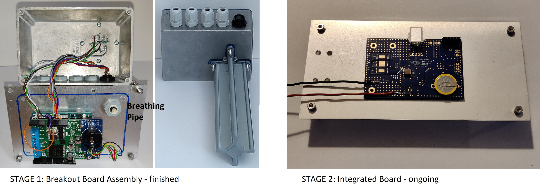
A first version of this control is based on an arrangement of breakout boards. Follow the links to Github www.github.com/solhunter to find detailed building instructions and the source code (MIT license). 

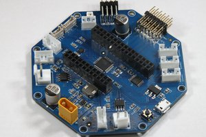
In the second project stage we have integrated the components of the first stage on a single board. We have received and successfully tested 25 pcs of a refined version V2.0f of this board. You can find the complete design files and CAM outputs in this reposit at hackaday (MIT license).
As a side activity we are promoting the board for general robotics – either as an integrated Arduino compatible ATMEGA328 controller board or as an I2C device that can extend the capabilities of e.g. a Raspberry Pi.

***THE STORY***

Typically, tracker controllers are control cabinets with cables running to limit switches and encoders which are notoriously unreliable as the cables degrade in the UV light or the sensors get flooded with rain. A failed sensor or encoder may make the tracker run beyond its limits and self-destruct. Furthermore, the control cabinet gets into the way of the moving generator. I have even seen trackers running on a central PC connected to two Siemens SPS or at least running on a one board PC. What a waste of money, resources and electric energy.

Now imagine what a “mature” solar tracker controller would look like. Think of the solar tracker as a dishwasher. There would be a small circuit board somewhere in the housing with not much more on it than a µC, some FETs and possibly some extra sensors. But this control didn’t exist. Someone had to make it, so I started this job. I had no idea about microcontrollers but I knew about solar trackers. Now I know about microcontrollers too, and it is great fun. Thank you, Arduino community. As I moved along, I learned about the MPU9250 9-axis compass and figured out that it would be perfect for the astronomic tracking without any external sensors. The real challenge was the self-calibration routine but I successfully solved this riddle. It even works on trackers with an extensive amount of magnetic steel as I confirmed when I was allowed to test one of the prototypes on a 10 m2 CPV tracker for a day. You can find Arduino code and the detailed building and operating instructions at www.github.com/solhunter.

Even so this assembly of breakout boards works very well, it probably wouldn’t be considered a professional solution and I don’t have any experience in circuit board design. So, I greatly thank Ermanno Antonelli for joining forces with me. He is a professional in electronic board design and invested many hours in this project to come up with the present board design.

***STAGE 1: THE BREAKOUT BOARD ASSEMBLY***

A dual VNH5019 shield provides 6-24V, 0-12A motor control to an Arduino UNO. A real time clock and an MPU9250 compass chip are connected with only a few air wires. Everything together is stored in a sealed aluminum box with a tracking sensor on one side. Please see the linked video and the file 2021_08_14_Full_description.pdf for details.

***STAGE 2: THE MAGNETIC CPV TRACKER V2.0f BOARD***

The all in one control board follows the same principles as the breakout board assembly. Yet we had to replace the discontinued MPU9250 9-axis-compass and we chose chip level magnetic and acceleration sensors by MEMSIC instead. Furthermore, we replaced the costly VNH5019 motor drivers with an arrangement of 6 FETs and a DRV8300 gate driver. 

In the present board design, we also included RS485 communication which will be...

Read more »

2022_12_29_Full_description.pdf

A detailed description and operating manual for the V2_0f integrated controller board.

Adobe Portable Document Format - 2.03 MB - 12/31/2022 at 06:52

Preview

2022_12_29_Full_description.doc

A detailed description and operating manual for the V2_0f integrated controller board.

msword - 2.14 MB - 12/31/2022 at 06:49

Download

221227_Code_for_V2_0f.zip

Functional code for the V2_0f board. It yet requires some cleanup of the comments and maybe some fine tuning for better usability.

x-zip-compressed - 32.14 kB - 12/28/2022 at 19:29

Download

Pogo_Board.zip

Open Source files for the Pogo test board (MIT license). Full instructions will follow when tested.

x-zip-compressed - 3.62 MB - 10/30/2022 at 19:27

Download

v2_0f_board_for_solar_tracking_and_robotics.docx

A detailed description of the Magnetic Solar Tracker V2.0f board that also takes robotic applications into account.

document - 1.79 MB - 10/23/2022 at 06:40

Download

View all 10 files

  • 1 × For the STAGE1 breakout board assembly see list of components in 2021_08_14_Full_description.pdf
  • 1 × For the integrated board in STAGE2 look into the Excel file within Magnetic_CPV_Tracker_v2_0f_Eagle_CAD_CAM_BOM_documentation.zi

  • Successful test of the integrated board on a table top tracker.

    Ruediger F. Loeckenhoff12/28/2022 at 20:40 0 comments

    The integrated board works as expected on my desktop tracker. I had to do only minor adjustments to the code (pinmapping, etc.). The main issue is the z-axis zero offset of the MXC4005XC. This amazing chip monitors the convection within a tiny volume to calculate the acceleration. This works very well for the x and y components but the z component can be off by +/- 0.5g. Therefore, we need to set one more parameter in EEPROM, the z-axis acceleration offset for which I used the ascii sign "_" in my table. (Each of the 64 parameters in EEPROM is indexed with an ASCII sign).

  • Success: The new boards work!

    Ruediger F. Loeckenhoff12/10/2022 at 09:30 0 comments

    The first boards have arrived and they work! I also assembled a test board that contacts the pins of the tracker board and connects them to an Arduino Uno.

    Uploading the bootloader worked well and the tracker program is also working. I need to swap some axises to make it track. Those are minor adjustments.

    Furthermore I need to make a test program that tests all devices and creates a test report. This will be the last step to mass production capability.

    Or to make it clear

    ******   S U C C E S S - We did it! ******

  • Desktop tracker with new sensors

    Ruediger F. Loeckenhoff11/20/2022 at 20:47 1 comment

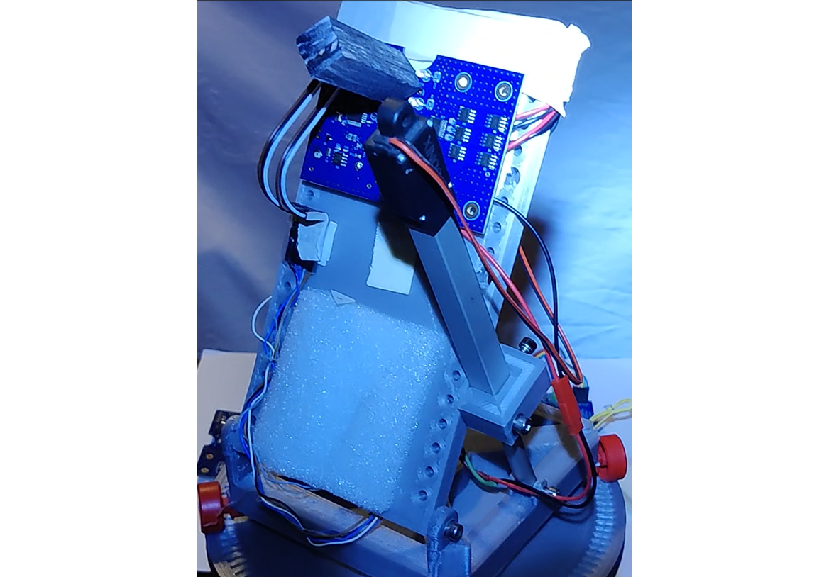
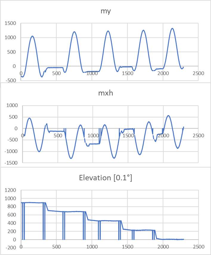
    PCBWay promised to try and send me the 25 new boards before Christmas. They would have been faster but my package with parts got stuck in the mail (Corona-Lockdowns...). To make use of the time, I tested a board with the new sensors on my desktop tracker. The MMC5603 magnetometer is better than the MPU9250 but the MXC4005XC accelerometer is noisier. I am now applying 20x oversampling to both devices in parallel with good results. The calibration routine ran through smoothly and the tracker behaves as expected. Below you can see the readings of the magnetic my component and the mx_horizontal component which is composed of mx and mz.

    As you may see from the readings, the tracker is doing full azimuth sweeps starting at 90° elevation and going down to 0° elevation in 4 steps. 

    This is the final proof that we chose suitable components.

    Once the new boards arrive I will have to figure out the programmer board which uploads the code and which should also do a quick test of all functions to make sure that the tracker board is working properly. 

  • Pogo board files are public

    Ruediger F. Loeckenhoff10/30/2022 at 19:30 0 comments

    The Pogo test board files (Eagle) have been published under MIT license as Pogo_board.zip.

  • Further strategy

    Ruediger F. Loeckenhoff10/30/2022 at 04:59 0 comments

    I just ordered 15 pogo pin boards and I ordered all necessary components a few days before. All parts arrived already. So I will be ready to go to build up the first pogo boards and test the tracker boards, once the delivery from PCBWay arrives. I liked the option that allowed me to combine shipping with the order for the assembled boards that I placed before. That spares me a lot of shipping cost.

    Ermanno will come to Germany for the Electronica fair and I will meet him for the very first time. Isn't that funny, considering that we have spent so much time together in Skype figuring out the right parts and arrangements?

    In any case, on our way to Munich, we will have a lot of time to discuss the further strategy of how to push this board into the Arduino and RasPi community as a standard part to consider. Offering it for a share of the cost and possibly also at PCBWay is a start. But these will only be a few parts to be sold and we will have to test them all. This is not our final goal yet. We need to find a company that decides to make them in quantity and promote them in their shop (maybe with a label: winner of the 2020 hackaday price). Once that happens, the board may be picked up by rebuilders and we are where I wanted to be from the start: 

    A unviversal solar tracker controller will be widely available

  • Test board ready for ordering

    Ruediger F. Loeckenhoff10/27/2022 at 13:16 0 comments

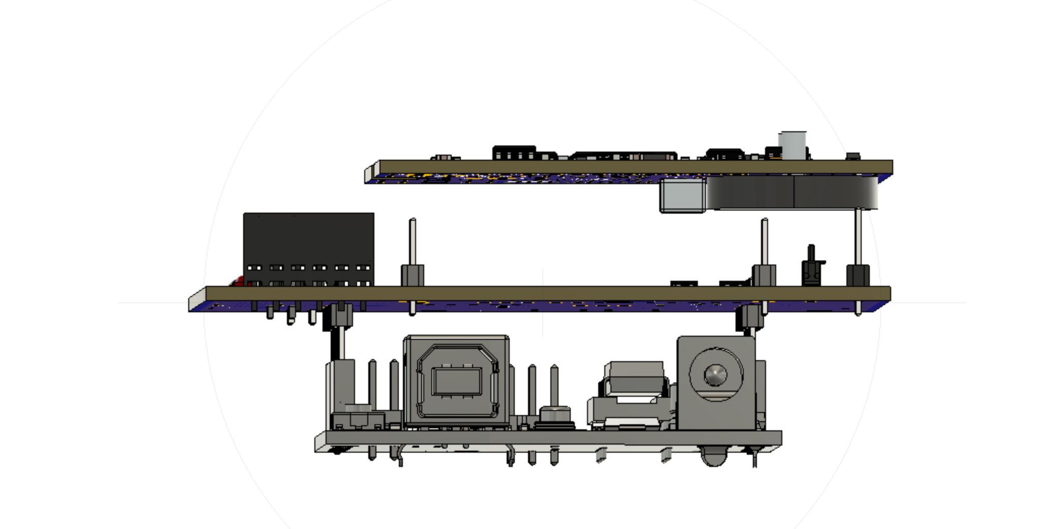
    After several discussions with Ermanno he finished the design of the test board with pogo pins that will serve for ICSP programming and testing of all components of the tracker board. In the figure below you can see the test board in the middle. It is mounted as a shield on top of an Arduino Uno and the tracker board is pushed backside down onto pogo pins (pogo pins not shown). The Arduino UNO can either serve as an ISCP programmer or as a test platform. 

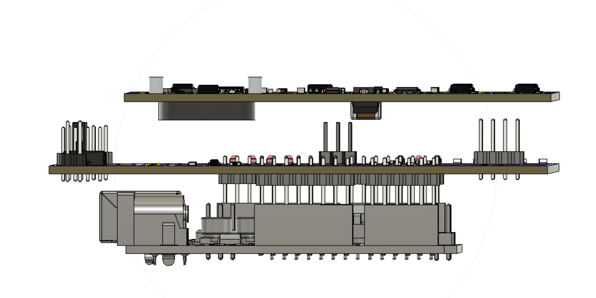
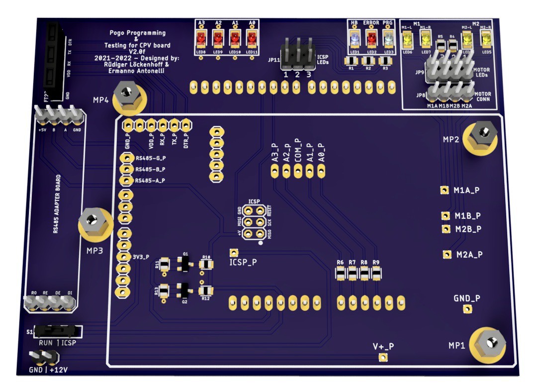
    And here is a rendering of the populated tracker board. 

    The positions that will get pogo pins are marked with a _P in the silk screen. The RS485 adapter will be on the left with the voltage selection switch (Run / ICSP) underneath. The four LEDs on the upper left side should only come on when there is something wrong with the sun sensor. They are a protection for the tracker board when we are applying 5V through a resistor to test the analog input. 

    Then there are the ICSP status LEDs on the upper right. Finally the motor output with status LEDs is in the upper right corner. The tracker board is pused onto 3mm screws and fixed with nuts to make it push down against the pogo pins.

    A full test will probably include the following steps:

    1) Upload bootloader and test program via ICSP.

    2) Change voltage to 3.3V and power up all 3.3V hardware by swapping a switch. Connect 12V supply.

    3) Run a test programm to check compass chips, RTC, photodiode tracking sensor, motor controll (all directions), motor current measurement, RS485 communication between tracker board and UNO.

    4) Calibrate z axis of the accelerometer by swapping the assembly upside down. Store the results in the EEPROM.

    5) Use FTDI adapter to upload the tracker program and check that the bootloader is working.

    With these steps, the tracker is ready for shipping. Since we must reprogram the UNO between 1) and 2), we will probably do 1) for a couple of boards and go on with 3)-5). We will need some of those QC stickers too, to make it look professional. 

    Ermanno will upload the board to PCBWay and we will see whether it processes correctly. I will order a few boards then to build up at least two test rigs.

    As soon as PCBWay confirms that the CAM files processed correctly, we will upload them here as open source (MIT license). 

  • Greetings from Ermanno

    Ruediger F. Loeckenhoff10/23/2022 at 13:18 0 comments

    Hi Everyone, Ermanno here. 

    I'm thrilled to be part of this project with Rüdiger being the scenes. I have contributed to the electronics design and PCB miniaturisation. All things consider, we managed to pack a lot of features in such a small board. Working with Rudi we pushed the concept of doing more with less even further and I think we succeeded. Now working on the test gig for mass production. If you look at the open source files, most of components are either Eagle standard libraries os sourced via SamacSys plugin. refer to the note in the schematics for any component question and feel free to give us a shout.

    All the Best,

    Ermanno

  • *** Uff - A busy week ***

    Ruediger F. Loeckenhoff10/23/2022 at 07:46 0 comments

    Uff, that was a busy week. My regular work, handling the orders at PCBWay, having long Skype discussions with Ermanno about the best test scheme and polishing up the project site for the contest. In particular, I realized that my video was 6:30 min and only 5:00 min were allowed. I's 4:58 now. Forgive me the somewhat strange cuts in some places. 

    Let me go through the checklist:

    i. Build a working prototype of your project.

    • Working prototype of STAGE1 (made from breakout boards)
    • Working prototype of V1 board that still required external breakout boards for the chip level sensors which were just not hand solderable. Please see the test documentation in the project logs.
    • Prototypes of V2.0f board are ordered but obiously we couldn't test them yet.

     ii. Create a video, between two (2) minutes and five (5) minutes in length:

    • It's 4:58 

    iii. Project Profile: On the Project Profile: 

     a. Link to the video 

    • Done and tested.

    b. Post high-resolution photos of the project inside and out 

    c. Update and add detail to info entered at the previous stage(s) 

    • Done

    d. Show at least ten (10) Project Log updates or at least ten (10) Build Instructions updates 

    • This is project log No 24 and I asked Ermanno to say hello in Log No 25 and prove that I didn't just invent him to simulate teamwork. We should be fine.

    e. Post a components list that is complete with a bill of materials for one unit 

     f. Post reproducible build instructions 

     g. Post complete schematics and documented input and output requirements and specifications for your module/design h. Publish all design files Including Gerber files (req – RS274 / RS274X), STL files (opt), netlist (opt), nc drill files (req – human readable), ODB++ (opt), STEP (opt), PCB files (opt), or any other design files

    I's all there and I feel good about it. I guess we reached a fair level of openness. All publications are under MIT license and we promise to add the test board design and operating instructions for the V2.0f board once everything is working. I may also invest time into the adaptation of this board to robotics (I2C slave) but I cannot promise that yet. It would be great if a 3rd team member (or more) could take over that job. And then it all depends on finding a community and a company that will use the board for solar tracking on large scale.

  • Working files released

    Ruediger F. Loeckenhoff10/23/2022 at 07:15 0 comments

    This was the first time for me that I ordered an electronics assembly so I think I may share my experience. 

    First of all, most of the credits should go to Ermanno Antonelli who spent hours and hours figuring out the component data sheets, designing the board and populating the components list. He generated a CAM output in Eagle and a BOM list in Excel. 

    At PCBWay you have to make two orders - one for the boards and one for the assembly. I already had some ATMEGA328pb-au and also the RS485 chip which is not so available right now. So we chose the option where most parts are sourced by PCBWay and some are provided by us. Unfortunately, the TVS diode is not available to PCBWay and I didn't order it yet. So I will have to solder it myself. But that's easy. It is a big part on the back side.

    Ermanno then uploaded the CAM files and the BOM as an Excel file. PCBWay wanted a certain format, so better use their template from the start, if you plan to order there. The layout was processed by PCBWay and cleared. I received an updated version of the BOM where PCBWay had marked components that had to be replaced and suggested alternat versions. In some cases it was just a difference in the format of the serial number. I had to answer in another column of the table and yet received an updated version from PCBWay for a final approval. The BOM issue was handled in a very effective and professional way.

    With this settled, the final price for the assembly was calculated and I had to pay - with a generous sponsoring from PCBWay who like this project. We will offer boards for a share of the total costs including shipping and parts provided by us. This will amount to a total cost share of $40.

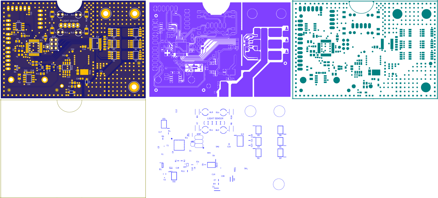
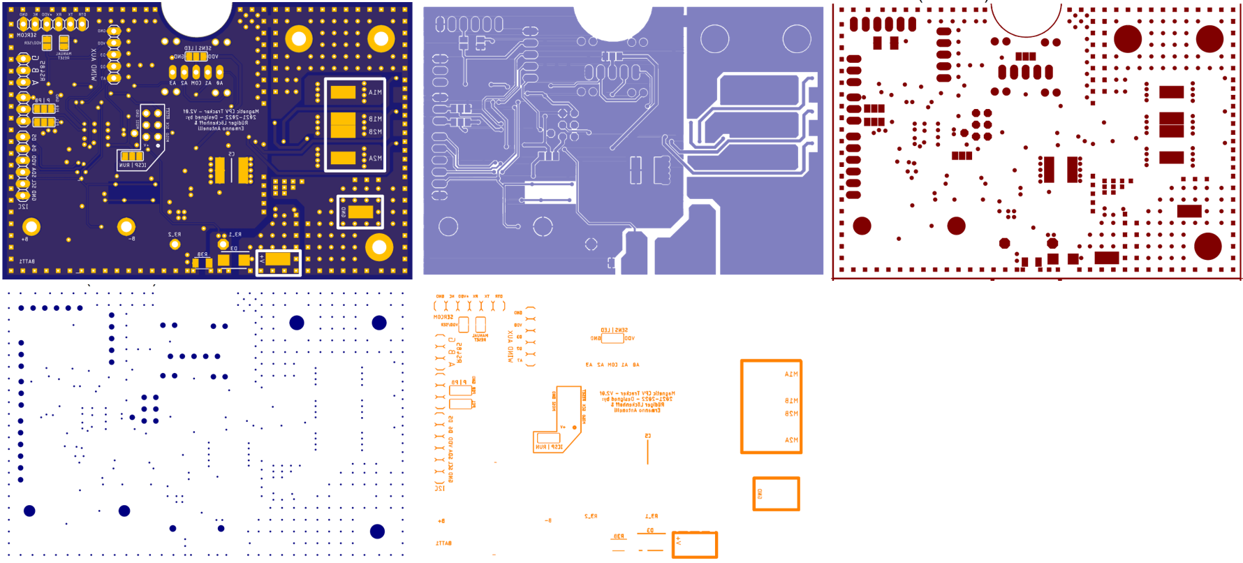
    Finally I received the working file plots from PCBWay. I wonder whether PCBWay will allow me to make them public too. I will ask.

    In any case I copied them all to powerpoint and compared them to the renderings of the board that Ermanno had sent me. They all matched. You will find the printouts below.

    Ordering PCB Assemblies is actually not so hard - if you have Ermanno to prepare the files for you. 

  • Don't forget about testing!

    Ruediger F. Loeckenhoff10/21/2022 at 15:28 0 comments

    If we want to get close to a professional product we need a testing scheme. This would not be necessary for the 25 boards we ordered now, but for a mass production by a major assembly company. This is our goal, after all and there is no reason, not to do it right from the start.

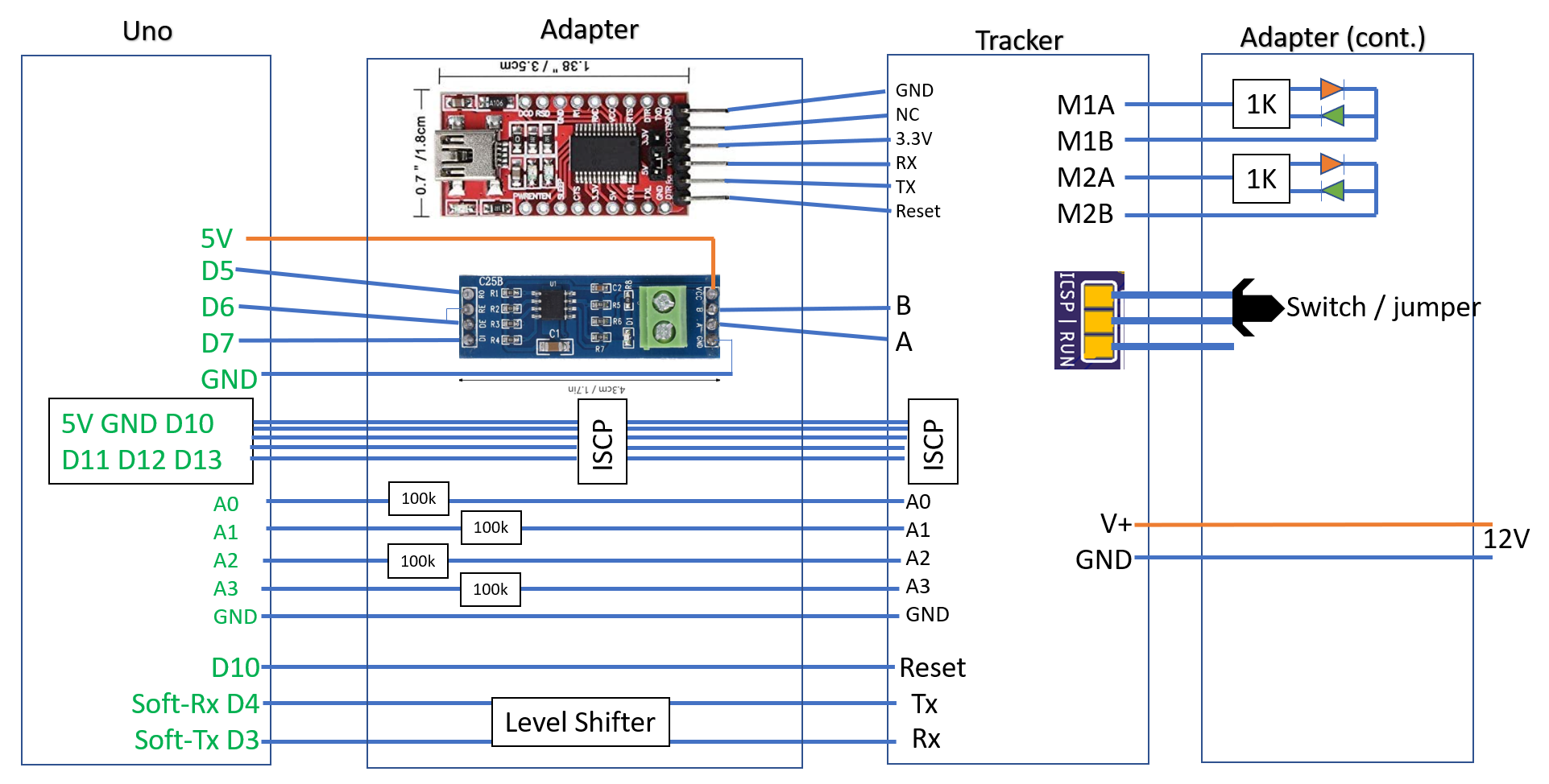
    Even for just uploading the bootloader and code, we need a board with pogo pins. An Arduino Uno will serve as an “Arduino as ISP”. Since we will have that board already, it should also do the testing. My idea is, that the Arduino Uno should handle the serial interface of the tracker board and go through the first calibration steps. If all serial responses of the tracker are correct, it is obviously working.

    The functional test should include the sun sensor and the motor control. In the third calibration step, the tracker follows the sun with the tracking sensor. We can simulate a tracking signal by sending a small current to the photocells. As a result, the motors should start running and the current sensing should sense the motor currents in all directions.

    All serial communication between the tracker and the UNO (soft serial) will be mirrored through the native serial port of the UNO to the computer. Furthermore there is a max485 adapter on the board to test the RS485 communication.

    Setting up the full test program will take time. Therefore, we also include an FTDI USB Serial Adapter to address the tracker board directly from the computer. 

    This arrangement should make uploading and testing easy. You can see my scheme below and yesterday evening I had a long session with Ermanno to discuss the schematic and board layout. He is great.

View all 31 project logs

  • 1
    Step 1

    For the assembly instructions of the Open CPV Solar Tracker Controller based on breakout boards see assembly and operating instructions in 2021_08_14_Full_description.pdf.

    The Assembly of the all in one board "Magnetic CPV Tracker v2 0f" should be done by a professional assembly company. You will find all required files for ordering at:

    Magnetic_CPV_Tracker_v2_0f_Eagle_CAD_CAM_BOM_documentation.zip

     A detailed assembly and operation manual as well as the final design of the pogo pin test board will follow. The remaining assembly steps for an waterproof unit will be:

    1. Prepare an aluminum plate with a shading beam and through holes for the LED photo diodes.
    2. Test the board or get one of the tested boards from us.
    3. Mount the board on the aluminum plate with silicone as heat transfer agent and encapsulant.
    4. Connect the wires to the 12-36V DC supply, motors and RS485 communication.
    5. Cover it all with silicone to get a hermetic package without air inclusions.

    The operation of Magnetic CPV Tracker v2 0f will be very similar to the breakout board version so refer to 2021_08_14_Full_description.pdf for a preview.

View all instructions

Enjoy this project?

Share

Discussions

ErmannoAntonelli wrote 10/23/2022 at 12:57 point

Hi Everyone, Ermanno here. 

I'm thrilled to be part of this project with Rüdiger being the scenes. I have contributed to the electronics design and PCB miniaturisation. All things consider, we managed to packed a lot of features in such a small board. Working with Rudi we pushed the concept of doing more with less even further and I think we succeeded. Now working on the test gig for mass production. If you look at the open source files, most of components are either Eagle standard libraries os sourced via SamacSys plugin. refer to the note in the schematics for any component question and feel free to give us a shout.

All the Best,

Ermanno

  Are you sure? yes | no

leo.stelzer wrote 10/09/2022 at 19:48 point

Hello Rüdiger,

I am trying to build a micro pv power plant (Balkonkraftwerk) for 800Wp max. with dual axis suntracking. I figure by your name and location that you speak german too. I tripped over your project because I am looking for the best way to control the suntracking. I did build a little model with a 50Wp panel and suntracking with photoresistors. This little thing works fine with bright sunlight but dosen’t perform well in cloudy situations. For my next project I am looking for a more robust control that is not freaking out when the weather is less favorible. Do you already have a working prototype of your controller? I am trying to send you a sketch of my project but it dosen't seem to work in this post.    Best regards   Leo

  Are you sure? yes | no

Ruediger F. Loeckenhoff wrote 10/09/2022 at 20:57 point

Hello Leo, this is exactly what we are developing our board for. Please follow the link to the video and you will see that there is a working prototype made from breakout boards.

https://www.youtube.com/watch?v=9LZE1shnXd8

The firmware is pretty far advanced. I would love to have you as a beta tester to tell me where I need to improve the manual. Follow my links to GitHub and you will find the source code there. We also have a working prototype of an ATMEGA328 board with MXC4005 und MMC5603 6 axis compass. These tiny parts are almost impossible to hand solder, so we needed to attach breakout boards leaving the spaces for these chips on the board unoccupied. The real time clock and RS485 communication are already on board. Right now we are having 50 pcs made and we can give them away for $25 a piece on a reduced rate thanks to a sponsoring through PCBWay who will do the assembly for us.

Thank you for your images, I will put them into a project log.

  Are you sure? yes | no

Ruediger F. Loeckenhoff wrote 05/08/2022 at 19:22 point

I feel that I should add some more to my answer because it might have a somewhat frustrated undertone. We are working so hard to make CPV big scale reality and we are constantly so close to just making it. We already achieve a much higher efficiency than silicone flat plate PV and if we got the chance to move down the learning curve we would quickly be better in terms of Cent/kWh. This is basically a no brainer because the efficiency is higher and the material consumption is lower. I guess up until now we were just too slow and we let the flat plate industry run away. Yet I strongly believe that we can still catch up. We all had our learning curves on the side of CPV solar cell and CPV solar system development and I believe we came up with great products. Yet there is more too be done and I believe that the tracker controller is the lowest hanging fruit. With the “credit card sized board” we have moved 80% of the way in terms of cost reduction and I hope that this will help and give confidence in other fields such as solar tracker development. Putting CPV solar modules onto a tracker requires unnecessary material for the frame so the tracker and the module need to be integrated. This is actually another relatively low hanging fruit. Valldoreix Green Power has shown how this works. Getting rid of the foundation is yet another topic. I have shown one option with the three wheeled tracker with a winch. I believe this solution can be very cost effective, reliable and easy to repair. Yet there will be other options – show them to me!

In terms of the modules automatic assembly is the key. That requires investments and the first automatic production line requires a lot of development. A multiple replication of that line comes much cheaper. Then these lines need to run 24/7 to pay for themselves.
If you buy low quantities you are restricted to the most common materials and processes. If you can buy large you can get exactly what you need from one place at a low price without shipping stuff around.
… I got carried away. In the end there is one point I want to make:
Soitec has proven that CPV works and can be very cost efficient and reliable. Unfortunately, they were let down by there partners in the worst possible moment after having built up three production lines and the projects these lines were built up for where suddenly cancelled. That was a great tragedy.

If you do CPV right and you have enough financial impact to get good prices for the raw materials and you do have the projects to pay for the investments in fully automatic production lines, then CPV can quickly become one of the most important contributions to the energy transition – in particular in combination with storage. Fusion Fuel and RayGen seem to be on a very good way and I have great hopes that they will make it.

 
The great thrill of CPV for hackers is the chance to really contribute to the development. There is no chance to make a better solar cell in your garage, but you can make a better solar tracker if you have just the right idea. And this may then become a standard solution. Wouldn’t that be cool?

  Are you sure? yes | no

Ruediger F. Loeckenhoff wrote 05/08/2022 at 06:37 point

Written in Word, copied to the chat, formatting messed up.

  Are you sure? yes | no

Ruediger F. Loeckenhoff wrote 05/08/2022 at 06:33 point

Hi James,


Wow, you are asking the hard questions. In the residential scale CPV solar tracking is for enthusiasts. You might
buy some Soitec CX-M400, build up the tracker mechanics on your garage roof – and preferably come up with a new or refined solution, to contribute to the development buy the few components that my electronic circuit requires or – when we are done – buy our circuit board make it work and adjust the modules
Now wait for your friends to come by and show them a really cool gadget that even saves you 25% of your electricity costs.

This is hackaday after all. I believe this would be great fun for many. Because it is so visible. Cooler than a Tesla, because there are so many around already. And if you already do have a Tesla, you can charge it with CPV.

Now, these are my hopes why “you guys here” will get involved.

The next part of the question is about the economic chances of CPV. If we do have a chance, it is in solar plant scale. If you look at the components involved and the efficiencies we achieve (45% cell level, 33% module level, low thermal coefficients) we should be very well able to compete. After all those silicone flat plate PV guys need to cover the whole area with the same kind of material that microprocessors are made of. Insane, isn’t it? Unfortunately (or fortunately from an ecologic point of view) they are so far advanced that scale more than evens out these disadvantages. Fortunately – for us – there are niche markets to get started. Fusion Fuel uses the heat of the CPV receivers to make hydrogen electrolysis more efficient. And hydrogen will likely be a real megatrend. RayGen uses the heat of their big receiver to feed it into a storage system that involves heat pumps and rancine cycle turbines between huge hot/cold water basins. That’s really thermodynamics at its best.

In both cases, the advantages of CPV come together with heat – from the CPV receiver – and storage.

Yet, clearly CPV needs to advance or it will become irrelevant. This project is meant to be such an advance since it reduces a control box that may cost several hundred $ to a single printed circuit board that may be “extremely cost effective” with only a few non-expensive parts involved.

Yet I have to face the possibility that my work on CPV may not contribute to the energy transition. In that case this control board is also the most effective way to run a PV solar tracker. This may be one axis or two axis. In the latter case you don’t even need a sun sensor because gravity is pretty reliable (as any toddler struggles hard to find out). I.e. you can run a one axis tracker on a 3-axis accelerometer alone with high precision and there should be a cost-effective board made for Arduino code for this purpose.

Finally, there may be other applications for this board. It has a magnetic compass, an accelerometer and a 3-half bridge motor controller as well as an RTC. More I2C devices can be connected externally. For instance, you have a single Arduino-compatible board with a powerful three phase motor driver. Doesn’t that call for hacks?

If you are one of the enthusiasts that wants to show off with a CPV solar tracker on his garage roof, let me know and we can discuss solutions.

All the best

Ruediger                                                                           

  Are you sure? yes | no

James Newton wrote 05/07/2022 at 23:00 point

Do you have any public sources for these CPV type panels? And for the tracking mounts? What I can find for those so far appear to be very very expensive, and don't seem to justify the extra cost vs the energy produced. E.g. unless the size of the installation is the limiting factor, it would seem to be better to just buy more of the lower cost, non-moving, standard solar panels and spread them out over a larger area. I'm assuming this solution is targeted at installations where the space IS constrained, although I'm not sure I can think of a valid example... Perhaps this system would allow someone renting an apartment or condo to run internal lights off their balcony? Or perhaps for camping / wilderness survival where the weight might be less?

  Are you sure? yes | no

Similar Projects

Does this project spark your interest?

Become a member to follow this project and never miss any updates