 Ruediger F. Loeckenhoff
Motor controller and current measurement
This will be a long log, so I want to summarize: The motor controller of the “single board” works as expected and we can get a current measurement which is good enough to detect blocked or damaged gears and motors. We can transfer these readings to a central field management computer via RS485.
Adjusting and checking the PWM
I had 3.9 kHz at 16 MHz clock speed for the open source tracker. So, I expected this to reduce to 1.95 kHz at 8 MHz clock speed. My expectation was correct.
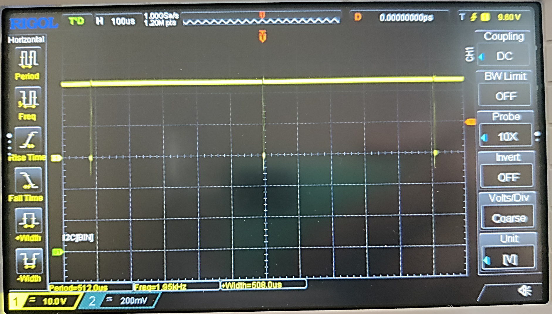
This is full speed. We are using a DRV8300 bootstrap driver and the small dips are necessary to recharge the bootstrap diodes. Without these dips, the driving voltage of the upper FETs in the half bridges would collapse.
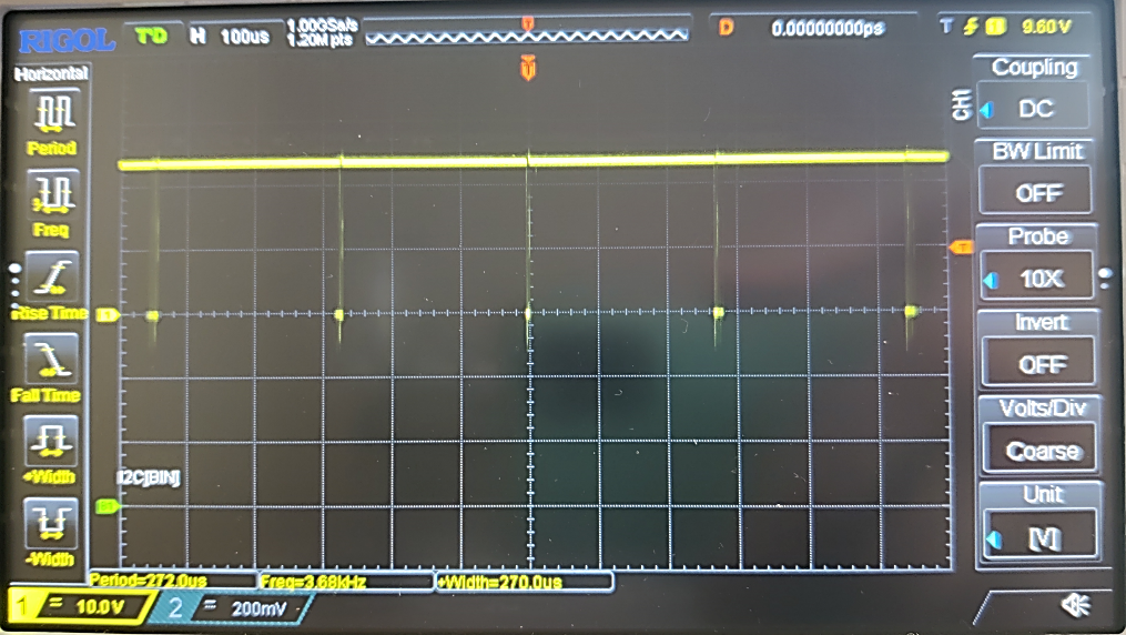
Now, I wanted to increase the PWM frequency to 3.9 kHz again by adjusting the timer pre-scalers for the PWM timer (I am using timer 1). This almost worked out. I guess, I am losing some time somewhere in the interrupts. 3.68 kHz is good enough.
Motor speeds can be chosen from 1 to 16, where 16 is full speed as seen above. Now I tried speeds 1, 8 and 15. Everything works as expected.
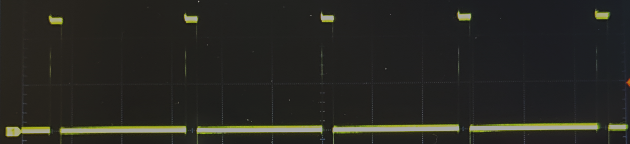

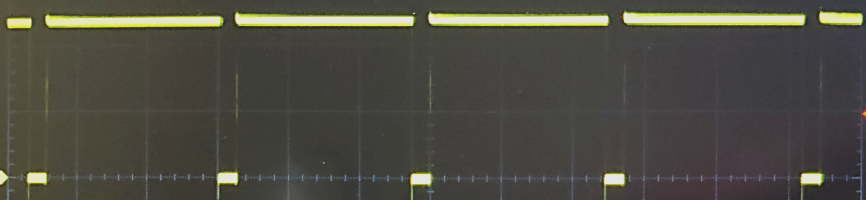
Perfect! Well done, Ermanno (who figured out the DRV8300).
Now I should explain, how we are doing the current measurement. Please have a look at the schematic below.
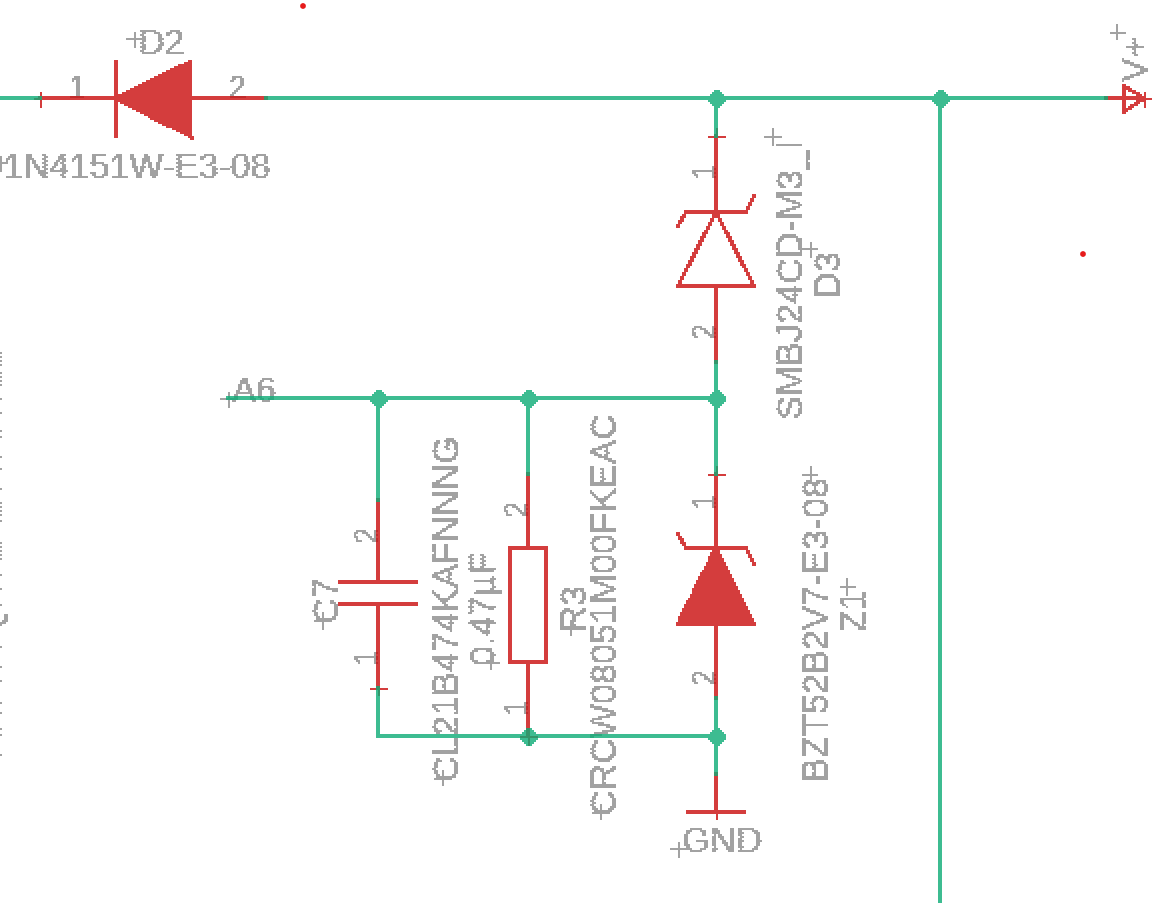
The current is coming in from the right at e.g. 24V. The power supply and the cable are inductive. On the other side, the circuit is drawing power in pulses, especially as far as the motor controller is concerned. When current through an inductivity is interrupted, a high voltage pulse is generated. We don’t want that, because it can fry the MOS-FETs. So we either need to use an input capacitor or an overvoltage surge protection diode. We decided for the latter. It is basically a 26V Z-Diode (SMBJ…). It will absorb voltage spikes and thus we loose a tiny amount of power.
Now, it’s not a bug, it’s a feature! We yet need motor current monitoring. So let’s measure the spillover current through the Arduino Analog ports. This yet requires a measurement shunt an a filtering capacitor as well as another Z-Diode (BZ…) to protect the analog input ports.
Now that’s unconventional. Will it work?
First I want to show you the following graph:
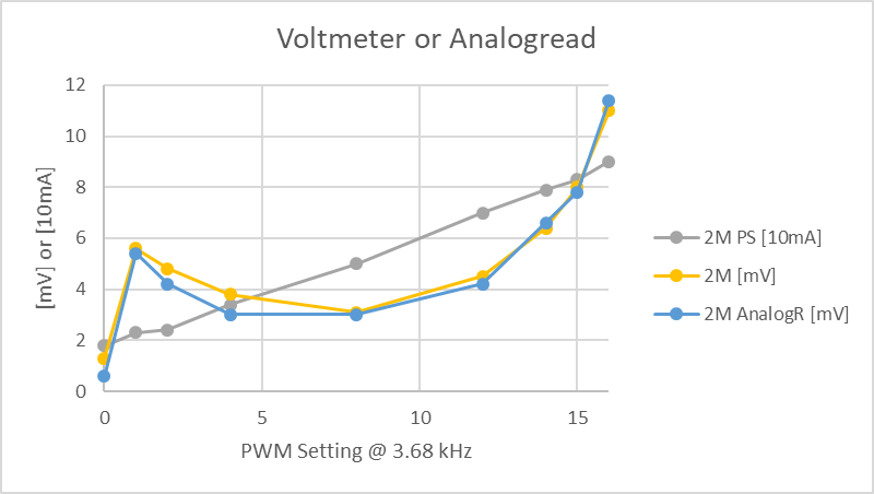
“2M PS [10 mA]” is the power consumed by the whole circuit which I read from the power supply. 2 motors “2M” are connected to one output to give me a bit more power consumption. The circuit without motors running consumes 18 mA which corresponds to “1.8” in the graph. Now I sped up the motor by increasing the PWM duty cycle from 1 to 16. The power from the supply increases more or less linearly. “2M [mV]” is the voltage at the 0.47µF capacitor read with a voltmeter. This corresponds to “2M AnalogR [mV]” which is the value obtained through the analog port with 10 bit ADC and an internal reference voltage of 1200 mV. 1100 mV is standard and 1200 mV is still in the allowed range for the ATMEGA328. Yet I rather guess that the measurement error is caused by the impedance of the voltmeter when I measure mV by hand. When I try to stop the motors, the analogRead value increases a bit.
First Conclusion: it kind of works!
Yet the shape is a bit strange. Let us compare the mV reading for single load (1 motor) and double load (2 motors).
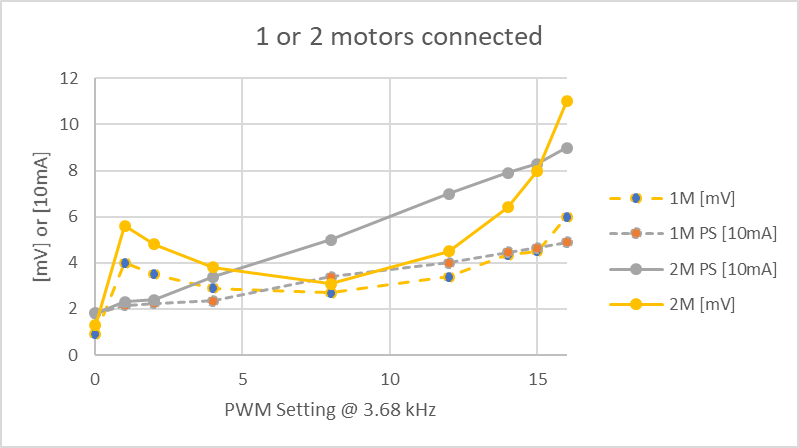
So when two motors are connected, the reading at the 0.47 µF capacitor increases at any PWM duty cycle. That’s good, that’s expected!
Now, here comes the surprise. This is the comparison between no motors and 2 motors connected.
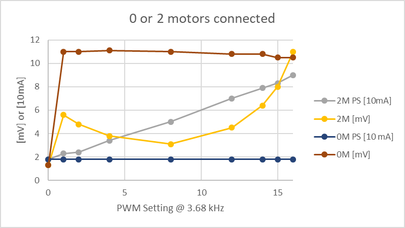
Apparently, the bootstrap driver generates spikes when no motor is connected and thus we read 11 mV at the capacitor even when no current is drawn from the motors. This doesn't mean that we would see a higher consumption at the power supply.
Now, please note that I used tiny motors for testing which draw 25 mA at full speed. So, realistically, the current in the field will be 100 times as high, i.e. in the range of 2.5A. The voltage signal of the motor will be in the range of 500 mV. The 10 mV signal from the bootstrap driver will not matter much anymore. I need to find a bigger motor. The maximum reading at the capacitor is limited by the 2.7V Z diode which protects the Arduino analog port. If 500 mV is 2.5A, then 2.5V at the Analog input would be 12.5A. This is more than our 8A FETs can handle. I guess, the current monitoring is amazingly well adjusted. If we yet wanted to change it, we just need to swap the 1 MOhm resistor in the schematic by some other value.
Discussions
Become a Hackaday.io Member
Create an account to leave a comment. Already have an account? Log In.