A very quick update, with a new motherboard design.

The concept with Iteration 8 is to have a science-tricorder-like device that fits on the back of a smartphone. The central challenges have been figuring out how to interface high-bandwidth sensors (like the thermal camera and high-speed magnetic field camera tile) to phones that generally aren't able to easily have external input -- and more specifically, to do this with an iPhone like the one I carry around (it takes beautiful pictures, and has about 5,000 of my very loved 17-month old on it right now). The compounding difficulties are that being on the tenure track with a little one, I have essentially no time, and my first design for an Iteration 8 motherboard was completely off-base, being quite large, and having a number of design errors and oversights (as prototypes do). It incorporated an Arduino Pro Mini for easily interfacing with the low-bandwith sensors, and a Raspberry Pi Zero for interfacing with the high-bandwidth sensors (and, communicating with the phone over WiFi) -- but it turned out pairing these two together with the Raspbery Pi programming the Arduino was very cumbersome, and the Pi Zero appears far too underpowered to run a responsive X-windows GUI, let alone develop the software for the Arduino on it. The SD card on the Pi was corrupted from the unsafe powerdowns associated with a development environment enough to be very prohibitive to development. But I think the general idea of connecting the two together is solid, so I decided to take another pass.

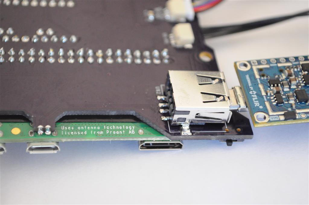
I decided I was overthinking the motherboard design -- trying to have all the features on it from the first pass, rather than having something simple that just worked, and progressively iterating new features with it. Enter the new motherboard design above -- it includes:
- A Raspberry Pi Zero W (for the FLIR thermal camera, and magnetic imaging tile)
- An Arduino Pro Mini, for the rest of the sensors
- A pre-built lithium polymer charger and 5V booster (for the Pi/USB voltage). The 3.3V is supplied from the Pi, rather than from a secondary converter.
- A single USB port for the thermal camera, rather than the full 4-port hub I included in the last design.
- An assortment of JST connectors for connecting sensors, including several QWIIC I2C connectors.
And that's pretty much it! Intelligent power saving? Not in this version, with the exception of a single manual switch on the USB connector to enable/disable the thermal camera (which can consume a lot of current). Other than that, the whole thing basically consumes plenty of current all the time to keep it's ~2000mah battery warm. But a lot of my mental effort has went to figuring out how to add enough power saving features to have this design powered for approximately 24 hours straight, which is rather challenging given the power requirements of the Pi Zero, so I decided to just continue on without power saving features in this iteration, and focus on getting something working end-to-end.

To keep the height profile small, the Pi Zero is soldered directly onto the motherboard. The USB is connected using the same clever mechanism of the ZeroStem, which uses two castellated throughholes to solder directly onto the USB data test points on the bottom of the Pi Zero. Simple, clever, and appears to work well so far!

I've connected a number of sensors to the design so far, including the above two atmospheric sensors from Sensirion. The SPS30 Particulate Matter Sensor (left) detects the distribution of particulate matter in the air, while the SCD30 CO2 Sensor optically measures atmospheric CO2 levels, while also measuring temperature and humidity. I had included a VOC sensor, but I have questions about the accuracy of the measurements, so I'll set that aside for the moment. Both sensors connect using I2C, which makes connection very easy.

The Radiation Watch Type 5 sensor is also included, with my external comparator backpack for being able to tune the detection threshhold from it's factory calibrated value of ~60keV down much closer to the noise floor. Using this method, I'm able to observe substantially more detections from the Ba133 radioisotope source used in the Open Source Computed Tomography Scanner, which has a large spike in emissions around 31 keV.
Above is the external comparator backpack for the Radiation Watch Type 5, with the JST connector and cable to the motherboard.

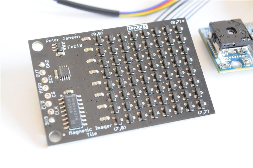
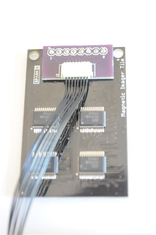
My high-speed magnetic tile imager can be driven quite slowly for low framerates, but the really interesting stuff happens when you start observing fast-moving magnetic fields at 1000+ frames per second. That requires a fairly high-speed analog-to-digital converter, and (more importantly) more RAM than most microcontrollers have if you want to record more than a second or two of video, so this sensor is connected to the Pi.

Though I haven't yet worked to get this working with the Pi Zero, I added a small JST connector to the back of this board that connects directly to the motherboard through a short cable. It exposes the SPI port and several GPIO pins from the Pi that should (hopefully) be plenty fast to drive this sensor. I prefer accessing low-level sensors from low-level devices (like microcontrollers), so I haven't yet put this driver together to test this configuration -- hopefully soon!
That's all for this quick update -- thanks for reading!
 peter jansen
Discussions
Become a Hackaday.io Member
Create an account to leave a comment. Already have an account? Log In.