 peter jansen
A quick update with a new high-speed version of the magnetic imaging tile!
I've been very interested in visualizing things that are very difficult for us to normally see for a long while -- it absolutely fascinates me that there's so much around us that we just can't easily perceive, and I often wonder how much more we'd be able to understand about our worlds, and how much more interesting bits of science we'd be able to get done, if only we could easily see them as naturally as we see things like colour.
One of the most memorable examples of this, for me, is a little more than a decade ago when I'd literally just assembled my open source science tricorder mark 1, turned it on for the first time, and started wandering around the room to see what interesting things it might detect. A moment later I'd stumbled upon a power adapter plugged into the wall with a transformer, and the oscillating field inside being detected by the magnetometer. That magnetometer and visualization was updating at only a few cycles per second, much slower than the 60Hz oscillations inside the transformer, but it was enough for me to watch that aliased oscillating magnetic field vector make large swings back and forth, and make me wonder what it would look like if only we could see it hundreds of times faster, and with an image instead of just a single vector. Magnetic field visualization also seemed much like low-lying fruit -- we've been very good at producing very low cost, accurate magnetic field sensors for a long time, so this seemed possible in the near term.
I can't say things happened as quickly as I'd hoped, or even that I was able to form an idea for what a magnetic imager might look like that evening. But years later I ended up becoming fascinated with magnetic resonance imaging (MRI), and tried to dream up an idea of what an inexpensive desktop MRI might look like. One of the difficulties with MRI is that it requires very homogeneous magnetic fields to be placed over a sample, in order to spatially resolve different parts of the sample (and render an image). The normal way this is done is with a large, beautifully homogeneous, incredibly expensive superconducting magnet, but I had wanted to figure out a way to do it with a terrible, not super homogeneous, cheap electromagnet by reading all the field variations, and calibrating them out -- and I had decided to try to do this by creating a first magnetic imaging tile built out of a lot of 3-axis magnetometers in a 10mm grid. That low-field MRI project stalled a bit (it turns out being a tenure-track professor takes a lot of your time), and along the way I was able to create a two much simpler (but incredibly slow, incredibly low resolution) desktop computed tomography (CT) scanners, but the idea of creating a magnetic imager for it's own sake (apart from the idea of building a low-field MRI) seemed very clear. I put together an array of Hall Effect sensors that (unfortunately) lose the 3-axis vectors of many magnetometers, but have very fast updates, and built the Magnetic Imaging Tile V2. That tile was very cool -- for the first time I had an imager with a reasonable spatial resolution (~4mm) and a large number of pixels (12x12, though I had only ever populated a smaller ~8x8 subsection). But unfortunately my design choice of using an I2C I/O multiplexer for addressing each "pixel" (magnetometer) in the tile meant that it was limited to a framerate of about 10-30Hz. This meant I could see very neat static fields live, but placing a transformer near the tile only showed it rapidly oscillating and unable to render a good image, because the tile was about a hundred times slower than it needed to be to sample such a fast field.
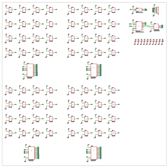
The schematic for the new V3 tile is shown above (click here for a PDF).
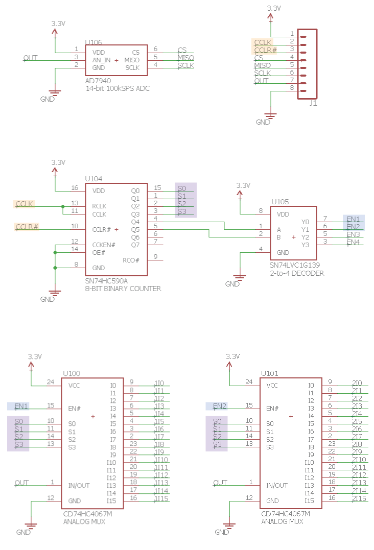
One of the critical issues I had was how to resolve was how to make the tile addressing much faster, by replacing the I2C I/O multiplexer with something else, while keeping the external pin-count for whatever microcontroller would be interfacing with the tile still low. After a bit of brainstorming (and by this, I mean mostly doing other things for a long time until the answer suddenly came to me one day), it occurred to me that since we essentially need to move through each pixel only once per frame, and that the CD74HC4067M analog multiplexers have 4-bit binary addressing (with an active-low enable line each), the I2C I/O multiplexer could be replaced with a 6-bit binary counter, with the lower 4-bits for addressing a specific channel on each multiplexer, and the next 2-bits used for selecting which multiplexer was enabled (through a 2-to-4 decoder). Some 1970s-era 7400 series logic later (a 74HC590A 8-bit counter, and a 74LVC1G139 decoder), I had an addressing mechanism put together that still uses only 2 lines (a clock, and a reset back to 0 -- the first pixel), but can likely be clocked at some ridiculous speed -- in the megahertz, and far faster than any ADC that I have readily available (or, possibly, the response time of the magnetic field sensors themselves).
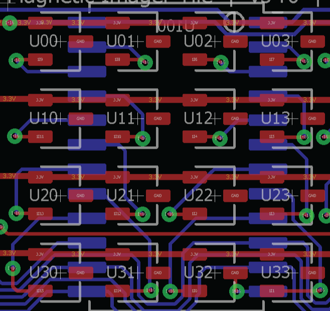
A quick note about the addressing, which is interesting. Though each analog MUX has 16-channels, for routing considerations it's not easily possible to build a system that iteratively addresses the pixels in straight lines, one after another. Instead, each analog MUX is responsible for a 4x4 array of magnetometer pixels, and still not in any easily recognizable pattern -- just a regular pattern that was (painstakingly) found to fit and be tile-able with a 2-layer board. It's a little challenging to route this, and while it looks complicated, a little bit of software in the form of a look-up table ensures that it's still possible to read each pixel's data and place it in the right spot in a framebuffer at a very high speed.
I also decided to go back to Eagle to do this, since they'd just advertised adding a push-and-shove router, and I wanted to test it out. I've been using Eagle for more than a decade, but had switched to KiCad for the push-and-shove router, and when Eagle switched to a subscription based license model (In spite of having purchased two previous versions of Eagle, I will never purchase subscription-based software). Still the free version brought me back, and it only took me 4 hours to route, versus two weeks of evenings and weekends with the KiCad router, which is mostly due to a combination of my being very new to it, and the usability issues that the KiCad folks are progressively ironing out with each iteration.
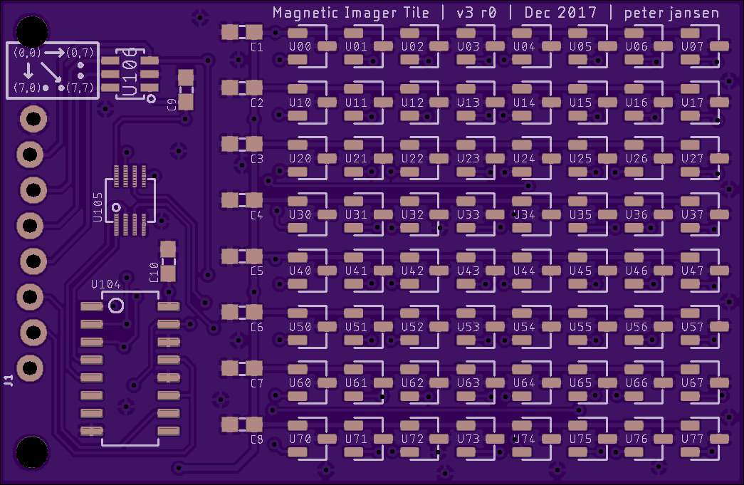
The tile itself is intended for Iteration 8 -- a sensor package that I'd like to place on the back of a phone, since it's way more powerful at visualization than any stand-alone system that I would be able to realistically design from scratch (in spite of how enjoyable it is to design such devices, like the Arducorder Mini). I've been tinkering away on this, very slowly, for about a year -- and the V2 tile, in addition to being unable to reach high framerates, is also a little too large to easily fit on the back of a phone while allowing room for other sensors to fit as well. So I decided to reduce the size from 12x12 to 8x8, since this made the tile physically much smaller (53 x 35 mm), and also much cheaper/easier to make.
The tile design itself only has 6 separate parts (1x binary counter, 1x decoder, 1x ADC, 4x Analog MUX, 10x 4.7uF 0603 capacitors, and 64x magnetometers). I actually used the internal ADC on the Chipkit MAX32 to achieve an even faster framerate (~2000 frames per second) than the onboard 14-bit 100KSps AD7940, but I include it so that the tile could be used with a host that doesn't have an ADC (like a Raspberry Pi). The ADC is actually very expensive (about $10 in quantity), so replacing this with a faster, less expensive 12-bit ADC might be a solid idea for a second revision.
While the fastest I've been able to achieve is 2000 Hz on the Chipkit MAX32, it's entirely possible that much higher framerates would be possible. I think the limiting factor is currently the ~20KHz bandwidth of the DRV5053VA magnetometers, meaning that 20KHz framerates might be possible with an ADC that has a greater than ~1.5MSPS sampling time. I'm not sure what fields one is likely to encounter will move this quickly, and a quick Google seems to show most magnetic imagers today having updates ranging from 1-1000Hz -- but it would still be very interesting to see. Even though the DRV5053VA is the most sensitive analog magnetometer I was able to find at this price point, my intuition is that most fields one is likely to encounter that are oscillating that fast may also be very low intensity, so having a higher sensitivity might be required. I would still love to do this with an array of very sensitive 3-axis magnetometers, if I was able to get the density and speed up, while keeping the cost low (which I haven't been able to find yet). But having 3-axis vector information for each pixel would allow for some incredible visualizations, similar to Ted Yapo's very cool manually translated single-magnetometer scanner and the great visualizations he's put together.
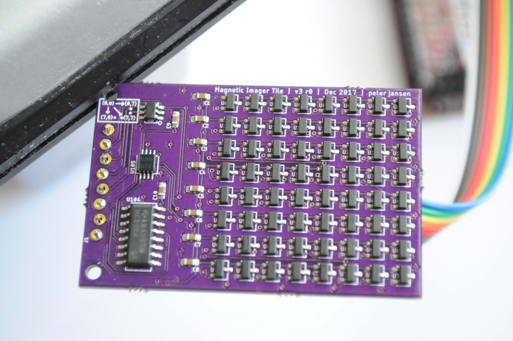
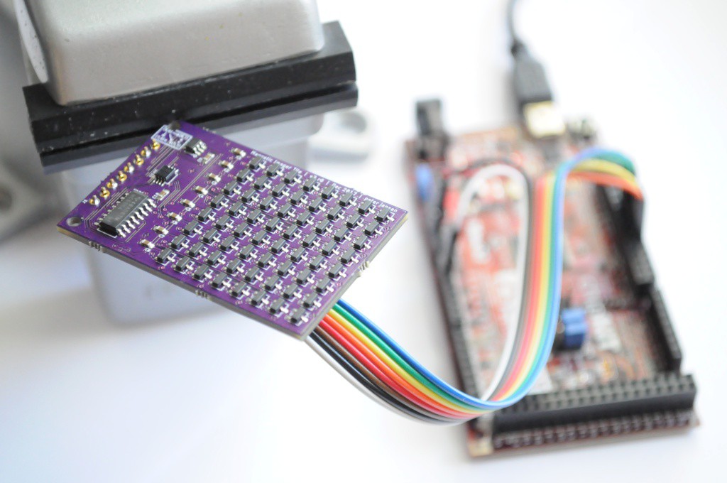
Here's a picture of the tile assembled. It took only about an hour to hand-place the parts with a tweezer after using an inexpensive stencil from OSH Stencils. I really enjoy the aesthetics of the tile -- seeing a large array of the sensors on the board. Theoretically the same method could be used for sensors of a variety of different modalities if they're available in the same package footprint.
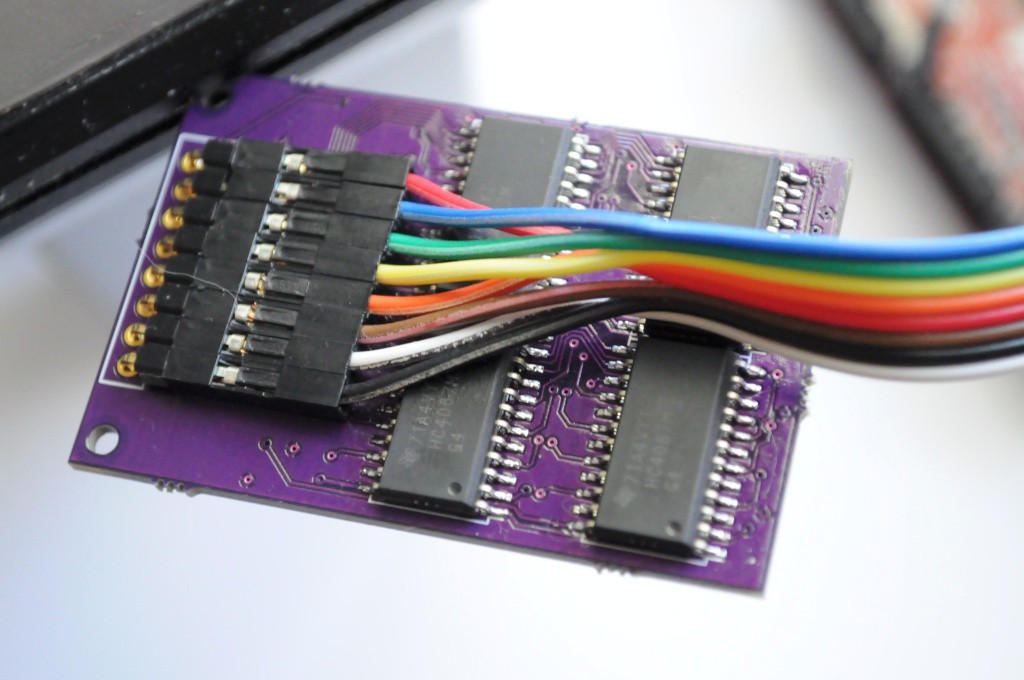
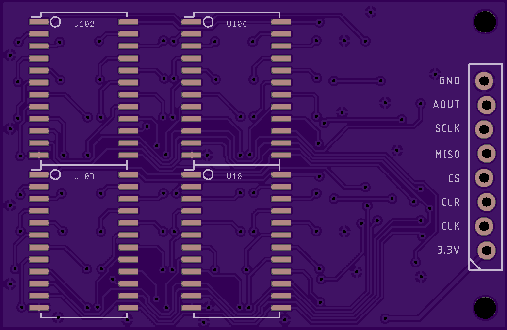
And the bottom of the board, with the analog multiplexers, and the connector. I had intended on using a locking pattern for the 0.1" header (since I'm still not sure what connector it will have to interface with whatever form Iteration 8 takes), but the locking pattern looked to be not quite offset enough (or the header I used was a little small), so I added a few dabs of solder. If another revision is made, this would also be a positive (and very small) change to make.
The source files for this version 3.0 of the magnetic imaging tile is currently available on the Gitub repository.
Thanks for reading!
Edit: SparkX has begun doing a small run of these to gauge interest. The product page is available here, with a few from the initial batch in stock, and more on the way in about a week. Please share pictures or videos of interesting applications or things you discover to scan!
Discussions
Become a Hackaday.io Member
Create an account to leave a comment. Already have an account? Log In.
Nice work, well done! Did you already know the TESLASCAN from Witschi Electronic?
( https://www.witschi.com/wp-content/uploads/2021/08/20210903_Witschi_Teslascan_Datenblatt.pdf )
I am working with this tool, the possibilities are huge!
But the device is for much lower magneticfields, -600uT zo +600uT.
Regards,
Joe
Are you sure? yes | no
Great work, well done.
Are you sure? yes | no
Hey Peter,
Love the project. I have a need for something like this for an electromagnetic coil pcb I am making. So hard to debug when I can’t see the fields. My coils were at 3mm spacing, so I packed in some sot23 linear hall effect sensors at a 3mm pitch grid by rotating them 45 degrees. Not sure it can get much tighter; or if that is something you might consider doing too to get slightly higher density. Also, I was wondering why you didn’t choose to do x-y multiplexing, but instead are individually addressing each sensor. Any particular reason? I multiplexed mine along VCC and Output lines, but I haven’t yet ordered the board to populate and test it, so I don’t know if there is any issue with multiplexing or not.
Regards,
Matt
Are you sure? yes | no
Hi Matt, that sounds like a great project! I hope you're able to post some of the details after you get it working (or along the build process). For these sorts of projects where field direction is also important I'd love to make a similar tile out of 3-axis magnetometers, and I tried a few years ago, but I've never been able to get the spatial density and refresh rate high enough to make it really cool. But there are some tiny 3-axis magnetometers out now, and other methods of manual scanning like Ted Yapo's really neat 3-axis magnetometer strapped to a 3-axis CNC ( https://hackaday.io/project/11865-3d-magnetic-field-scanner ) if you don't mind waiting a bit for the scan.
About the multiplexing: I really wanted this tile to be as high-speed as possible, and as accurate as possible, so I didn't want to have to deal with the issues of settling time for powering each magnetometer, any current issues from having traces power/unpower near the magnetometers, and any possible feedback issues by having more than one output connected. I decided to go the full on route of using the analog multiplexers on each output channel, and keeping the whole array powered, even though it uses about 3.5mA * 64 (which is much less than 3.5mA from only a single magnetometer being powered). It's entirely possible that it's overkill, but it works beautifully, and at a ~20KHz theoretical rate, I think may accidentally be the world's fastest magnetic camera that you can just buy... (even if it is very low resolution). But with measuring magnetic fields you're always fighting for signal over noise at any distance.
Are you sure? yes | no
Hi Peter, Great work. Thanks for sharing.
I have been working on a similar project for years. Maybe you will feel interested in it.
Project Gauss: http://www.cmlab.csie.ntu.edu.tw/~howieliang/HCIProjects/projectGauss.htm
GaussBits: http://www.cmlab.csie.ntu.edu.tw/~howieliang/GaussBits.html
GaussBricks: http://www.cmlab.csie.ntu.edu.tw/~howieliang/GaussBricks.html
GaussStones: http://www.cmlab.csie.ntu.edu.tw/~howieliang/GaussStones.html
Feel free to get in touch :-)
Are you sure? yes | no
Hi Rong-Hao, this is really interesting work. I had been searching the sensing/engineering literature for magnetic arrays, so was not familiar with your interesting approach for using it as a way of tracking magnetic items on a screen for user interaction. I noticed your website lists a patent for this ("Near-Surface Object Sensing Device and Sensing Method", filed in 2013, approved in 2016), that reads (to me, and I'm not a patent lawyer) like it's patenting both the idea of a 2D array of magnetic field sensors and using such an array to track objects -- but your paper (on my admittedly quick reading) doesn't seem to mention some of the classic sensing literature in 2D magnetic arrays, like "Tracking system with five degrees of freedom using 2D-array of Hall sensors and a permanent magnet" (Schlageter et al., 2001). I'm curious how the patent was awarded with what looks to me like so much prior art? Did the other work in this area come up during the patent literature search or examination?
Are you sure? yes | no
Hi Peter,
Thanks for the reply. Quick answer: This work patented as a multi-object, 5-dof tracking device for portable sensing. Instead of vector-based calculation, we used Computer-Vision-based algorithm: pixel-based approximation and segmentation to achieve multi-object 5dof tracking with reasonable speed (GaussBits). Furthermore, it enables shape sensing (GaussBricks with US Patent US9607433B2 awarded). This CV-based method relies on the hardware design of a "bi-polar" analog Hall-sensor grid, which has not been filed as a patent before we applied for it, as it was awarded finally.
We are aware of this paper (which is evident that we cited Popovic's follow-up work in GaussMarbles https://dl.acm.org/citation.cfm?id=2858559), but the CV methods that we used is simpler and has certain benefits over theirs when crafting human-computer interaction devices. That's why I appreciate the efforts that you visualize the magnetic fields as a bitmap. I think it would be promising to exploit the power of this sensor using CV methods further.
I also found your work inspiring because your sensor reached a 2000Hz refresh rate that I have never achieved (I had made a 150Hz 16x16 grid based on a different receipt). Such as high fps is essential for exploiting the applications in the frequency domain. Theoretically, your device may capture any <1000Hz electromagnetic wave, and you will be able to localize it on your sensor grid. This feature could lead exciting applications and seemingly novel for me.
In all, good work. Keep in touch :-)
RL
Are you sure? yes | no
Thanks also for your quick reply. Here are two quick questions:
1A) I'm ultimately trying to understand US 20140207407A1 to see if this would be infringing. From your comments, it seems like the critical bit to the patent is pairing an array of magnetic sensors with (according to the claims), any algorithm or module for determining the position and orientation of the source field ("a six-dimensional coordinates-calculating module for calculating six-dimensional coordinates of the external magnetic object."). Is that a correct interpretation? So this would not be infringing unless paired with a source localization algorithm? (I'm not seeing anything on a specific kind of algorithm, unless you're referring to interpolating the values between sensors mentioned in 0023?)
1B) If that's the case, I'm still not sure how that would be patentable. Isn't this exactly the essence of dipole source localization in EEG, which has been around for a very long time?
2) Thanks -- this was the hope, being able to put together a high-speed magnetic imager capable of visualizing high frequency fields. The 2000Khz rate is only the limit of the microcontroller I was using -- ideally this should be able to get close to the 20Khz bandwidth of the sensors, though I confess that I'm not sure what applications it would have at such high speeds (probably because, to the best of my knowledge, there aren't many magnetic imagers at this speed, and it's probably one of the fastest in spite of it's low resolution). You're obviously really well published in this area in the HCI literature -- if you're interested, it might make sense to chat to see if there's the potential for collaborating on a paper on the visualization and discovery capabilities afforded by pairing such a high speed imager with (e.g.) a phone or tablet interface that makes it portable? (This is my next step for the tile aspect of the project -- making it portable, which should be trivial with something like an ESP32, which has enough memory to store a long framebuffer). The high-speed images of transformers and fans are cool, but I have a feeling there's a killer application just waiting to be discovered when it becomes portable... Thoughts?
Are you sure? yes | no
Hi Peter,
Pardon me for my late reply to your quick questions. Let me just reply them here.
1A) Please check the [0027]-[0032] for the CV algorithm. It's paired with the "bi-polar" Hall-sensor grid that we have patented. However, the "bi-polar" Hall-sensor grid hardware was also accepted as a valid claim.
1B) The bipolar multi-object tracking method differs from the common practices because it is based on computer vision techniques.
2) For hi-freq tracking, one of the obvious application is tracking multiple active beacons like MagnID (https://www.youtube.com/watch?v=fAxQ8lzSsYY). This was not my research interest because I preferred to track passive magnets, which needs neither battery nor charging. You may be able to achieve a larger ID space through more sophisticated ways of EM modulation. I also focused on the novel interaction techniques and the Edutainment applications, which are my contributions on the applications of tangible user interfaces (TUIs) in the HCI field. If you are aware of the applications from other domain, we may put our heads together and think about the chances of collaboration ;-).
My 2 cents.
Cheers,
Rong-Hao
Are you sure? yes | no
Hi Rong-Hao, it's my interpretation from reading the text of the claims and your response that this device does not infringe your patent unless it's paired with something that performs "calculating six-dimensional coordinates of the external magnetic object". If you believe this interpretation in error, and that this project violates your intellectual property rights, then please contact me.
Are you sure? yes | no
Peter,
Technically true, as the claim [0001] of US20140207407A1 consists of the two elements:
- a sampling algorithm module for converting the at least one of magnetic sensing signals into a magnetic field distribution image, and
- a six-dimensional coordinates-calculating module for calculating six-dimensional coordinates of the external magnetic object.
So, if you don't convert the signals into image or don't calculate the six-dimensional coordinates of the external magnetic object, then it is not a violation. For the non-profit purposes of research and education are fine for us, too. However, in case of valorization please consider to go through a licensing process as the US patent is maintained by National Taiwan University, or try to get the hardware from GaussToys Inc. (http://gausstoys.com/), a spin-off that licensed this patent.
Hope you are not discouraged by this, because I would love to see your next iteration that push the envelope of this technology to a new height, e.g., hi-freq sampling.
Cheers,
Rong-Hao
Are you sure? yes | no
I'm a little surprised because, unless I'm mistaken, from my reading of the above comment you now appear to be claiming that essentially /either/ generating an image from magnetic field sensors /or/ performing 6-axis source localization using magnetic field sensors is your intellectual property? Do you have a specific contact familiar with this case at the National Taiwan University that I can get in touch with to sort this out?
Are you sure? yes | no
Peter, I was talking about the same thing. Please checked my previous comments.
Let me put it in this way. According to the claim #1:
The patent of a bipolar Hall-sensor grid is valid if it consists of both elements:
1.) a six-dimensional coordinates calculator.
2.) a "signal-to-image" convertor.
so I said,
" if you don't convert the signals into image OR don't calculate the six-dimensional coordinates of the external magnetic object, then it is not a violation."
You can either use 2) without 1), or 1) without 2). Either way will not be violation.
So, your project, at it is now, does not violate the patent. I hope it is clear now.
In case of doubts, just aligned to the claim #1 of the patent.
Let me know if you have further concerns. Thanks.
Rong-Hao
Are you sure? yes | no
Thanks -- and apologies for any miscommunication on my part, I think your mentioning licensing in the case of commercialization and the spin-off company confused me. I'm glad to have clear confirmation that this does not violate US 20140207407A1 , so would not require any licensing, etc.
Are you sure? yes | no
I would still love to do this with an array of very sensitive 3-axis magnetometers, too.
For a recent project at my university we've been using a single BMM150, which seems to be a reasonable candidate:
• resolution: 0.3µT
• range: ±1300µT (x,y), ±2500µT (z)
• ODR: up to ≈600Hz (they are still the fastest 3D magnetometers I could find) (*see Edit)
• noise: about 2-5µT at maximum ODR
• affordable (0.74€ @100pcs)
• tiny BGA-12 package (1.56x1.56mm), can be routed with 0.1mm traces
• SPI access up to 10MHz
• software syncronised sampling possible, so "interleaved-mode" for 4x speed at 1/4 the resolution (pixel) should be possible, too
_
If it was only about hardware & low-level firmware I might have given it a shot (I like that sort of thing) but
a) maintaining the high throughput with USB 1.1 (atmega32U4 w/ LUFA) seems tricky and
b) actually using the data on the PC side seems even more complicated.
I never got around to try it as usual one has more ideas than time ;)
But, to be fair, even without the 3-axis this project is freakin' impressive. I already liked the v2 version, but the higher sample frequency was definitely worth all the additional effort! Thanks for the detaild documentation :)
*Edit: I miss-calculated the ODR and forgot to include the SPI write time, I estimate a more realistic value to be around 450Hz
Are you sure? yes | no
I have been trying to figure out how to do this with 3-axis magnetometers for a few years too, and for each part there always seems to be one value that's non-ideal. My first attempt was with an 8x8 array of HMC5883L magnetometers, which had a very low framerate (from the I2C multiplexing), and also a very low resolution (10mm x 10mm grid, since so many traces were required, and 3 external capacitors per magnetometer).
SPI is definitely the way to go, though it does mean routing (here) 64 separate CS lines.
After the V2 tile I had hypothesized something like 600HZ would be enough for interesting renders (about 10x the 60HZ you'd observe in a transformer -- so it should be enough to render it), but after the experiments with the V3 tile, it really looks like 1000Hz is a good minimum to observe and render the fields (and I'm not aware of any SPI magnetometers that can reach this rate just yet -- but I'd be happy to find one).
Throughput is an issue, but you can always connect it up directly to something like a Pi to not have to worry. I connected this one up to a Chipkit MAX32 to have enough for ~100-250 sample frames, then just slowly stream them down the serial port -- it only takes a few seconds, and you can stream them at essentially video speeds to watch them come in in slow motion!
Are you sure? yes | no
Quick search found the ADS7883SBDBVT, 12 bit, 3MSps, and available for $6, about half the cost of your current ADC. Unless I'm missing something and it isn't useful, that should be plenty to max out the magnetometers.
Are you sure? yes | no
Thanks! It turns out that Analog has a bunch in the same footprint as the 14-bit ADC that's currently on board, and so you can choose between a 12-bit 1MSPS to 16-bit 100KSPS in the same package without (I think) board revisions! But there's also an analog out pin on the tile, to attach an external ADC that meets specific requirements.
Are you sure? yes | no
Are you aware of the non-blocking ADC code added to chipKIT-core. I documented some of it here:
https://hackaday.io/project/20598-non-blocking-analogreads-for-arduino
and here
http://chipkit32.github.io/chipKIT-core/api_analogread_non_blocking
Its smoking fast on a MZ chip, if you have a WiFire board use the PONTECH NoFire with the WiFire Board to use this code. The WiFire doesn't have it because I didn't want to touch the code Digilent created to support the many versions of the WiFire.
Jacob
Are you sure? yes | no
Great project. The multiplexing is wonderful.
Are you sure? yes | no
Thanks! Sometimes brute force massive parallelism is the way to make things happen, even in the physical world :)
Are you sure? yes | no
Great work on this! Just a quick question, does it detect any non metallic objects?
Are you sure? yes | no
Thanks -- it senses magnetic fields, which are mostly emitted by magnetic metals or electromagnetic objects. I have heard of exotic materials (like engineered plastics) being able to be magnetic.
Are you sure? yes | no
We are very excited to see this new version in action. It's fantastic!
Are you sure? yes | no