0%
0%
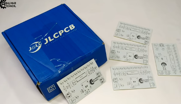
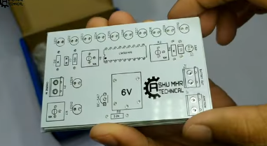
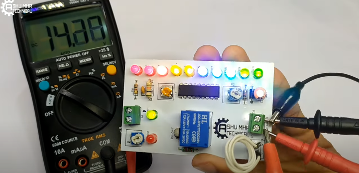
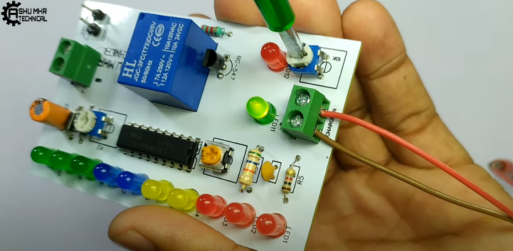
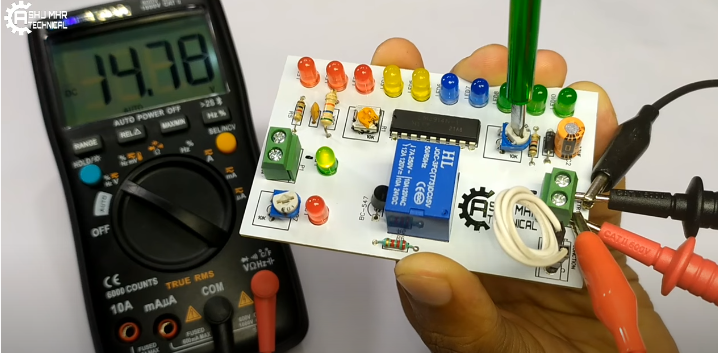
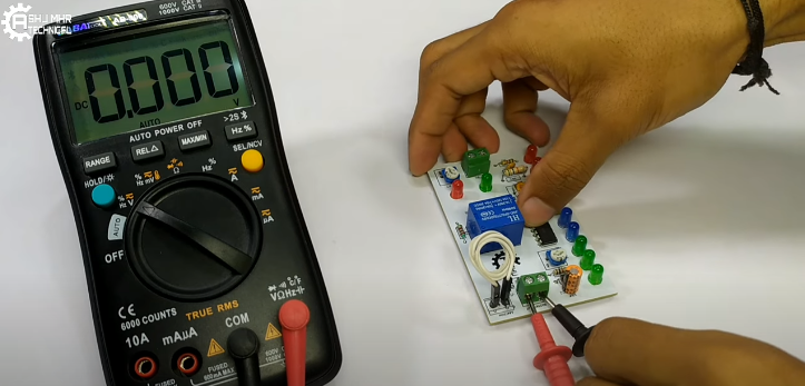
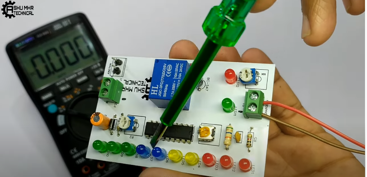
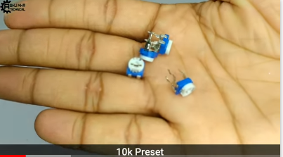
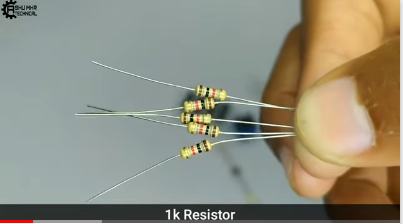
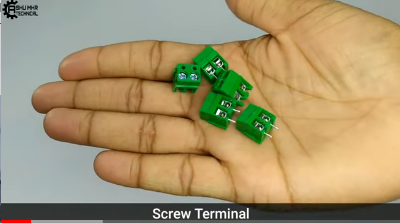
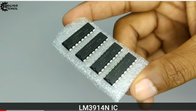
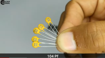
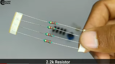
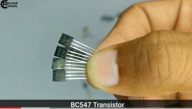
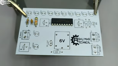
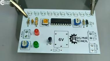
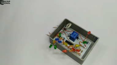
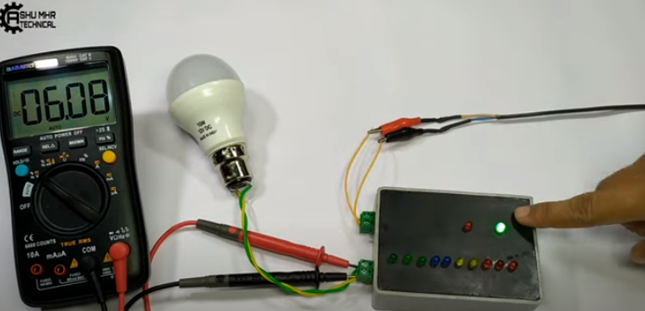
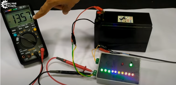
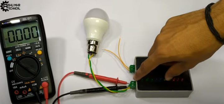
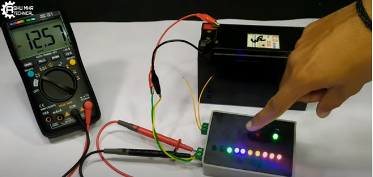
Battery Charge Controller
This is a very advantageous yet easy to make project. It prevents the battery from overcharging. We call it "Battery Charge Controller".
 ASHUMHRPROJECTS
Become a Hackaday.io member
Already have an account? Log in.
Just one more thing
To make the experience fit your profile, pick a username and tell us what interests you.
Pick an awesome username
hackaday.io/
Your profile's URL: hackaday.io/username. Max 25 alphanumeric characters.
Pick a few interests
Projects that share your interests
People that share your interests


 Rory
Rory
 Electroniclovers123
 Essentially Space