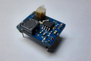
This Power module design is based on the TI LMZM33603, which can take voltage input of 36v, and step down the output based on resistors chosen. I opted to step down to 5v to power my Pixhawk servo rail, which I've connected to a small servo turret. I plan to eventually place a rangefinder on the turret to create a scanning rangefinder. I used ChipQuik lead free NC191SNL50 as a suitable solder paste.
3x2 panels arrived from PCBWay and I went to work trying to find the optimal profile to solder the tricky QFN package. Using a T962, I played with the reflow profiles and had to create a new profile. After a lot of trial and error, I was able to get a working prototype, however I realize my solder stencil could use some work after seeing solder beads form on the qfn package on some of the boards came out of the oven.
The board prototype v0 seemed to work well enough, though powering a servo turret is probably small potatoes considering the current carrying capacity of 3A. Design considerations for V1.0: 0802 and 1206 passives, a better solder stencil layer, more I/O, pixhawk jst-gh connector, terminal block for input voltage, and of course marking the input and output voltage on the silkscreen layer. It's a good thing I have until 2024+ to refine my design, as modules are out of stock everywhere and are lead time 100+ weeks.
See YouTube video for the rest of the project progress.
 Muhammed Esad Işık
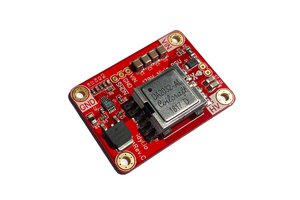
 Tony
Tony
 c.Invent
 Rue Mohr