 Hunter Santana
The Airman Rocket
Technical Paper
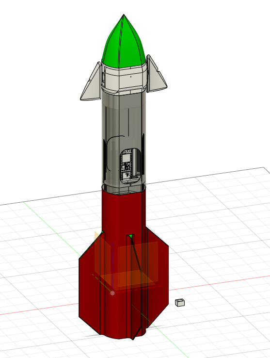
Table of contents
- Title Page
- Table of contents
- Abstract
- Problem statement & Rationale
- Design
- Design cont.
- Design cont.
- Evaluation
- Evaluation Cont.
- Conclusion
- Conclusion cont.
- references
Abstract
Model rocketry is an advancing hobby, those who participate in rocketry are always seeking ways to push the technical boundaries of the hobby. Creating a system that can perform well, can be tuned, and get recovered are goals of any hobbyist. Embedding computers in rockets is increasing the sophistication of rocket systems, it can allow the user to record data and perform flight maneuvers such as stabilization, stage separation, or guided flight. Legacy systems feature separate computers each for handling different tasks such as booster ignition, parachute deployment, or stabilization. Newer systems such as the EasyMega by Apogee Components or the Signal R2 TVC Kit from BPS space can perform these tasks simultaneously but at a high price tag of $350. Airframes for model rockets are traditionally made of cardboard or carbon fiber, but these materials make it difficult for custom shapes or added airframe complexity.
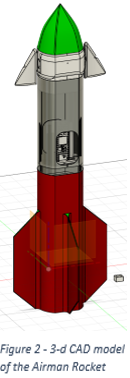
The Airman Rocket is a fully 3d-printed, auto-stabilizing, and data collecting model rocket, the rocket is designed to be fully re-usable, modular, and open source. It features an on-board flight computer, accelerometer, and servo driver for performing data collection and rotation stabilization. Stabilization is achieved through small wings on the front of the aircraft that are actuated by servos for steering.
The entire build of the Airman rocket can cost as little as $80 and offers a higher degree of customization than the other systems. In addition to the flight computer the actual rocket and flight components are included in this price tag. All documentation and files for the aircraft are available for free and is built by the consumer. The Airman rocket keeps the cost of entering the hobby low and acts as an educational tool and community platform for Those who chose to participate in the project. The rocket a still maintains high performance as a priority and accomplishes the flight profile for which it is designed.
Problem statement
Using a model rocket as the instrumentation platform, how can I record data, stabilize flight, and recover the rocket using only open-source hardware and software? The solution must be free as an intellectual property and be more affordable for the user than current options on the consumer market. The solution should allow the user to expand on the original project and learn various aspects of model rocketry.
Rationale
Using open-source micro-controllers for the rockets primary flight computer has large advantages such as; the ability for I/O expansion, the ability to be programmed in modern powerful code languages, and highspeed processing. Stabilization can be most easily achieved through fin-control in high speed applications. Fin-control was chosen over other control methods such as thrust vector or reaction wheel control because of its low mechanical complexity. 3-d printing achieved low cost custom parts. Parts could be quickly and easily prototyped and tested. Attempting to make the complex parts involved for an aircraft of this type would prove extremely difficult using any other method. 3d printing allowed for a very unique airframe shape that would be almost impossible to make using traditional methods. Posting the files online for free allows the project to build a larger community and allows the technology to disseminate to as many people as possible.
Design
For the airframe of the rocket the design was done in a CAD modeling software. The models were then exported for 3d-printing and were fabricated in PETG filament. PETG was chosen over PLA for its slightly lower weight and higher melting temperature, this would allow the rocket to fly higher and give parts better resistance to the heat generated from the rocket motor. Unlike most rockets the fuelsalage has two flat faces connected by semi-cylindrical faces. This gives the rocket a slightly smaller foot print than a full cylinder and also allows parts to fit together perfectly with no alignment necessary.
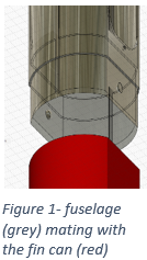
For parachute deployment the main fuelsalage and fincan are separated by a blackpowder charge built into the propulsion device. (see figure 1) when the powder is ignited the expanding pressure in the fincan causes the mated parts to un-couple. (See figure 2)
The separated aircraft parts remain tethered using parachute chord and the parachute itself is attached to the tether and is freed upon separation.
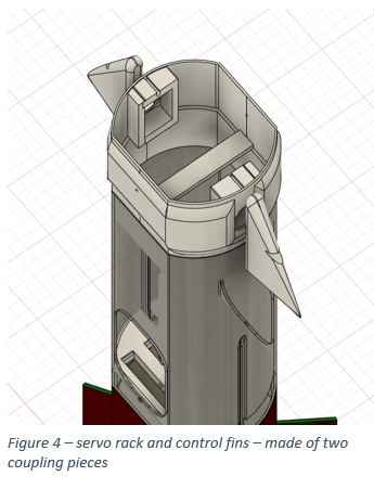
The fin control system uses two metallic geared MG90 servos, plastic geared sg90 servos were found to have weak gears and stripped easily. Servos are mounted in both sides of the aircraft and wings are then screwed into the servo gear shaft through the center of the wing. (See figure 4)
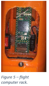
The flight computer is a teensy 4.1 micro controller. The controller was chosen because of its plethora of open source libraries, 600Mhz processor, and built in SD card reader. Powering the electrical system is a 9v 600 mAh battery. The 9v is transformed to 5v using a buck converter and this power is sent to a bus bar for 5v power distribution in the aircraft. The 5v bus powers the micro controller and servo controller. All other busses are controlled and powered by the microcontroller. This includes; a 3.3v bus, a ground bus, clock signal bus, and a data bus. On these busses additional I2C and hardware devices can be added to the system for additional capability.
The sensor on board is a MPU 6050, this sensor is used to derive an angular measurement. This angular measurement is then fed into a PID algorithm during the control loop of the code. This PID algorithm generates a real-time output, that is then multiplied by a gain coefficient. This final result is an angular deflection that is written as a servo output that actuates the servo and turns the wings. The goal of the algorithm is to take the current angular measurement and bring it closer to the set point of 0 degrees by causing the control fins to turn making wind deflect and turning the aircraft.
This control loop runs at approximately 20hz with no overclocking or optimization. This allows the aircraft to make quick adjustments during flight and collect data with high resolution. Every time the control loop cycles, measurements for current angle on all three arises is recorded along with the timestamp and current servo angle. These values are separated by commas and written to the onboard SD card. This makes for easy exporting to Microsoft Excel for data analysis.
Evaluation
The design proved functional in almost every task expected of it at least once throughout the duration of testing. The airframe proved to be functional and mostly in tact upon successful recovery and even crashes. The only issues with the airframe were caused by the high temperatures of the black powder. Excessive warping from the heat generated during separation would often render the fin can portion of the aircraft unsalvageable. This was fixed in the second test by employing aluminum heat shielding, When applied uniformly the aluminum tape not only deflects heat but also helps to maintain the airframe shape when exposed to it.
For recording of the tests, 3 cameras were set up at different angles for video recording. The rocket would be placed on the launch pad using the launch lugs, wind speed would be acquired and trajectory of the rocket would be aimed to go against the wind for closer recovery. The rocket is now powered on and calibrated, the operator can now insert the igniter and move 30 feet away for the countdown and ignition.
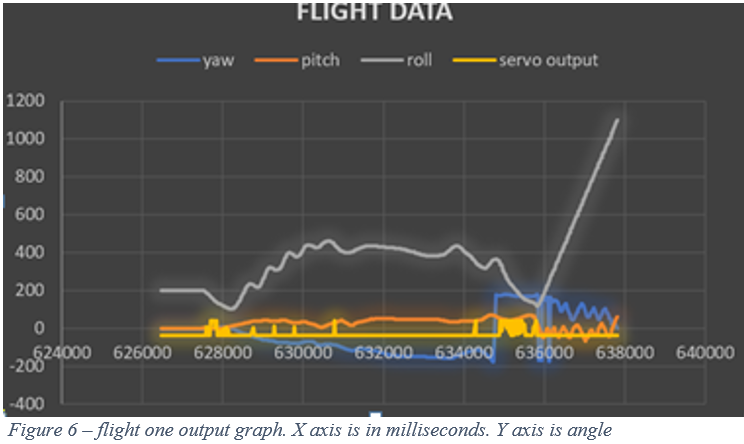
The control fins proved to be sufficient in changing angular velocity but the system had failures in other aspects of the test(refer to figure 6). Observing the chart, it can be seen that the ‘servo output’ line has a clear relationship with the ‘roll’ line. Every time the servo output line shows a positive spike, the roll line begins to go negative. However even though the system was making corrections, the system was never able to correct to the desired setpoint. This was because a zero-drift error had accumulated over 600 seconds while the rocket remained on the launch pad. Essentially the accelerometer was outputting an incorrect angle of 200 degrees, this was caused by a poor calibration. Because of the outstanding error over 600 seconds an issue known as integral windup occurred making it difficult to return to our setpoint. A process saturation was experienced where the physical output is constrained and the integral error keeps accumulating. It was determined that allowing more time to calibrate the accelerometer would result in less zero drift preventing the integral error to accumulate.
Figure 6 – flight one output graph. X axis is in milliseconds. Y axis is angle
video analysis of the second flight appeared to show increased stability in flight. This increased stability in flight was partly due the new calibration process. However data could not be recovered from the test due to a parachute failure. The parachute failure came from user negligence.
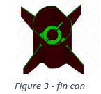
The legacy design of the fin can featured holes in the bottom for a launch rod but these holes were being filled with glue usually to allow increased pressurization of the fin can for enhanced separation, however use of glue was redacted from this flight and because of this, small holes in the fin can relieved too much pressure and separation did not occur.
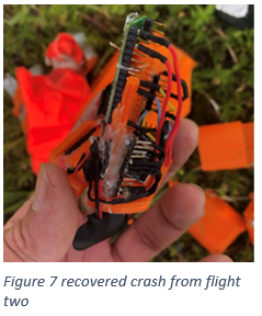
In the rocket crash the data had corrupted upon hitting the ground however the flight computer rack had remained mostly in tact with the micro controller continuing to function on recovery.
Both flights had achieved an altitude of 100-400 feet based on anecdotal estimates and video analysis.
Conclusion
The design shows clear promise as a cheap educational kit for PID control and model rocketry. The design is simple yet effective compared to other solutions such as the BPS space Signal R2 Kit at a significantly lower cost while also retaining similar specifications such as the same processor but improving on other aspects like having a smaller form factor and lower weight. The test results show that the fins do actually work as a control surface and that the algorithm, while not bulletproof can provide optimal flight correction and recording in ideal conditions.
More testing would have benefitted the project as small changes still need to be made. Increased heat testing would be ideal to see how to best print and protect the airframe parts from heat damage. More evidence of the fins and algorithm working as intended is needed, producing good analytics will allow for detailed report on how the aircraft flies.
This project would not have been possible without the use of 3-d printing and rapid prototyping, hundreds of hours of printing allowed the design to remain flexible and accomplish dynamic and changing goals. The code has also proven to be robust since the latest rework, zero – drift error is now solved. If recovered properly in a new flight the current configuration would perform better than legacy flights.
The project has now been taken public on the website Hackaday.com, this will allow others from around the world access to the files and materials to join in on the community project. The goal to allow others to build and expand on the project, thus collecting more data for the platform will allow for more detailed analysis in the future. Open-source technologies allow people of all backgrounds to participate in the hardware and software revolution, providing users with all associated files for constructing the rocket will improve the product and allow the most possible participants to join.
References
- https://hackaday.io/project/185204-the-airman-rocket
- https://bps.space/products/signal-r2
- https://www.pjrc.com/store/teensy41.html
https://www.apogeerockets.com/Electronics-Payloads/Dual-Deployment/EasyMega