Close
0%
0%

Multispectral imaging smartphone camera

A smartphone imaging system for art conservation analysis

Public Chat
Similar projects worth following
This project entails modifying a smartphone by removing the IR/UV filter and designing a filter wheel for various types of imaging: IR reflectography & fluorescence, UV reflectography & fluorescence, and polarized light, as well as a full set of multispectral bandpass filters. These methods are frequently used for analysis of artworks and artifacts, however, they currently require lengthy setup times, dedicated studio space, and maintaining a whole kit of DSLR filters. This smartphone system enables most types of technical photography to be done in seconds, and can be easily paired with photography software through apps and APIs to increase its capabilities.
Future additions to this system will include replaceable wheels for macro lenses of varying magnifications, removable light modules with IR/UV/White LEDs, and potentially other removeable modules for sensors/analytical tools such as a spectrometer.

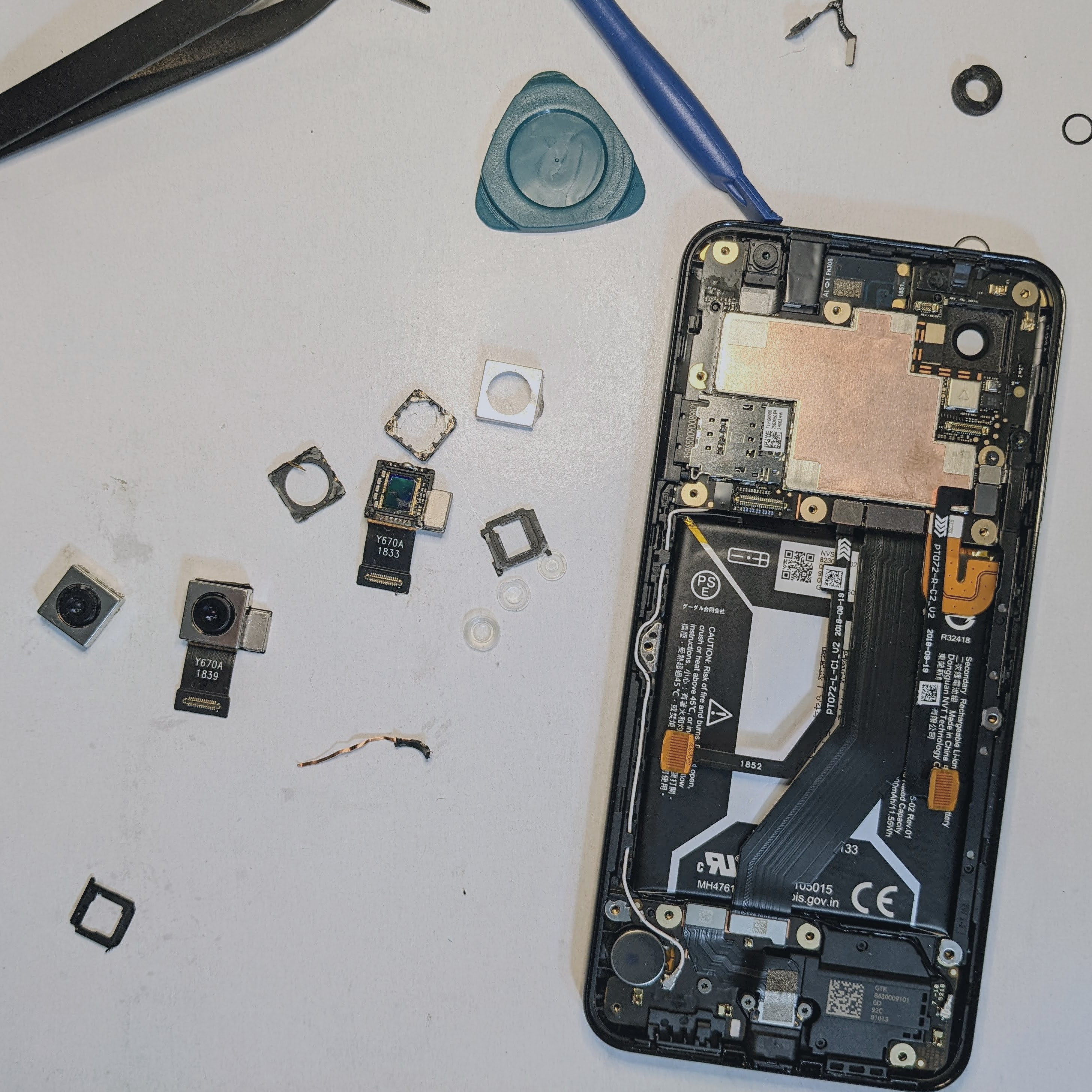
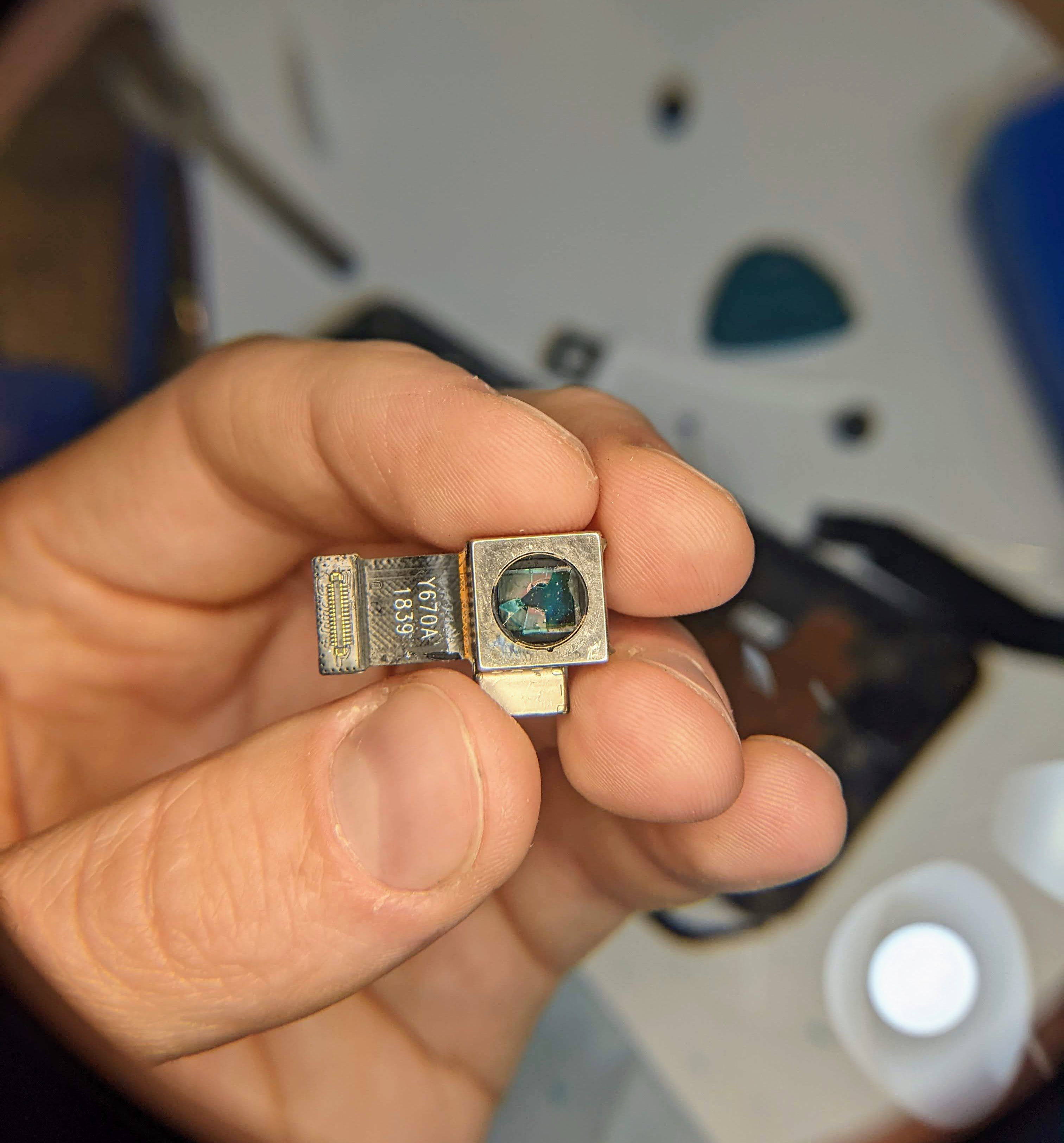
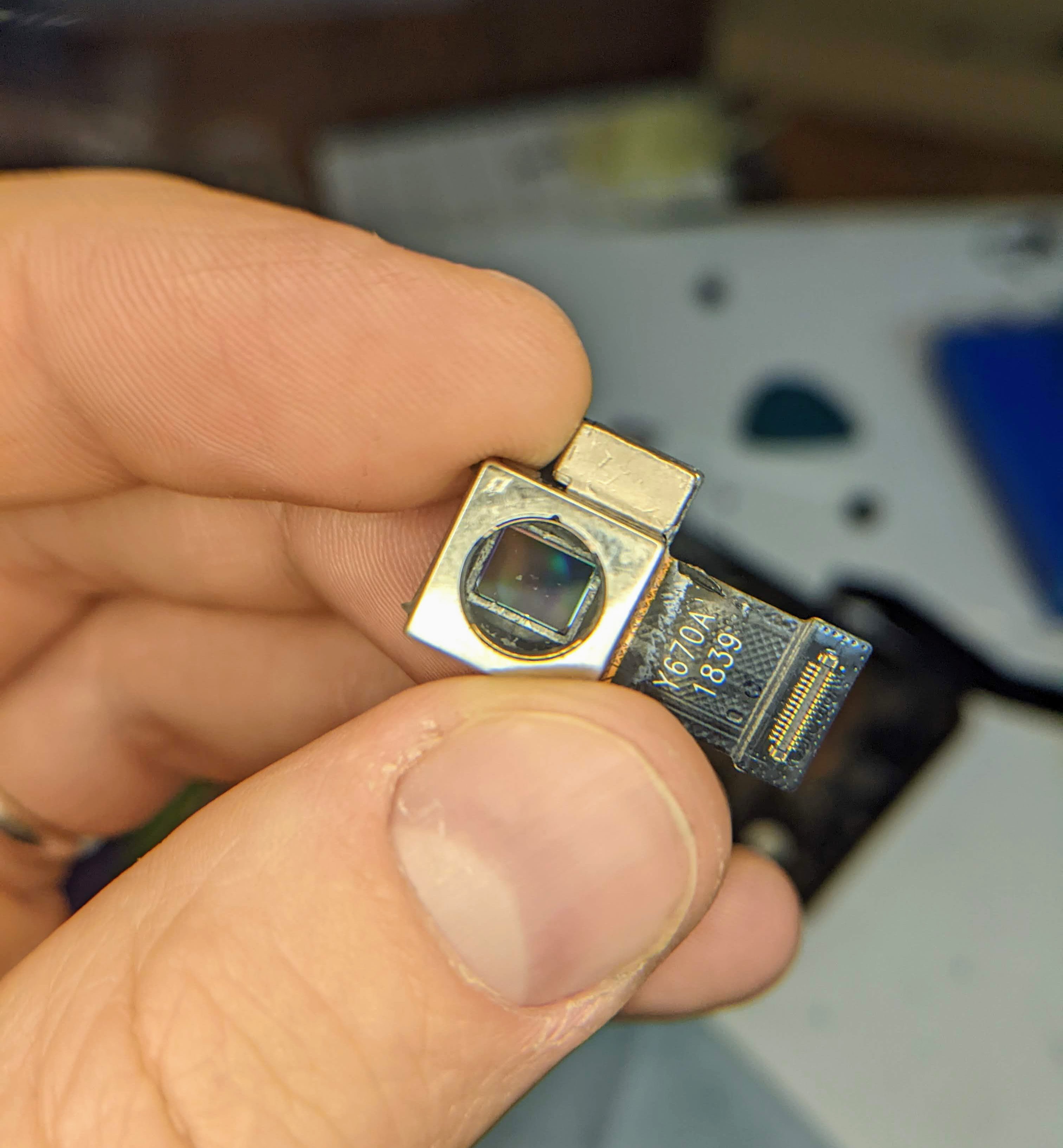
This project started with utilizing a separate USB camera module, removing the IR filter, and interfacing with a smartphone with an app. That turned out to be a lot easier than modifying a smartphone, but was limited to the lower-quality cameras and USB camera software. I've gone through about a couple dozen smartphone camera modules to find ones that were able to be modified and the method by which to do so.

Finally, it's starting to work.

I've been using the Google Pixel 3a because it has great camera software, excellent night and astrophotography modes, and used versions are available very affordably. 

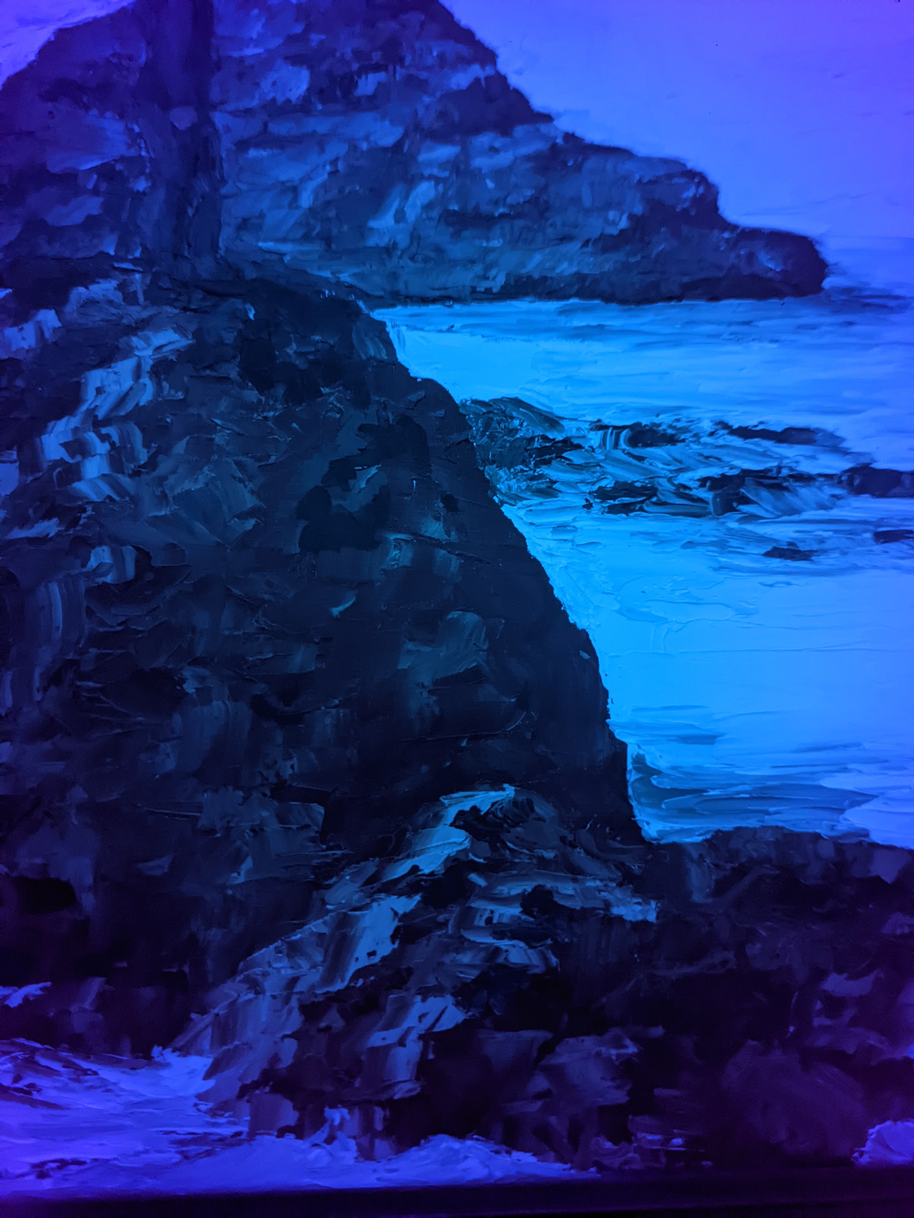
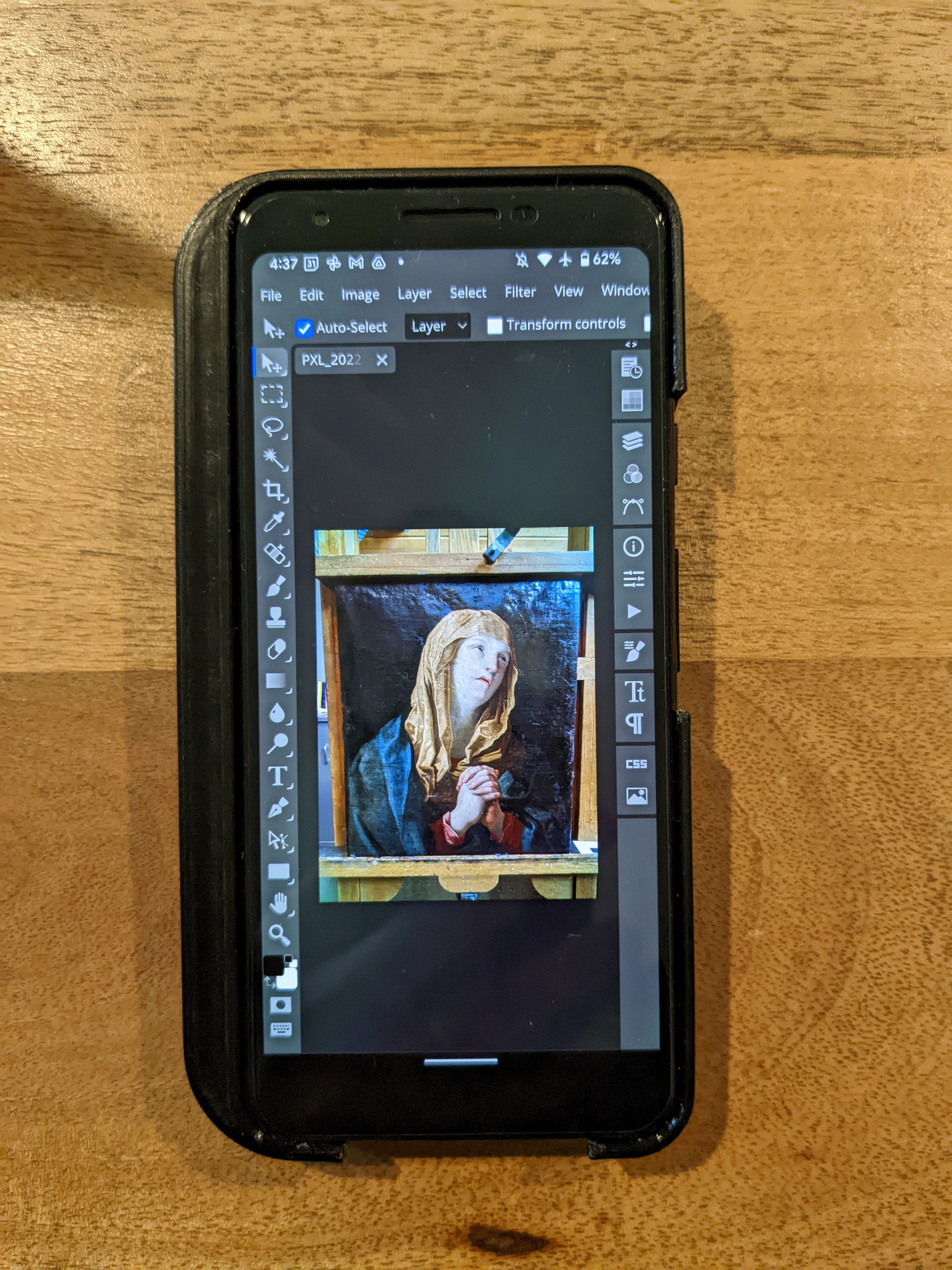
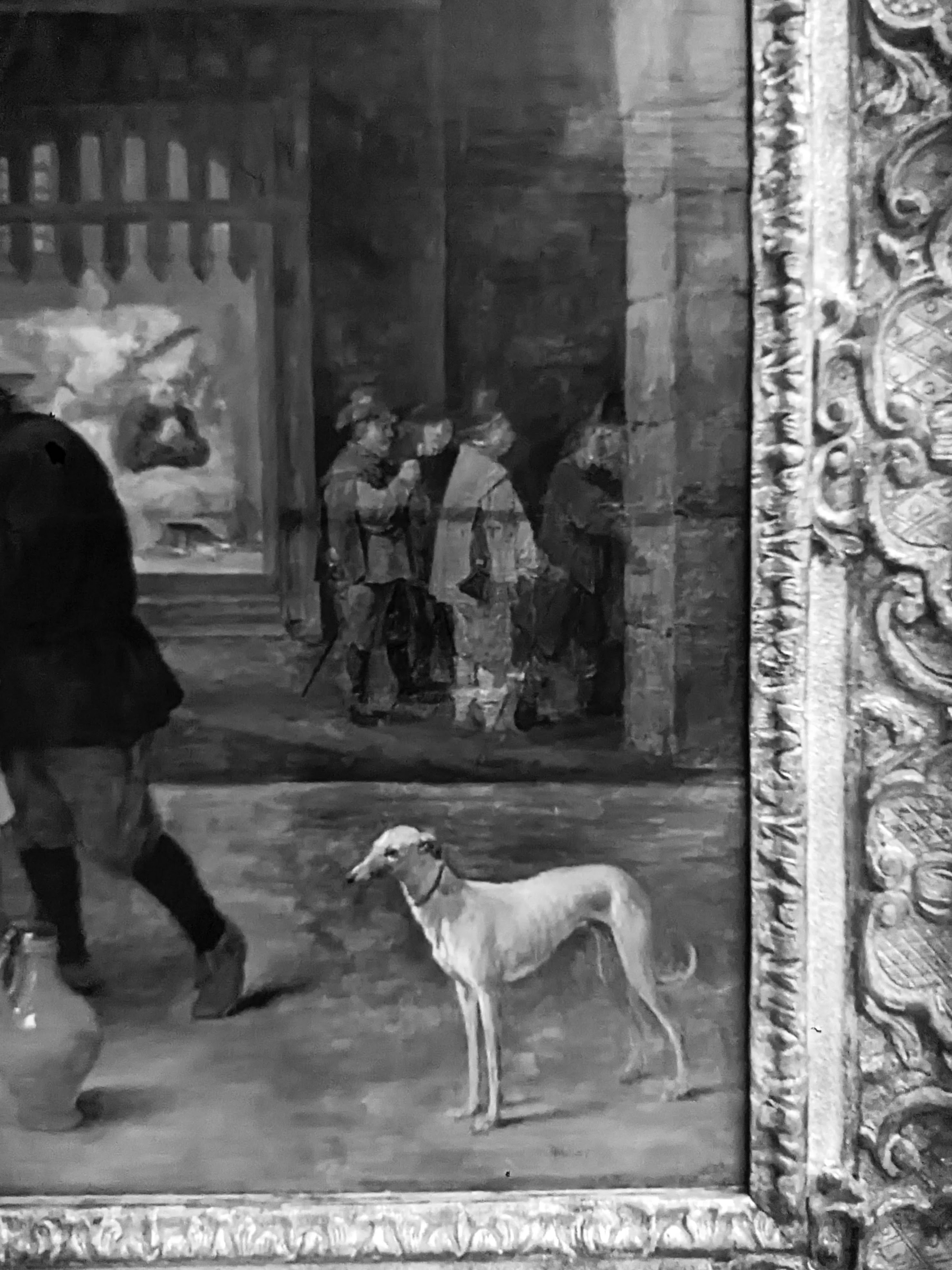
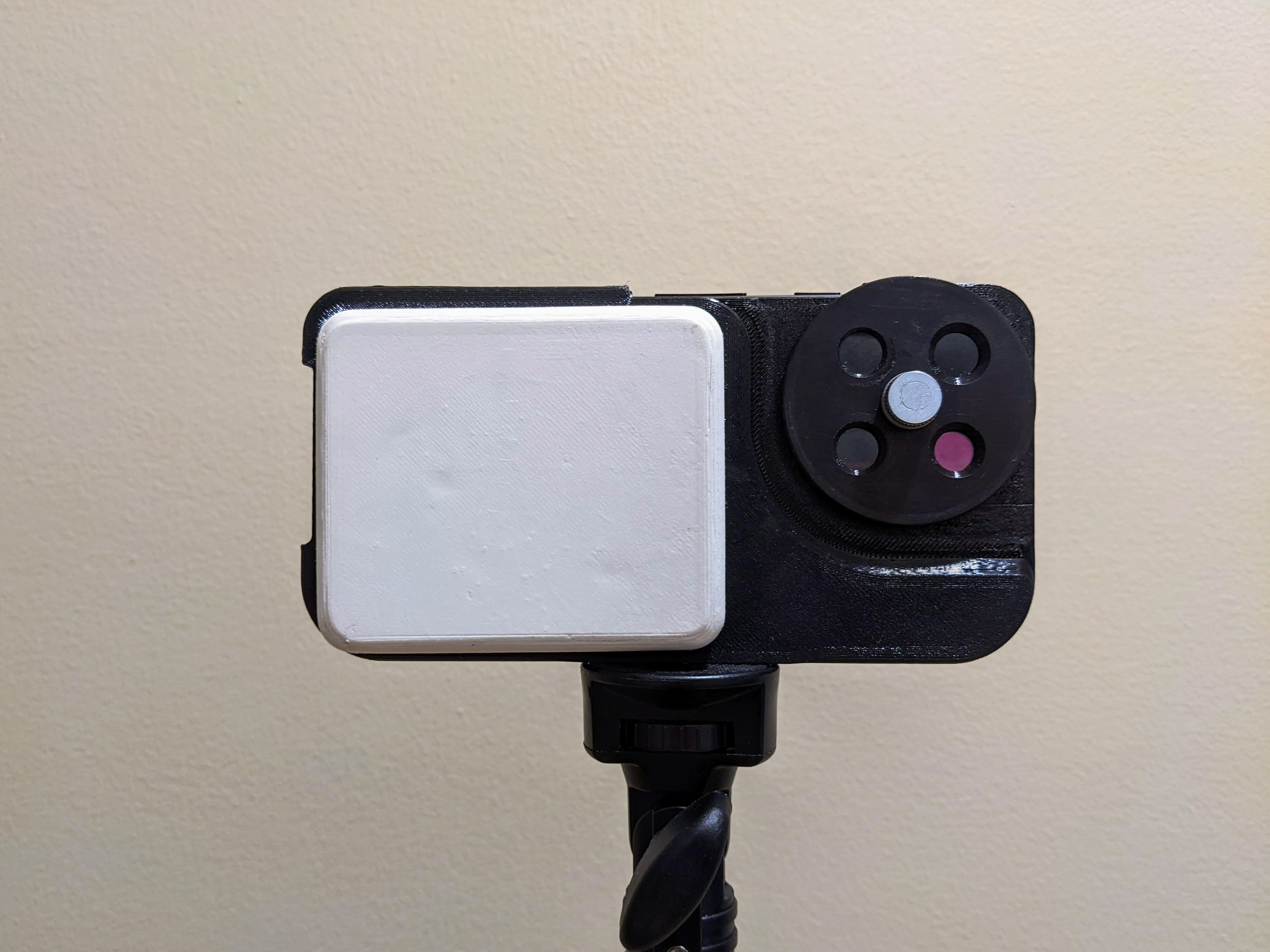
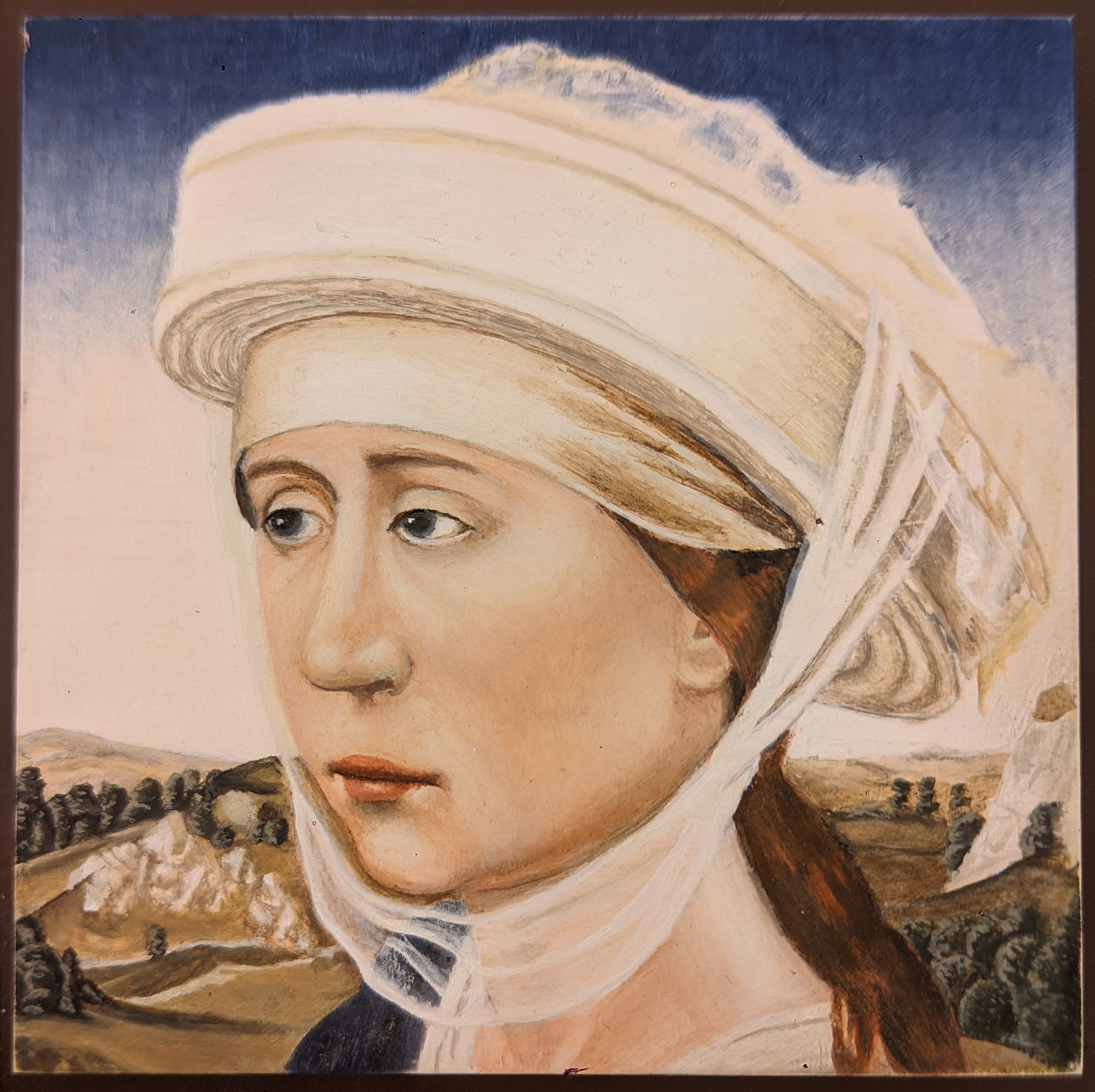
Here's the first working version in action on an oil painting:

What we're seeing here is

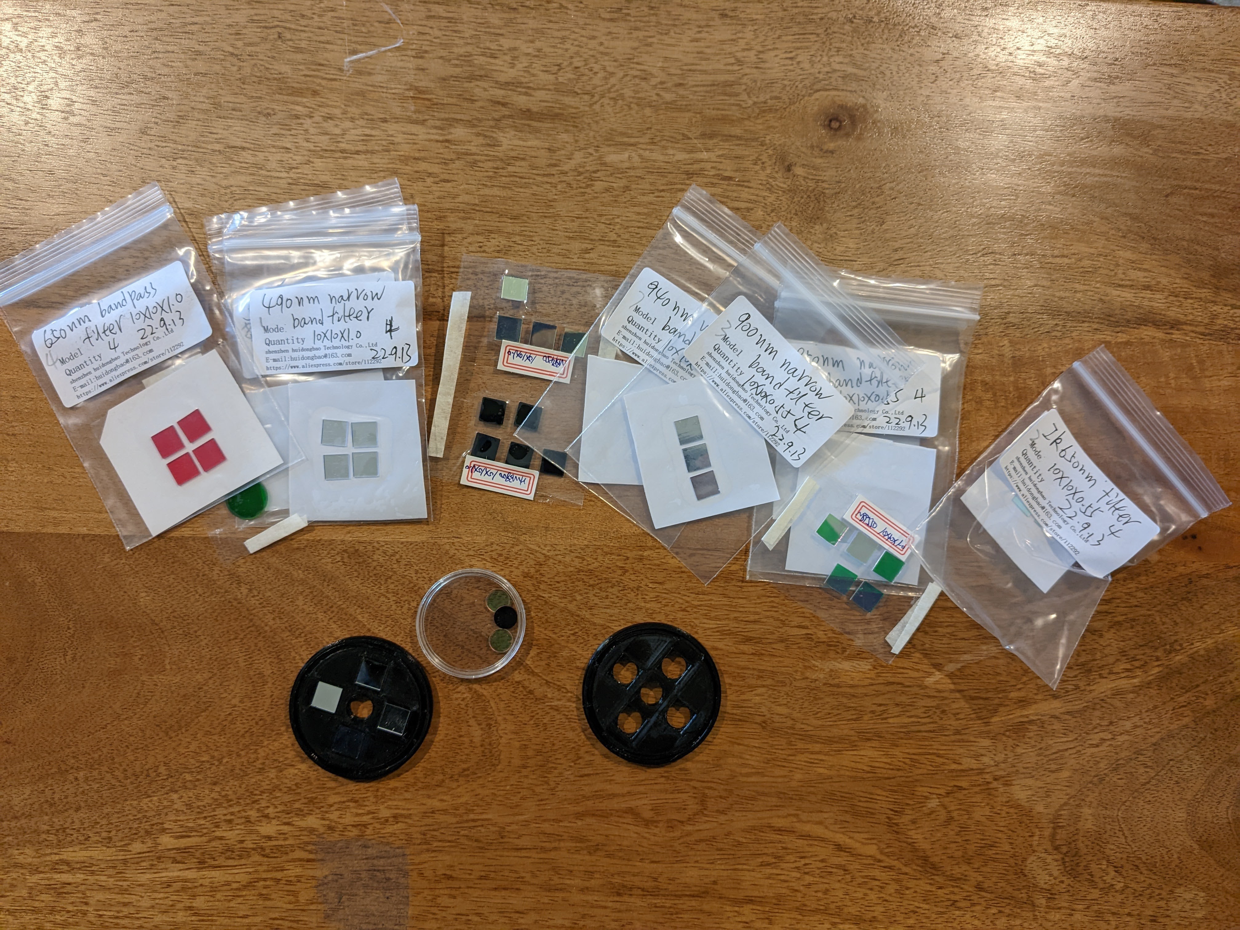
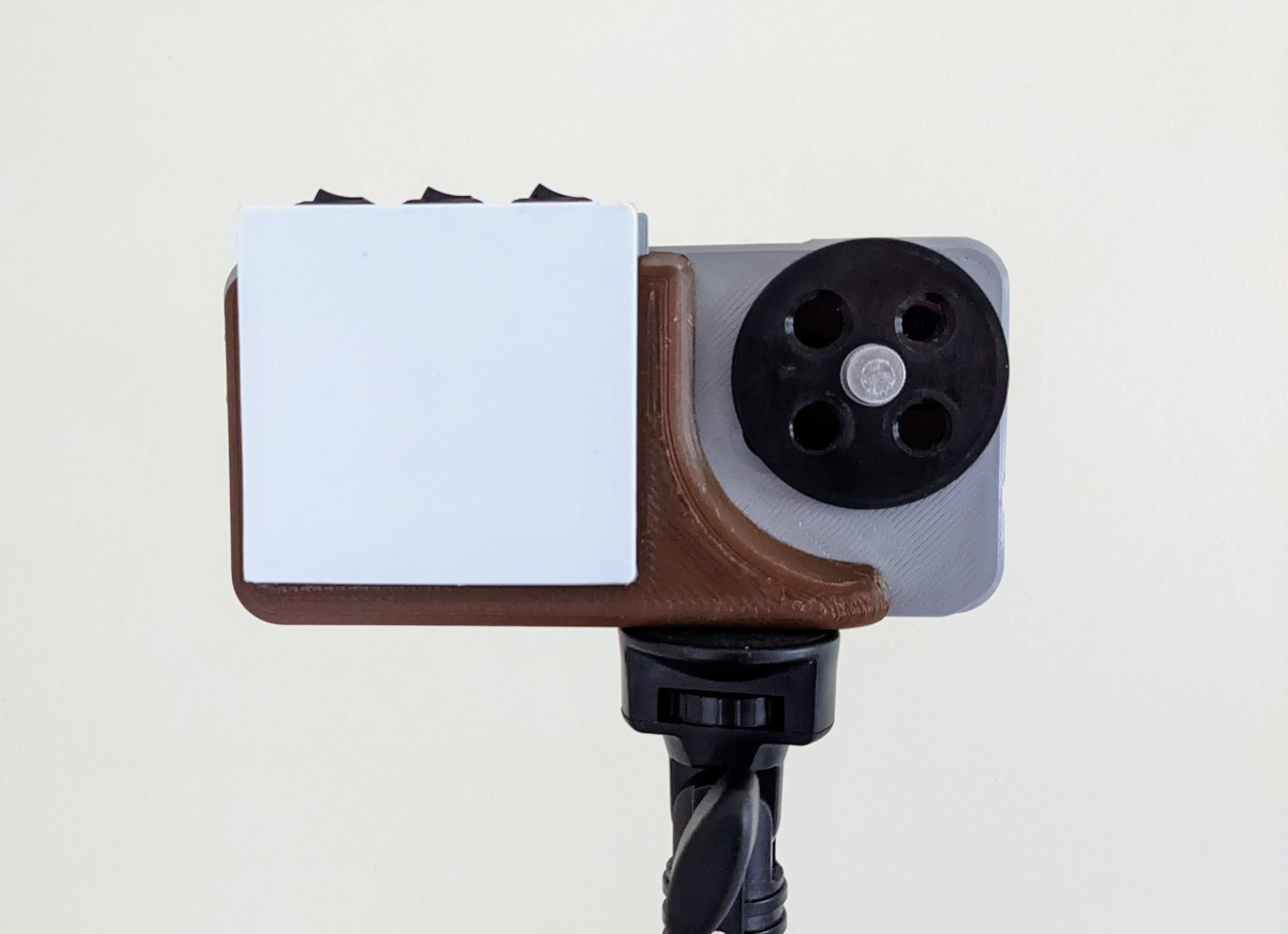
1) Infrared long pass filter--this filter doesn't allow light below approximately 760nm through. Often, this is used in art conservation for IR reflectography to see drawings on the canvas below the paint. Certain paints/pigments that are opaque in visible light are transparent in IR.

2) UV short pass filter--this is typically used in art conservation to differentiate certain paints: lead white (which has been used for centuries) shows up as white in UV reflectography. Titanium white (which was developed much later) shows up as grey. A handy way to determine if paints are historical or not.

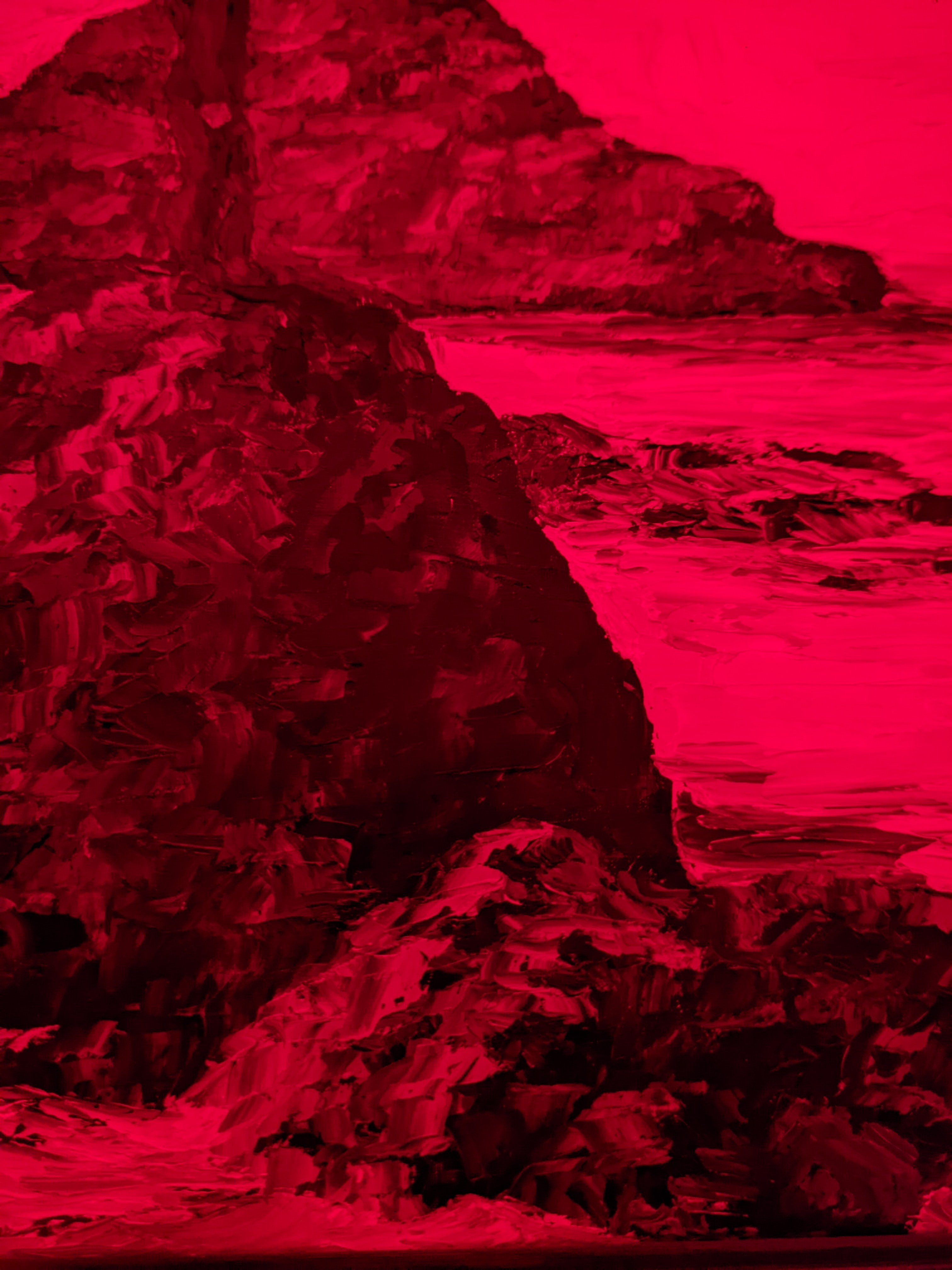
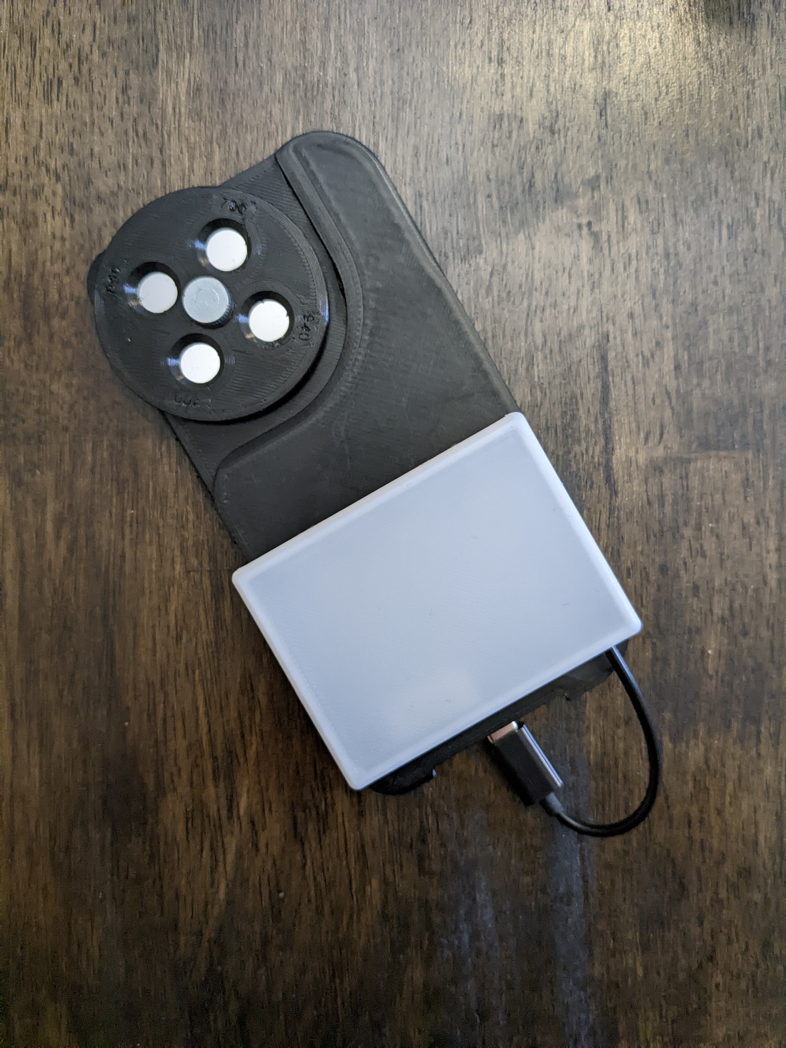
3) Polarized--often used for reflective objects or if a painting has a high gloss varnish over it. Makes it easier to see true colors and some previous restoration. In the current version, I need to cement a visible light pass filter to the polarized lens, otherwise, it lets in everything from UV to visible to IR.

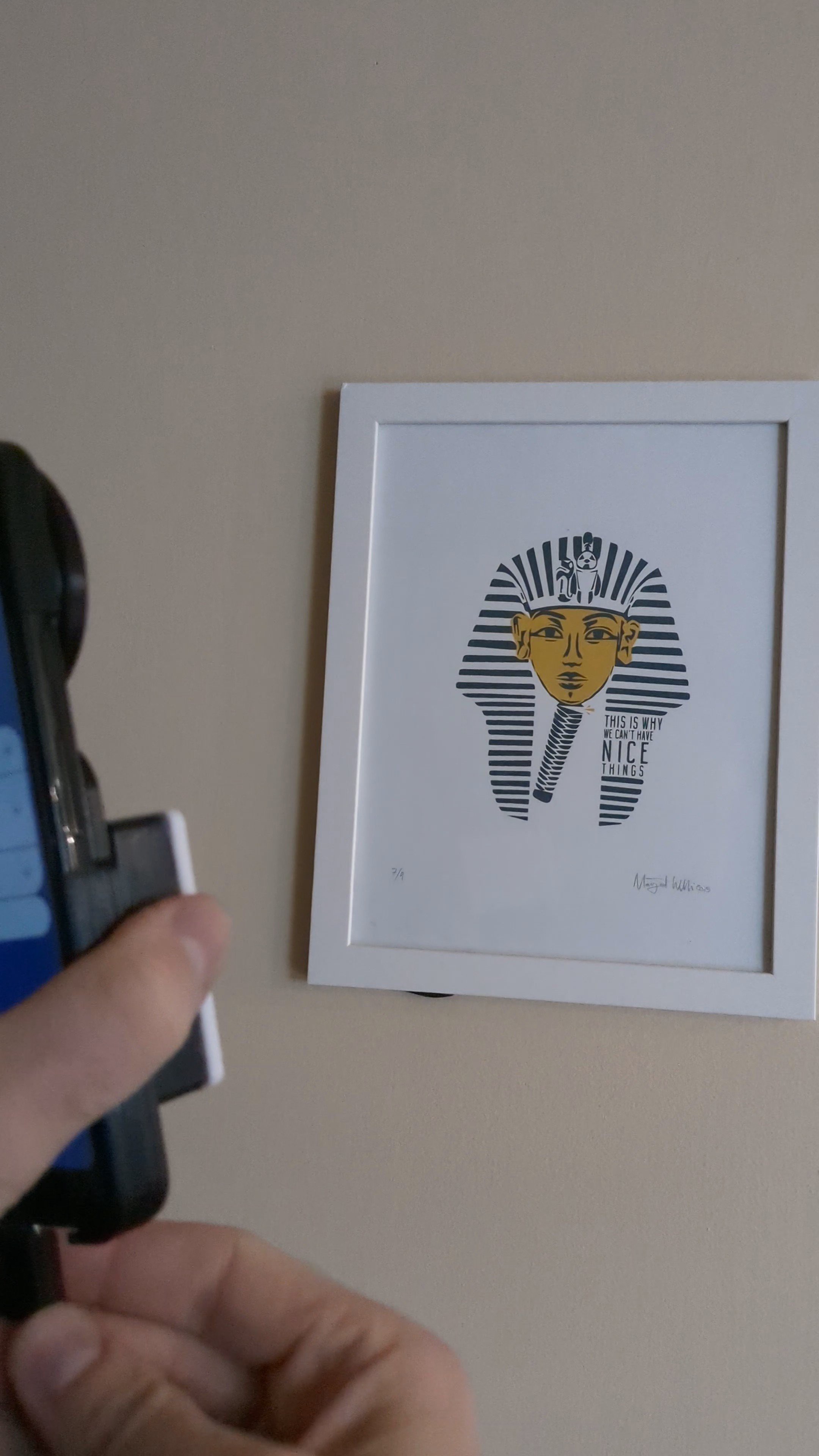
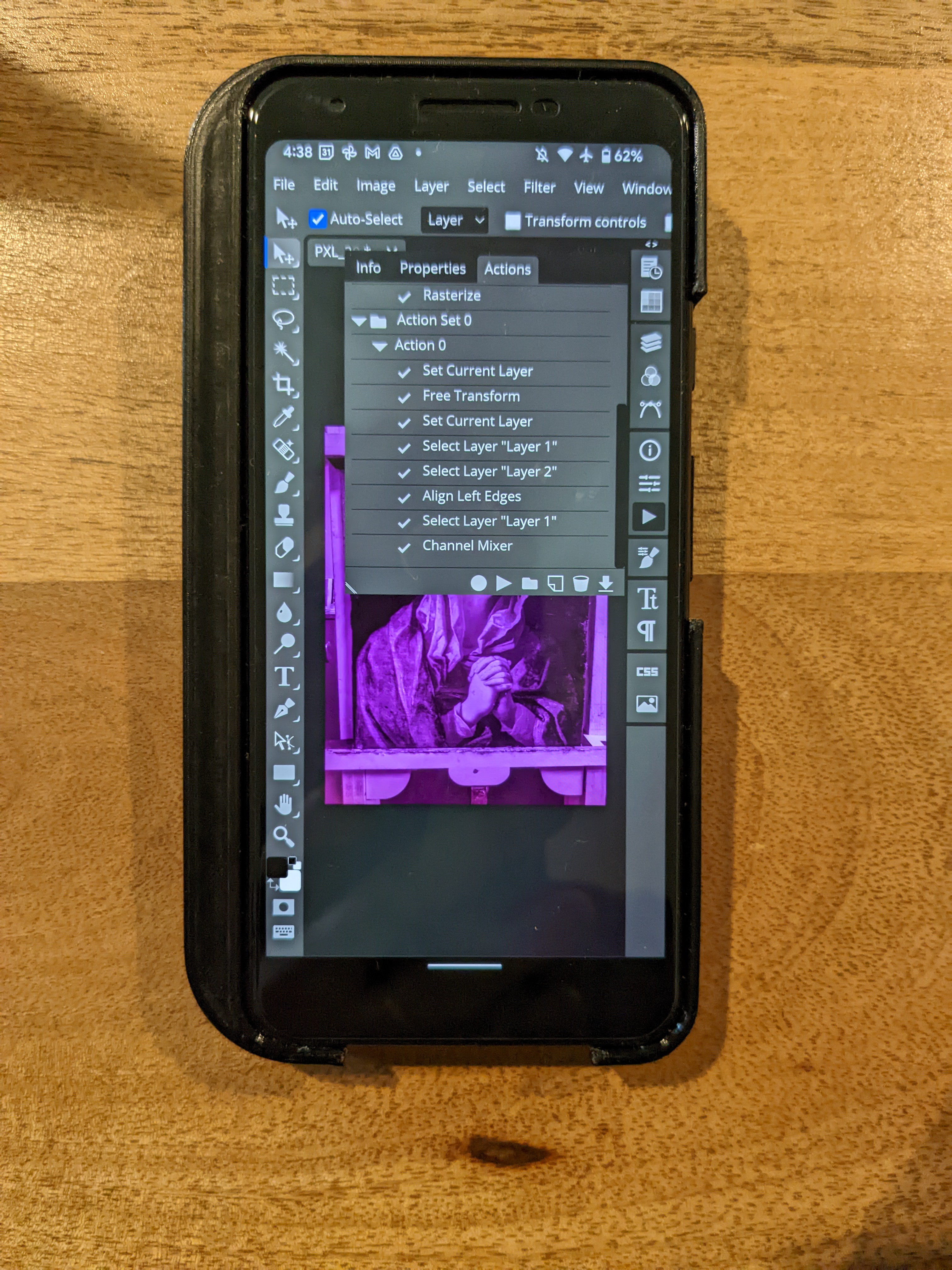
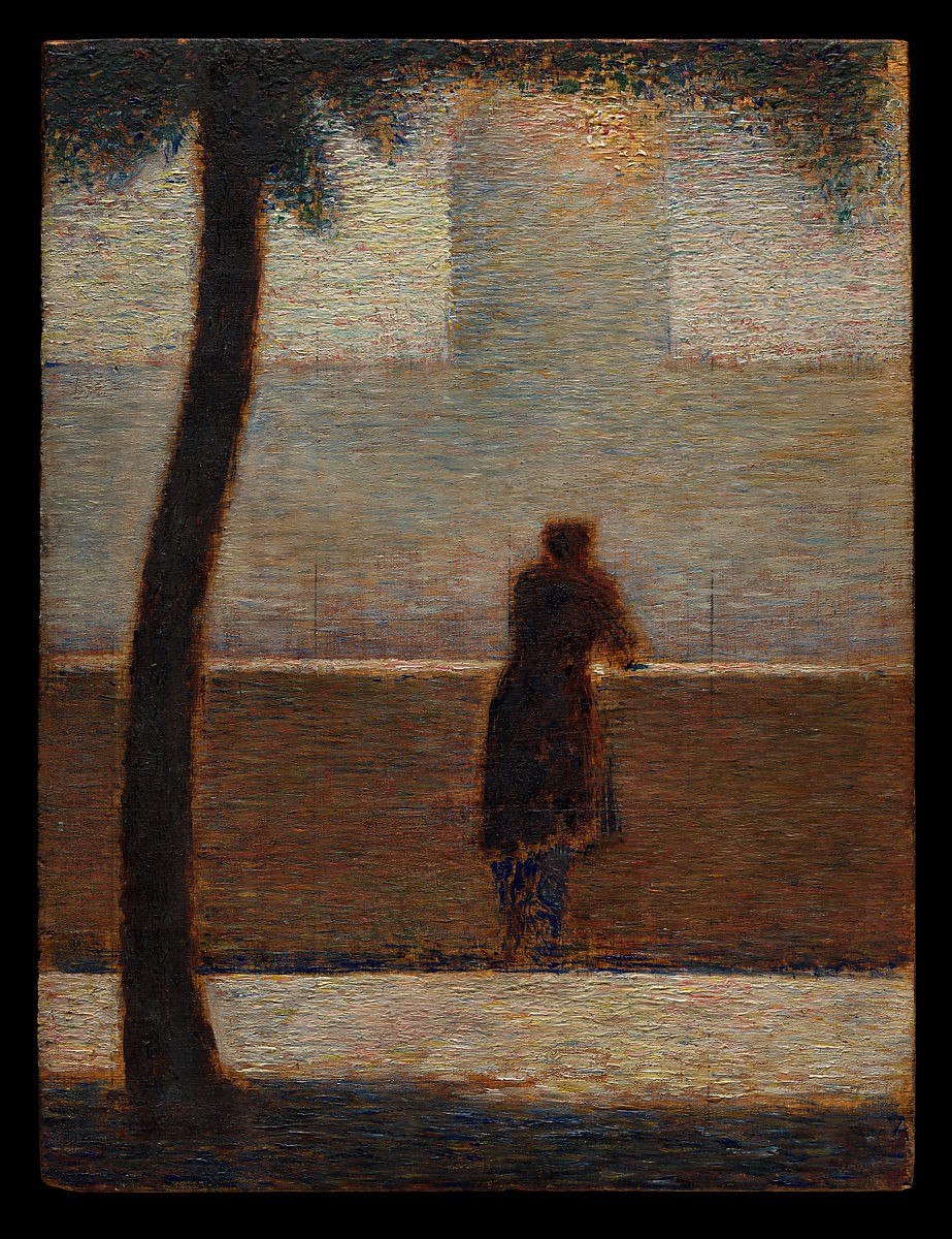
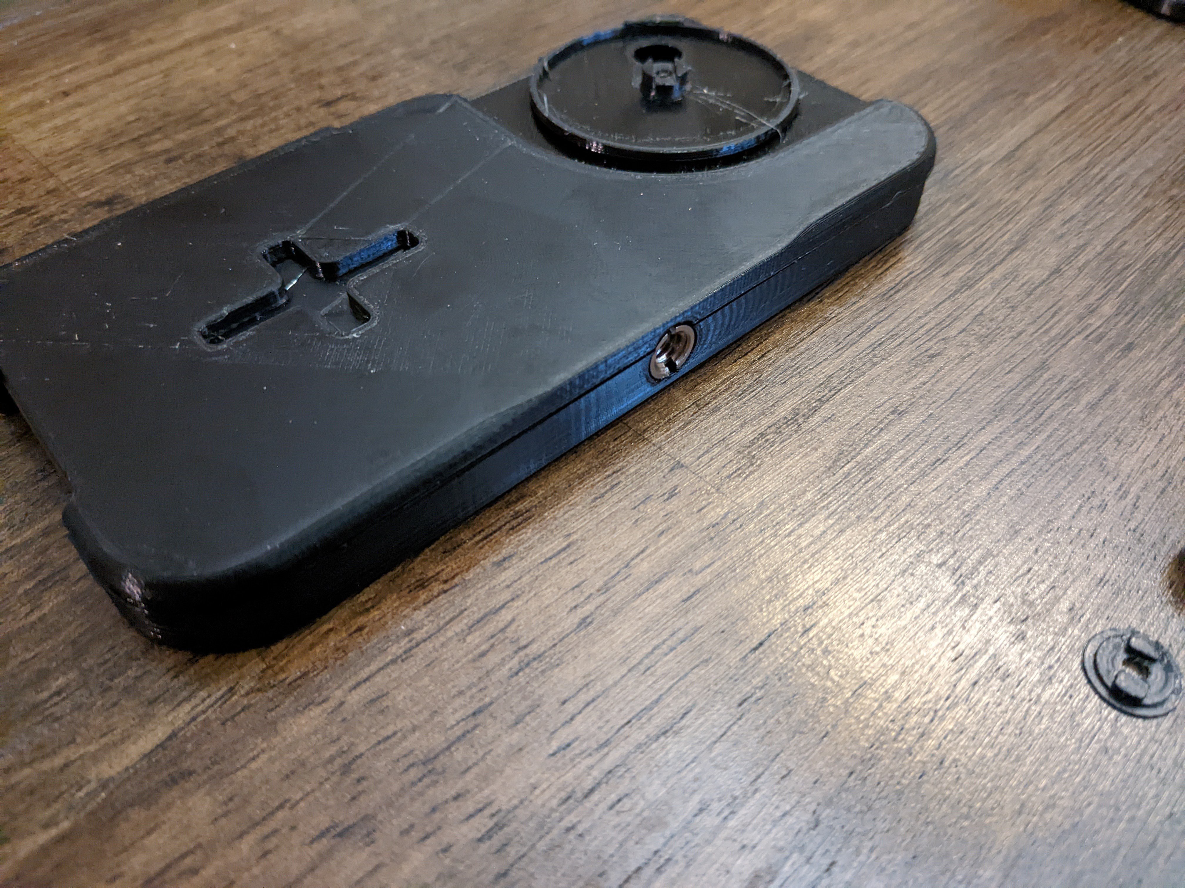
Update 6/28/2022: Using the camera and case w/ tripod mount to snap coinciding visible light and IR photos, which reveals the underdrawing (the pencil sketch on the canvas under the paint).

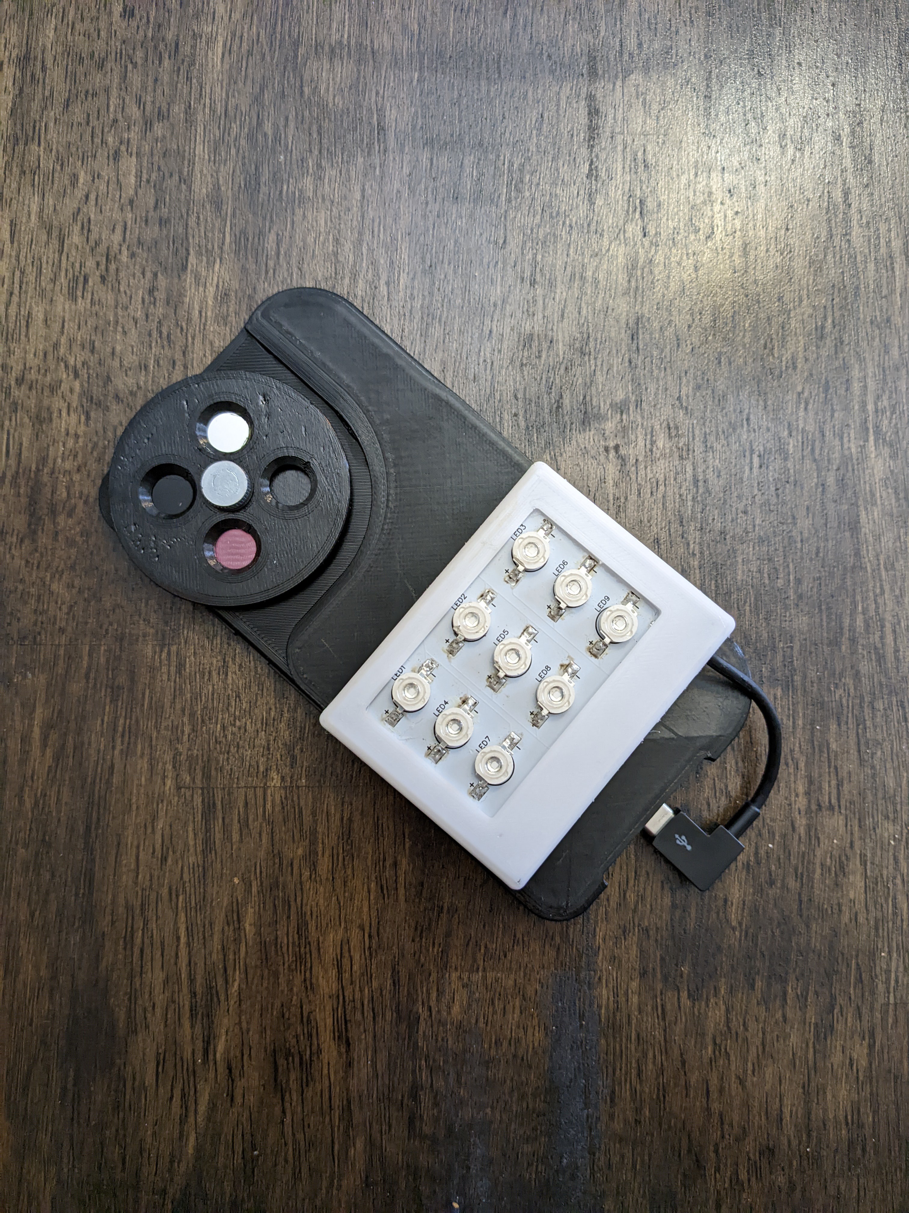
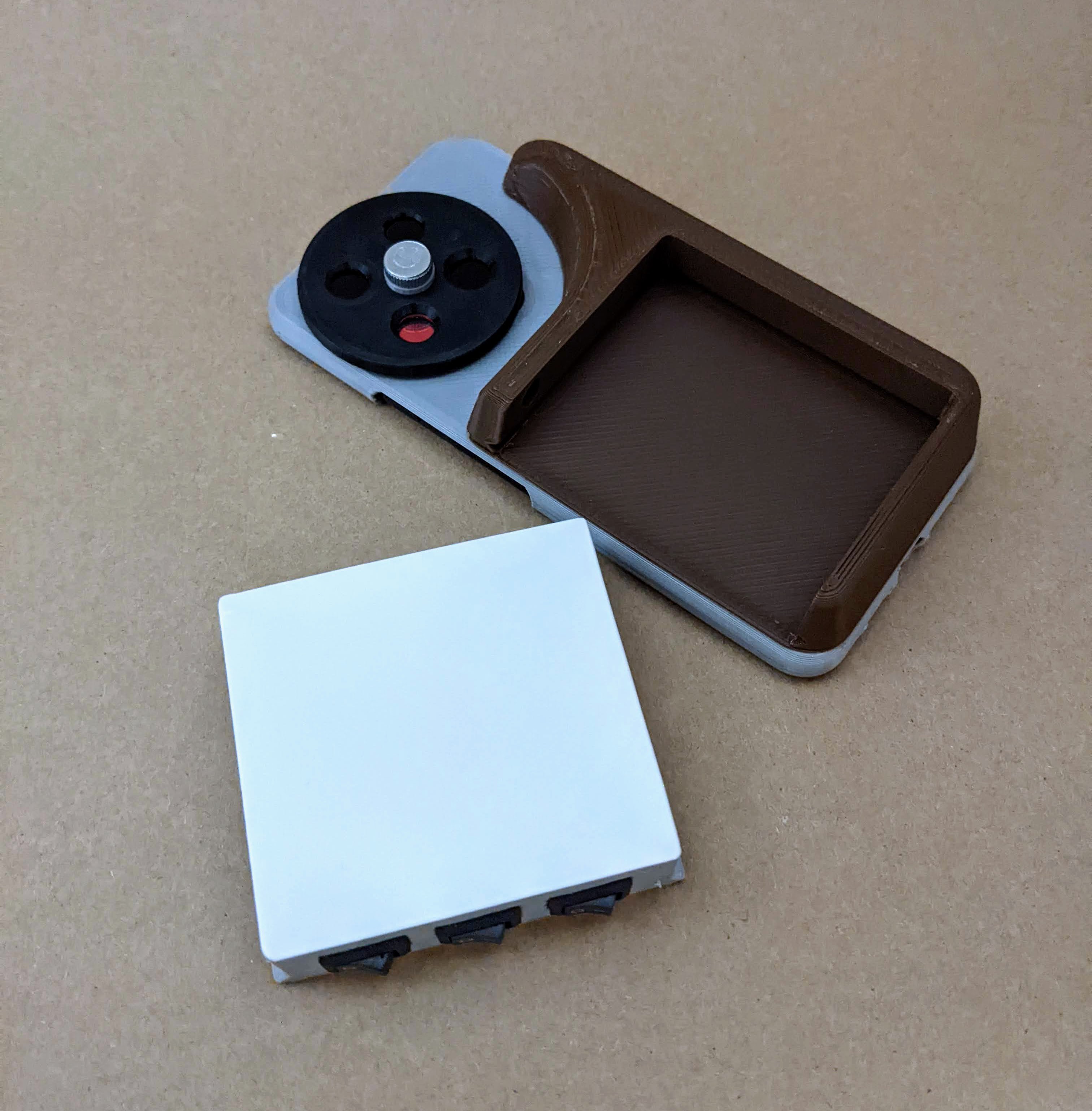
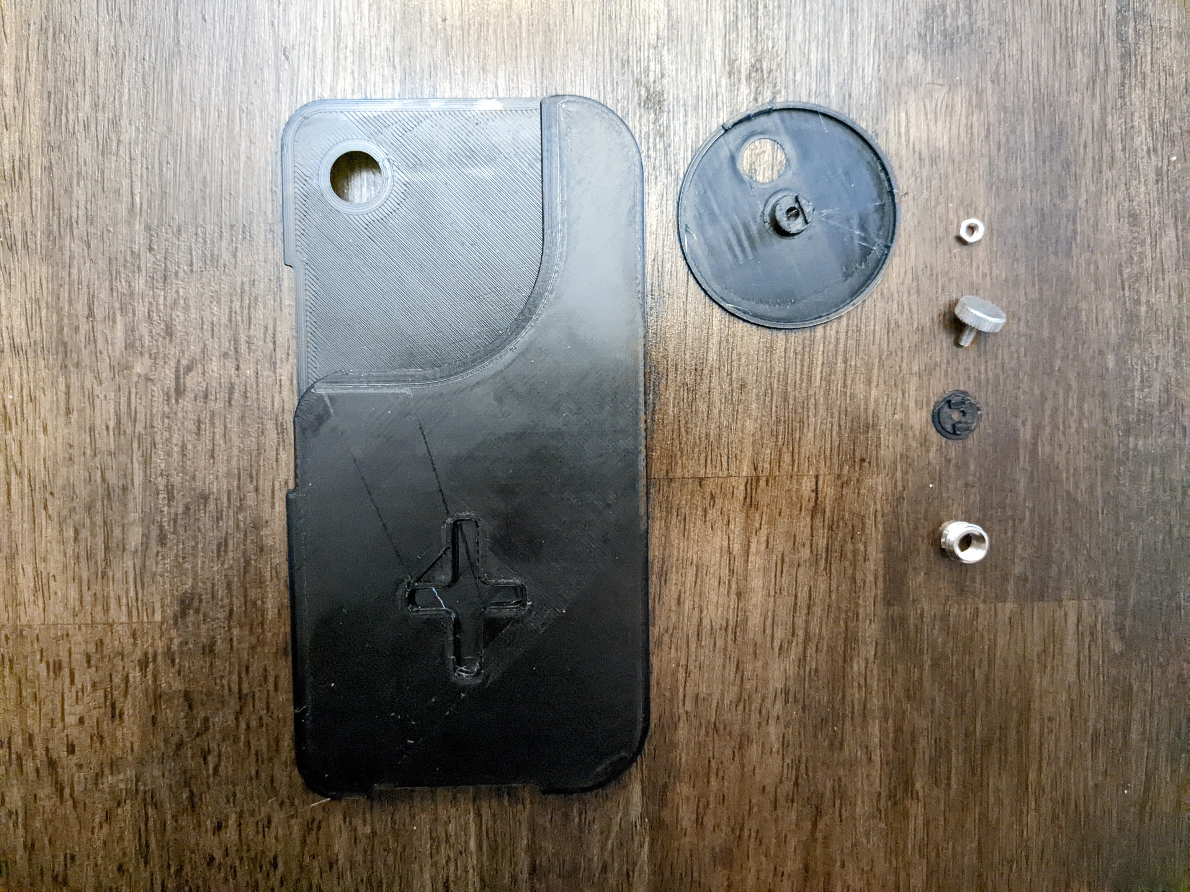
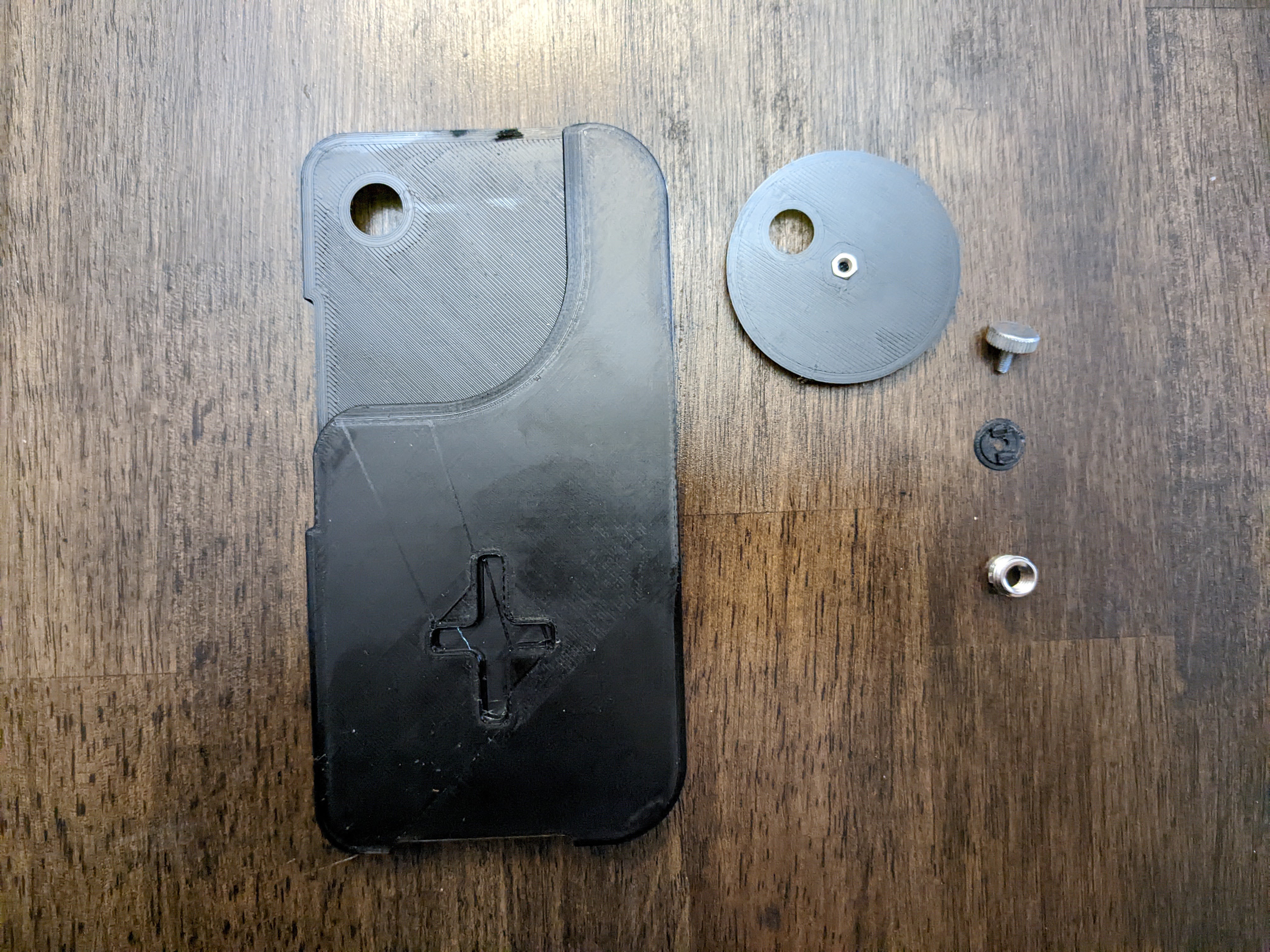
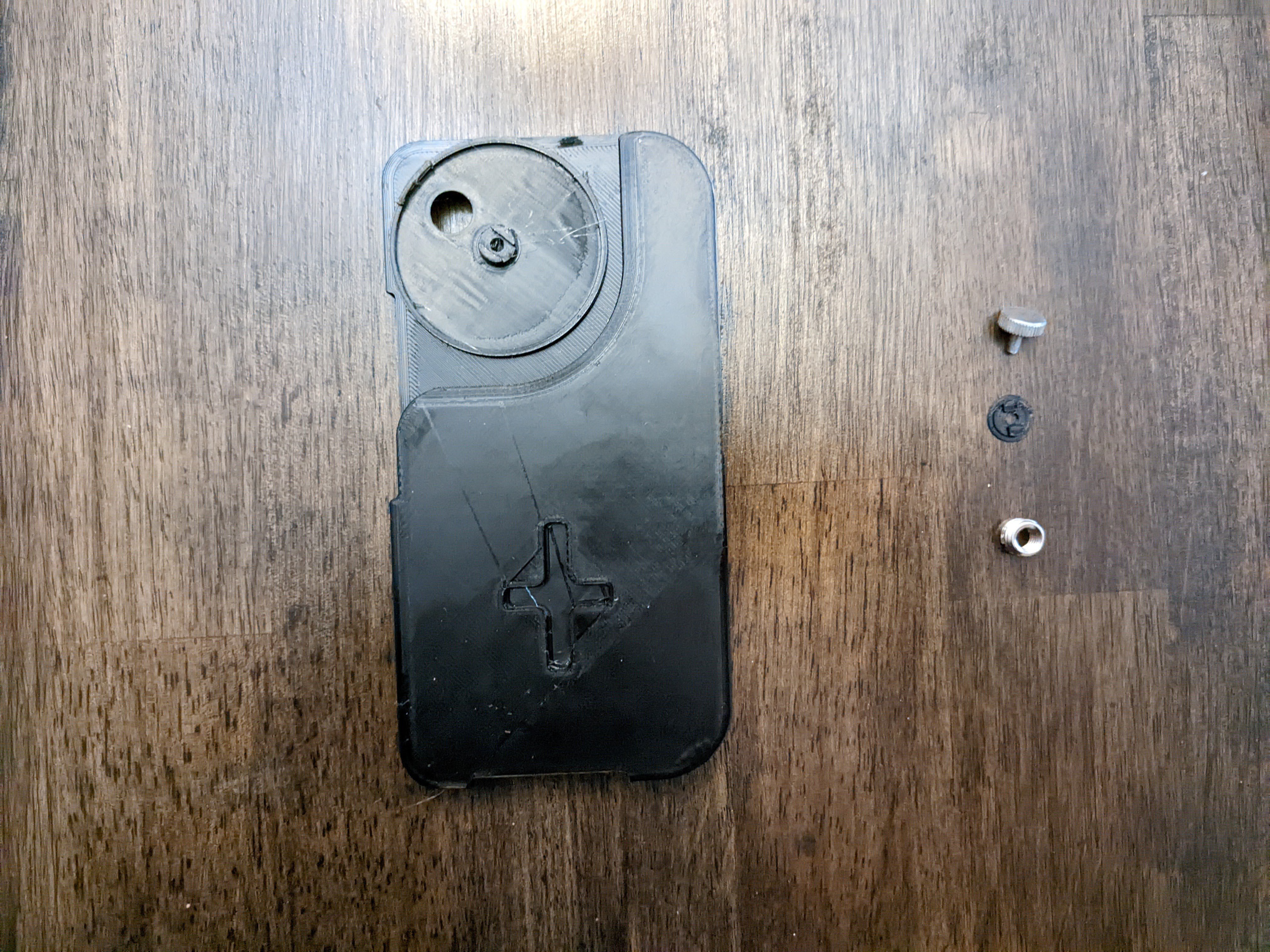
My goal is to create an entire analysis system that uses a smartphone for the user interface and the processing power. I am working on building swappable filter wheels for different analysis methods (sets of bandpass filters for subtractive imaging, etc.), wheels for macro photography/microscopy, and interchangeable modules for led lights, sensors, and spectrometers.

FalseColorIRatn.atn

Photopea actions for false color infrared. Includes auto align and channel swapping.

atn - 3.61 kB - 10/22/2022 at 01:37

Download

FilterWheelBase4.stl

Base that attaches to case back and holds filter wheel.

Standard Tesselated Geometry - 210.82 kB - 10/20/2022 at 17:29

Download

FilterWheelNut4.stl

Nut for under the filter wheel

Standard Tesselated Geometry - 90.12 kB - 10/20/2022 at 17:28

Download

Gerber_PCB_1wLEDModule_2022-09-15.zip

Gerber file for LED module prototype for surface mount LEDs. Includes through-hole points for testing with various resistors, potentiometers, and switches.

x-zip-compressed - 9.85 kB - 10/20/2022 at 16:21

Download

LEDmoduleTop1.stl

Thin diffuser top for LED modules. Printed in white.

Standard Tesselated Geometry - 335.63 kB - 10/20/2022 at 16:18

Download

View all 11 files

  • 1 × Pixel 3a
  • 1 × 3/8" to 1/4" tripod adapter
  • 1 × 10mm bandpass filters (1 each) 365 400 450 532 550 650 740 850 900 940 740nm longpass IR/UV cut Polarized
  • 2 × LED PCB Gerber in Files
  • 9 × 1W surface mount LEDs White (6000k) 365nm 850nm 940nm Full Spectrum

View all 13 components

  • Taking a set of multiband images

    Sean Billups10/22/2022 at 12:35 2 comments

    For multispectral image analysis, I am using the set of wheels with bandpass filters from 365--940nm. Taking a full set of photos allows software to map the spectral curve of various materials in that range, and, depending on the material, can reasonably identify or narrow down ID possibilities.

    Limited a bit by space, these are some sample images taken with the visible range filter wheel:

    450nm:

    550nm:

    650nm:


    After taking a full set of images with each bandpass filter, I will put them through multispectral imaging software to process the spectral curves and allow me to narrow down material IDs.

  • Testing LED light modules

    Sean Billups10/22/2022 at 12:31 0 comments

    Got to test out the LED modules. I made a UV (365nm) and an IR (850nm) module, both of which serve different purposes and enable different types of analysis.

    The IR and UV light modules snap onto the magnetic back and plug into the USB port.

    UV fluorescence, showing optical brighteners in the paper.

  • Bandpass filter wheels

    Sean Billups10/22/2022 at 12:27 0 comments

    It's Christmas already!

    I got the full set of bandpass filters in the mail, and got to start assembling specific filter wheels.

    The filters range from 365nm-940nm, roughly every 50nm. I started with the IR wheel, which includes 940, 900, 850, and 780nm. This allows me to separate out materials based on their opacities at these wavelengths.

    Assembling filters wheels with all of the bandpass filters will allow me to use the smartphone to do multiband imaging for pigment/material analysis.

  • Soldering UV and IR LED modules

    Sean Billups10/20/2022 at 17:37 0 comments

    I made a PCB for prototyping the LED modules. This is my first PCB, so it's very simple, but the through hole points allow for soldering in header pins & testing various configurations of resistors/potentiometers/switches, etc.

    I used a few USB-C OTG cables to wire up to the PCB, cutting out the data wires.

    First, the IR module: I made the 850nm module first, since that is the wavelength of bandpass filter that has been the most consistently useful in my tests. The PCB has an array of 9 LEDs in a grid, which has given enough output for photos up to 5-6 feet away from the surface.


    Next, the UV module, which needed to be mounted on top, without the diffuser over it, because the shorter UV wavelengths won't go through the diffuser.

  • Integrating with Photopea for auto FCIR

    Sean Billups10/20/2022 at 16:33 0 comments

    My end goal is to integrate with the Photopea API for automatic photo processing for various types of technical imaging.

    So far, I have made a set of actions with can be loaded into Photopea, and opened whenever the device opens the web page. Add a couple of other steps, and this allows for creation of a FCIR photo in as little as 2 minutes.

    First: take and load in the visible light photo and IR photo overlaid on top.

    Second: apply actions which auto align and swap channels.

    Third: copy and past IR layer into Red channel of vis layer. Done!

    False color infrared photo.

    I hope to work out how to apply these actions via the Photopea API, which will make FCIR even easier and quicker.

  • Tests at the MET

    Sean Billups09/26/2022 at 13:33 0 comments

    I got the opportunity to test the camera at the MET, and got a few good examples of Infrared Reflectography and inpainting on a few paintings.

    .                             

                                   Visible

    .

                    Infrared Reflectography
    (notice the dark line through the
    middle--that's inpainting at
    a split in the wood panel)
                                    Visible


                      Infrared Reflectography
                   (notice pencil grid lines)
    .                           
                                    Visible

    .

                      Infrared Reflectography
    (notice faint vertical pencil
    lines around most of the figures)

  • Case Progress

    Sean Billups07/19/2022 at 20:20 0 comments

    I've been working a lot on the case, trying to find ways to slim it down and increase its functionality. I ended up designing a magnetic mount that allows attachment of various modules, and only adds 4mm to the overall thickness. Overall, it's no bigger than a standard battery case.

    I used particularly strong magnets to give a secure hold, and the raised design helps to align the mount and hold everything in place when attached. The only way to pull it apart is straight out; the effects of side knocks & twisting are minimized.

    The case includes the filter wheel, a tripod mount, and a self-aligning magnetic mount. I'm planning on making 'magmount' tiles for additional modules, my Openflexure microscope, and a photogrammetry turntable.

  • Case and LED module tests

    Sean Billups06/28/2022 at 00:58 0 comments

    I've been working on modeling a case to include the filter wheel, removable LED light panels, and a tripod mount. It's been a slow process because I've had to learn Fusion 360 for this project.

    But I finally got the first test prints, and it's all fitting together better than I had expected for a first go around.

                                                     Mounted on a tripod, with LED module. 

                                       I only have white LEDs wired up, but next is UV and IR LEDs.


  • Removing the IR filter

    Sean Billups06/10/2022 at 16:34 0 comments

    Removal of the IR filter took a lot of trial and error--some camera modules are less suitable for modification than others, and I had to figure out a good process by which to disassemble them.

    For the Pixel 3a camera, I tried using a scalpel to separate the sensor from the lens housing, but this ended up breaking some very tiny solder joins that connected to the autofocus mechanism in the lens housing. If it didn't have autofocus, it would have been no problem!

    I tried soldering those broken joins, but they were too small and beyond my soldering skills.

    In order to avoid breaking them in the first place, I settled on using a heated 3d printer bed to soften the adhesive around the lens (15 min. on 60C), and using a small pair of pliers to twist and remove the lens. This gave me access to the IR filter, which is glued into a square frame just above the sensor.

    To remove the IR filter, I glued a small section of ABS 3d printer filament to it to pull it out.

    It ended up breaking instead.

    But, after carefully removing the rest of the broken IR filter, I was able to twist the lens back in place and put the camera module back into the phone without an issue.

                                                   Disassembled phone and camera modules

                                        Camera module with lens removed, showing broken IR filter

                                                      Camera module after removal of IR filter.

    I'm going to try printing a small tool to adhere better to the IR filter, and hopefully with some heat, I'll be able to pull out the filter intact.

  • Successful removal of IR filter

    Sean Billups06/06/2022 at 17:21 0 comments

    I have managed to safely remove the integrated IR filter in the Google Pixel 3a phone--the method: a heated 3d printer bed, set at 60C, is used to soften the adhesive that holds the lens in place. After about 15-20 minutes, the lens is carefully and slowly twisted with a small set of pliers until it comes out.

    To remove the filter, I have been using a small amount of adhesive (superglue or a quick-setting epoxy) on the end of a small section of 3d printer filament. I glue this piece onto the filter itself, allow it to cure, then set the camera back on the printer bed and pull the filter out.

    I have broken several filters, though, and have had to carefully remove all traces of broken glass from inside the camera module.

    But despite the fact that I need to refine my technique, it works!

    The filter wheel is printed in PETG, and designed to house 4 filters that enable up to 7 types of technical imaging: Visible, Raking light, UV fluorescence, UV reflectography, IR reflectography, IR fluorescence, and Polarized.

                                                               Painting in visible light

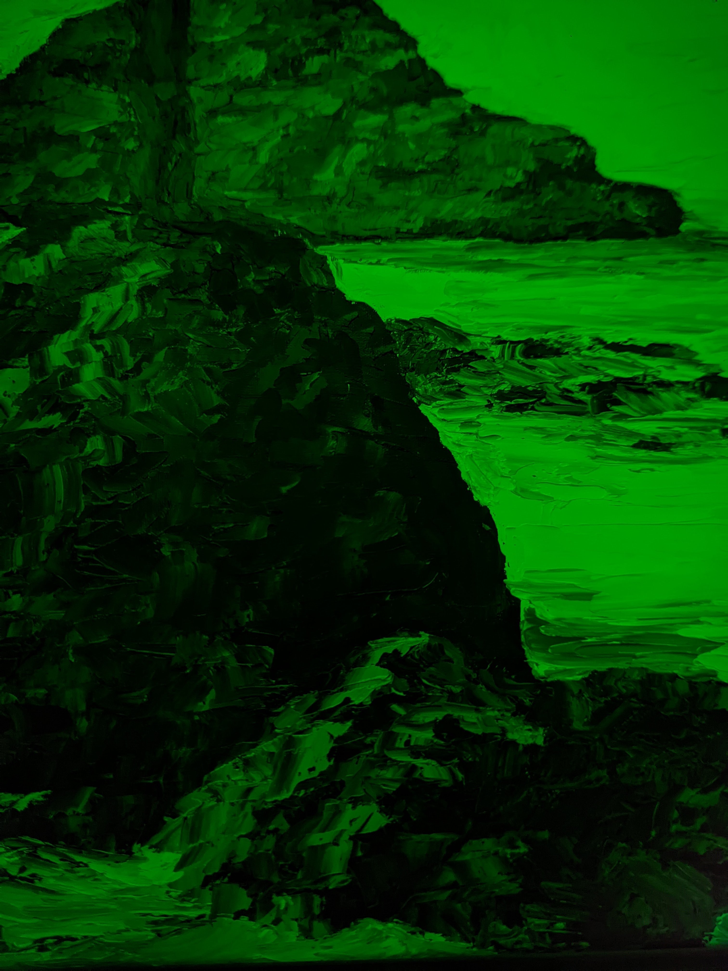
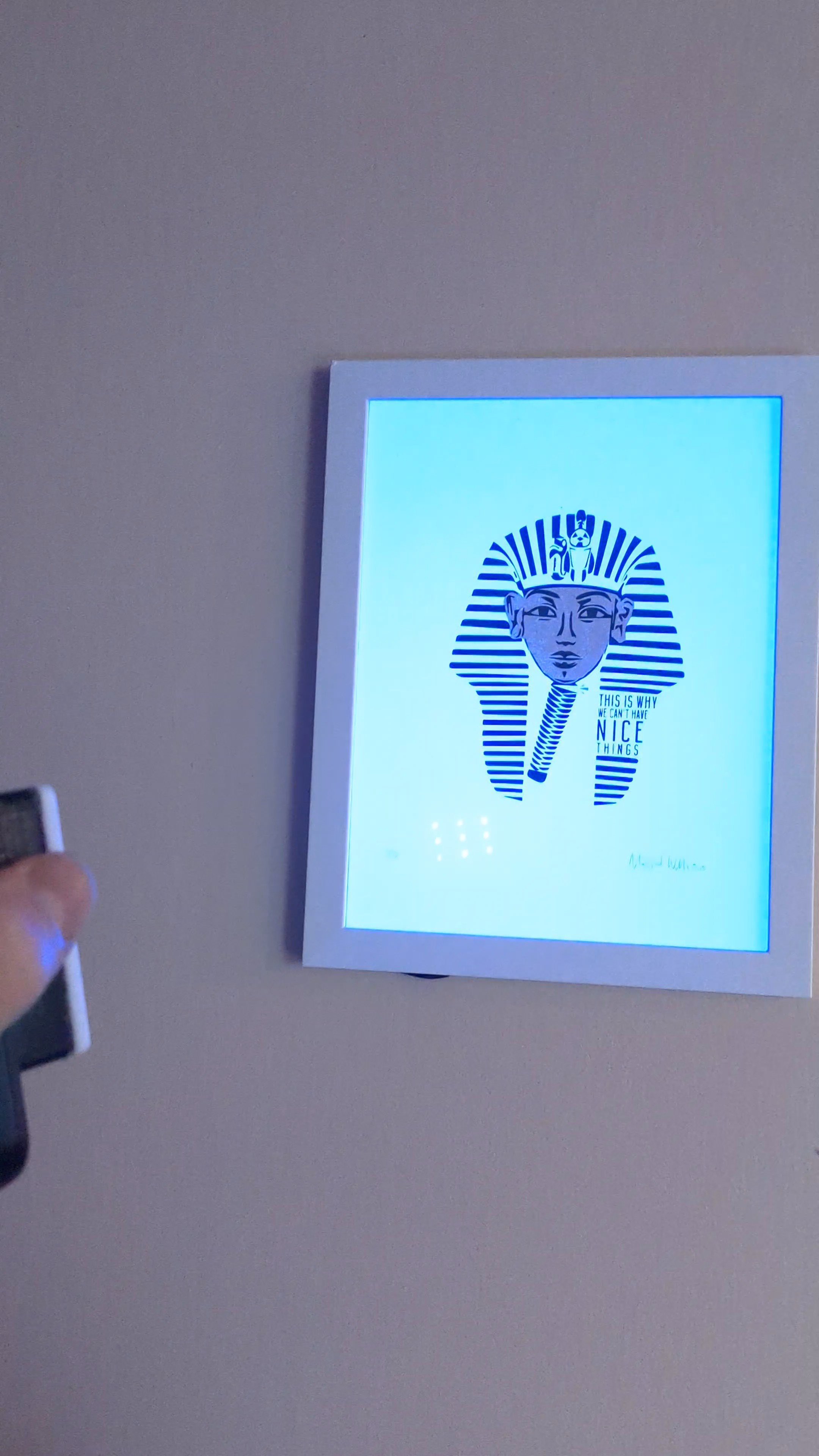
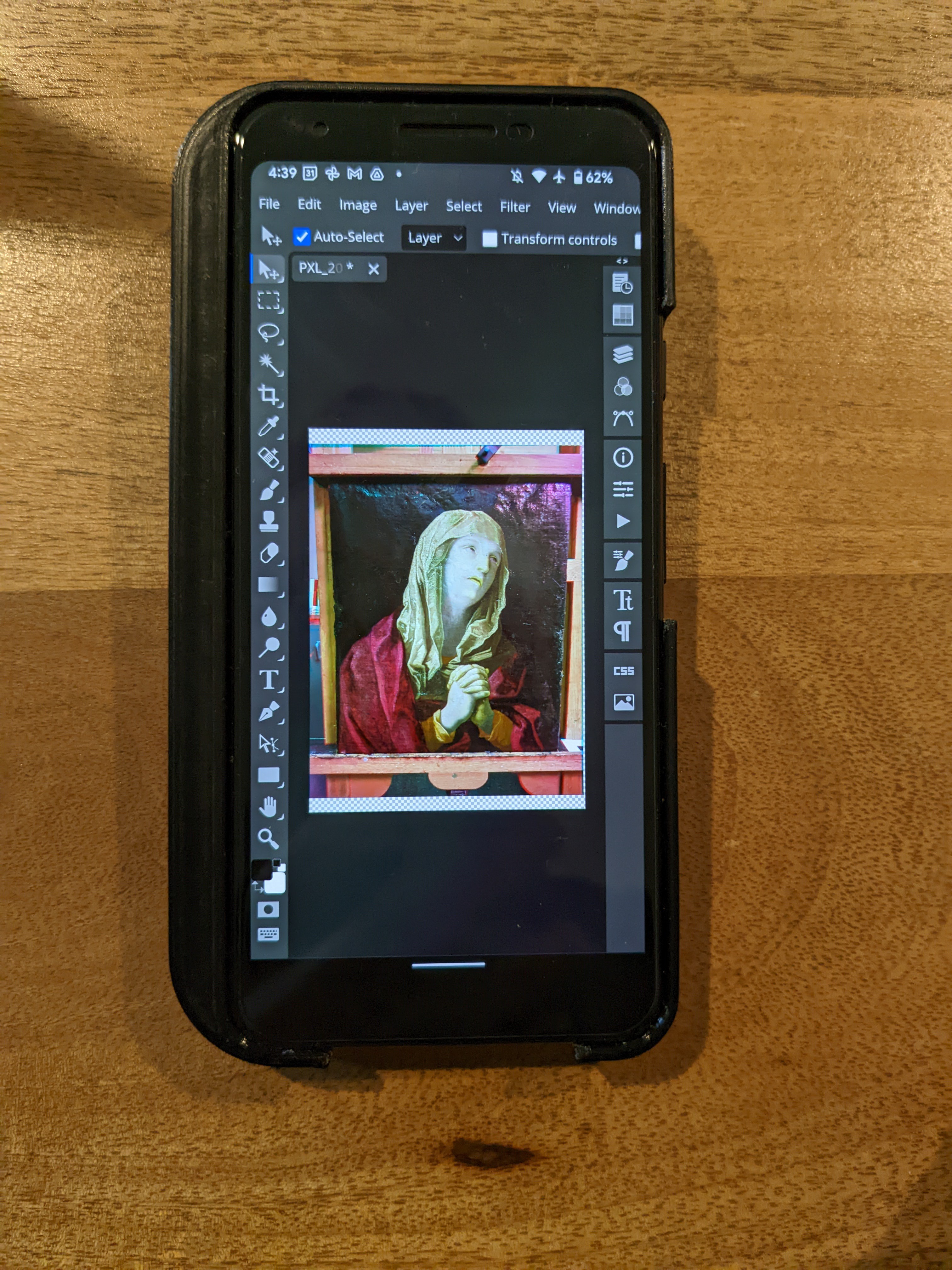
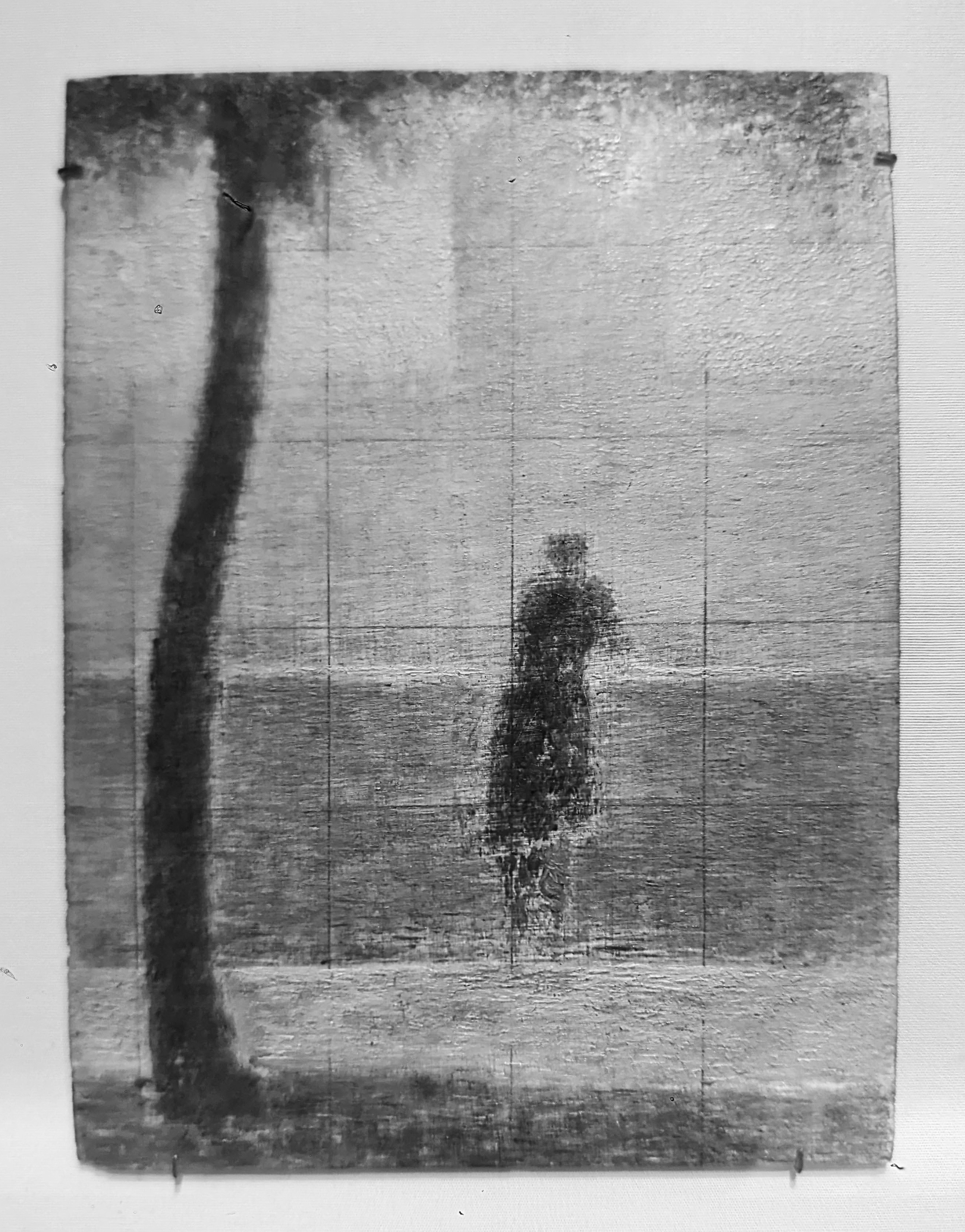
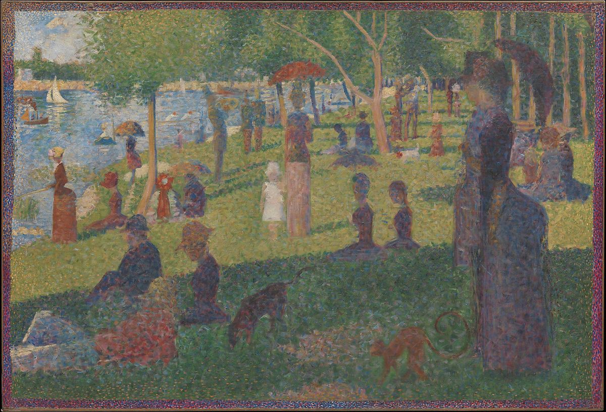
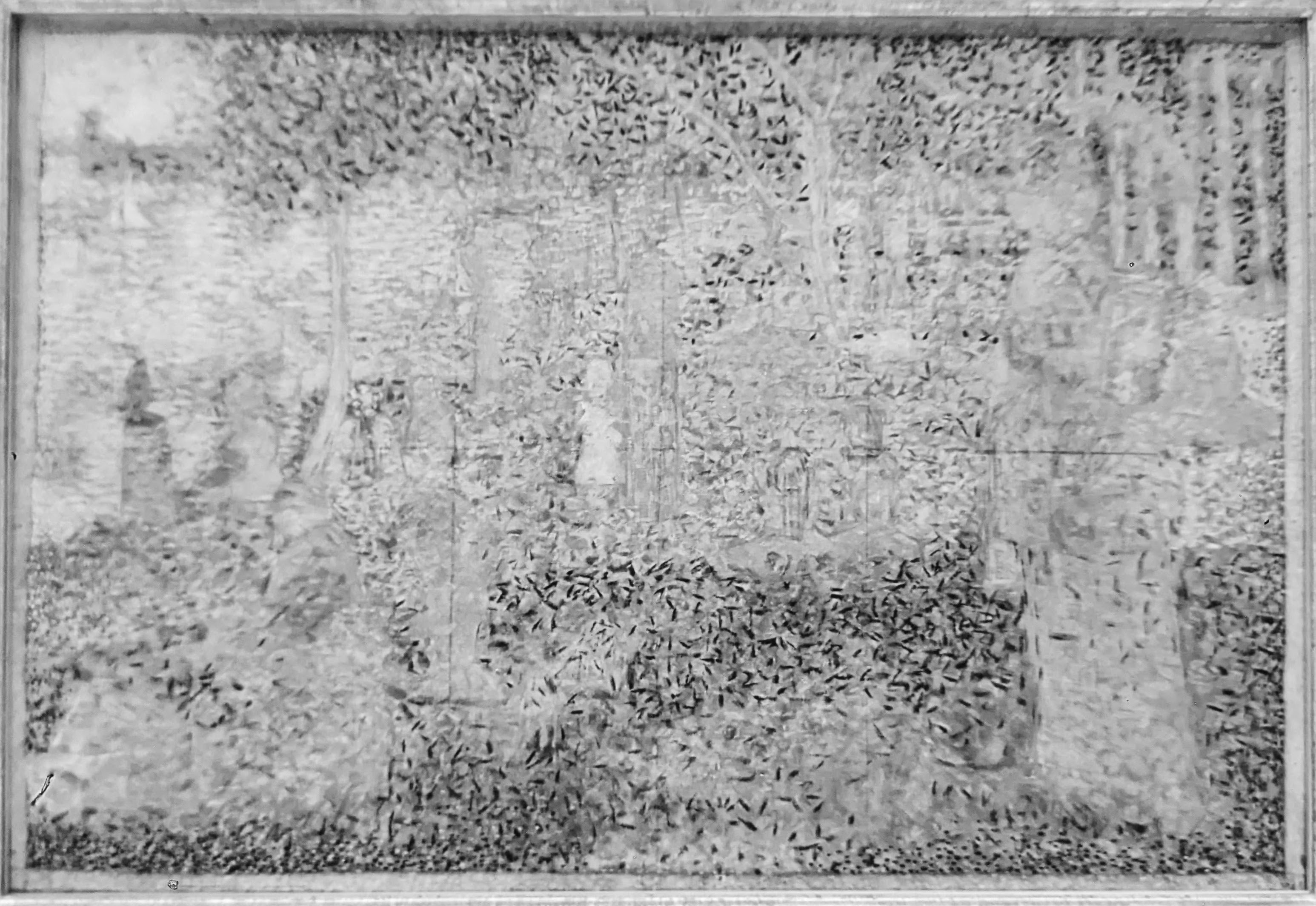
                                               Same painting in UV reflectography. Note the difference                                                                                     between 2 different white paints.


View all 10 project logs

  • 1
    Removing the camera

    The first step is the remove the camera from the Pixel 3a phone. The screen on this phone is pretty thin, so care should be taken.

    There are plenty of extensive descriptions of this process elsewhere online, so I will be brief.

    Separate the screen from the body with a thin tool. I prefer to cut up plastic food containers for these separator tools, because they are just thin and flexible enough to get inside the glue line, and stiff enough to cut through the adhesive.

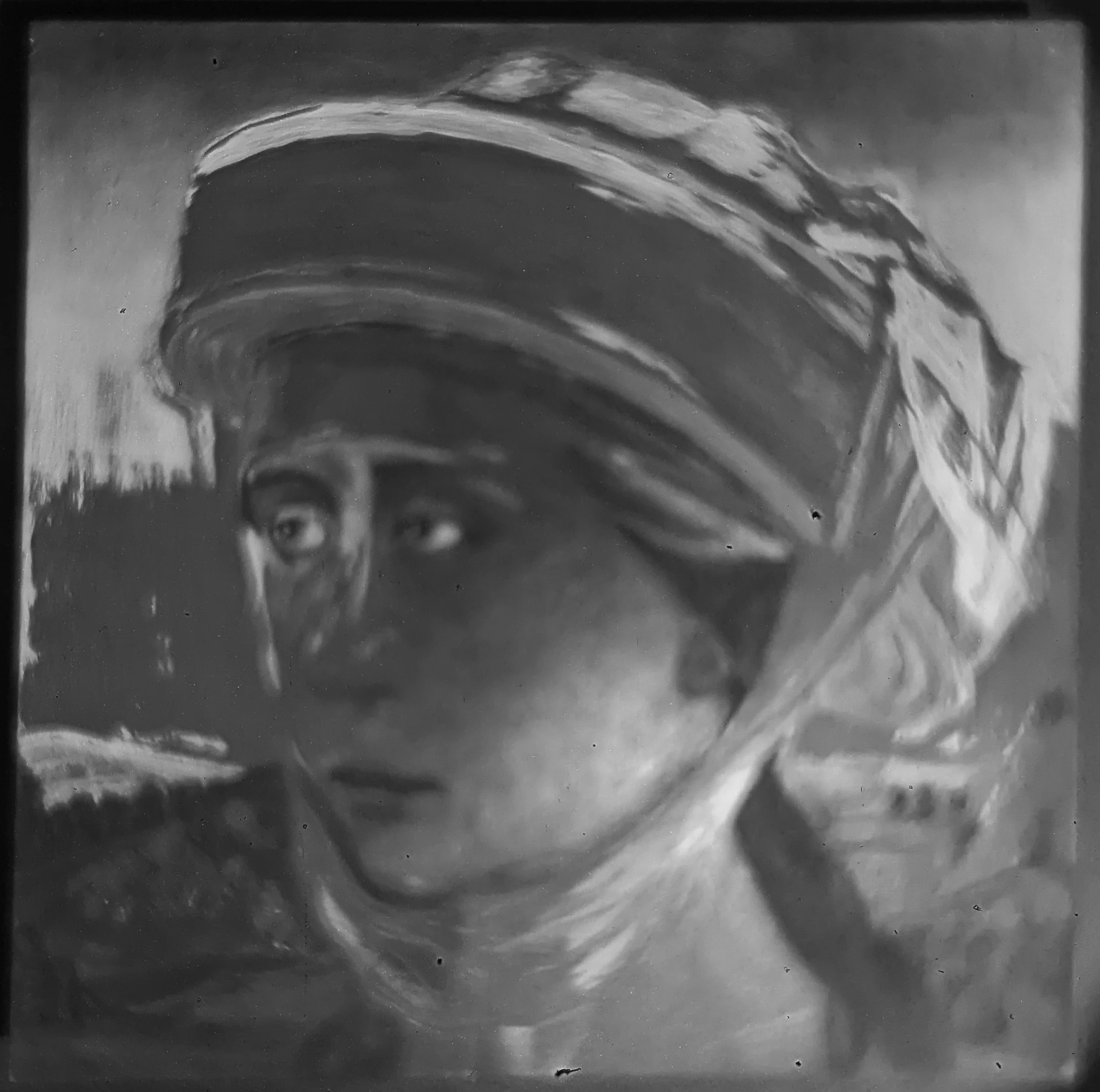
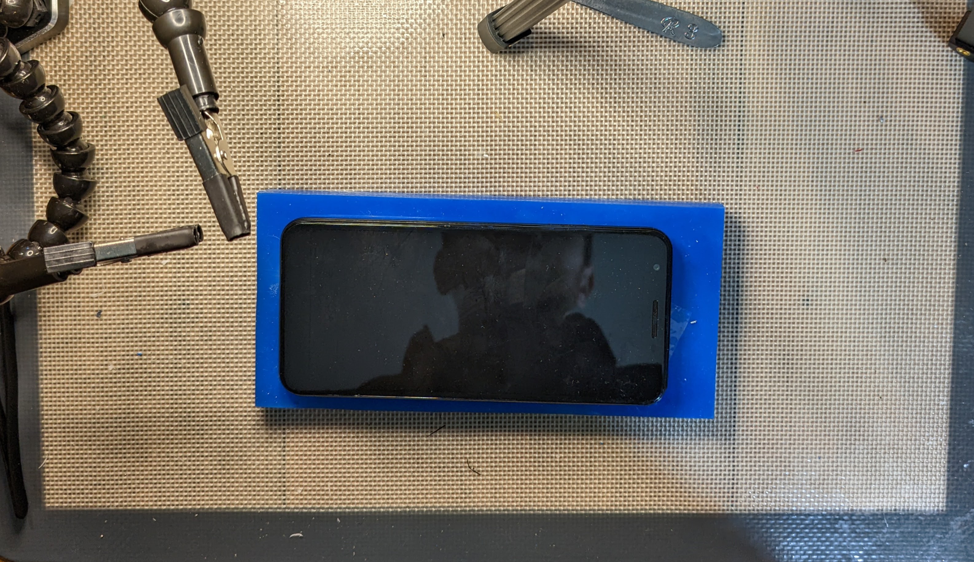
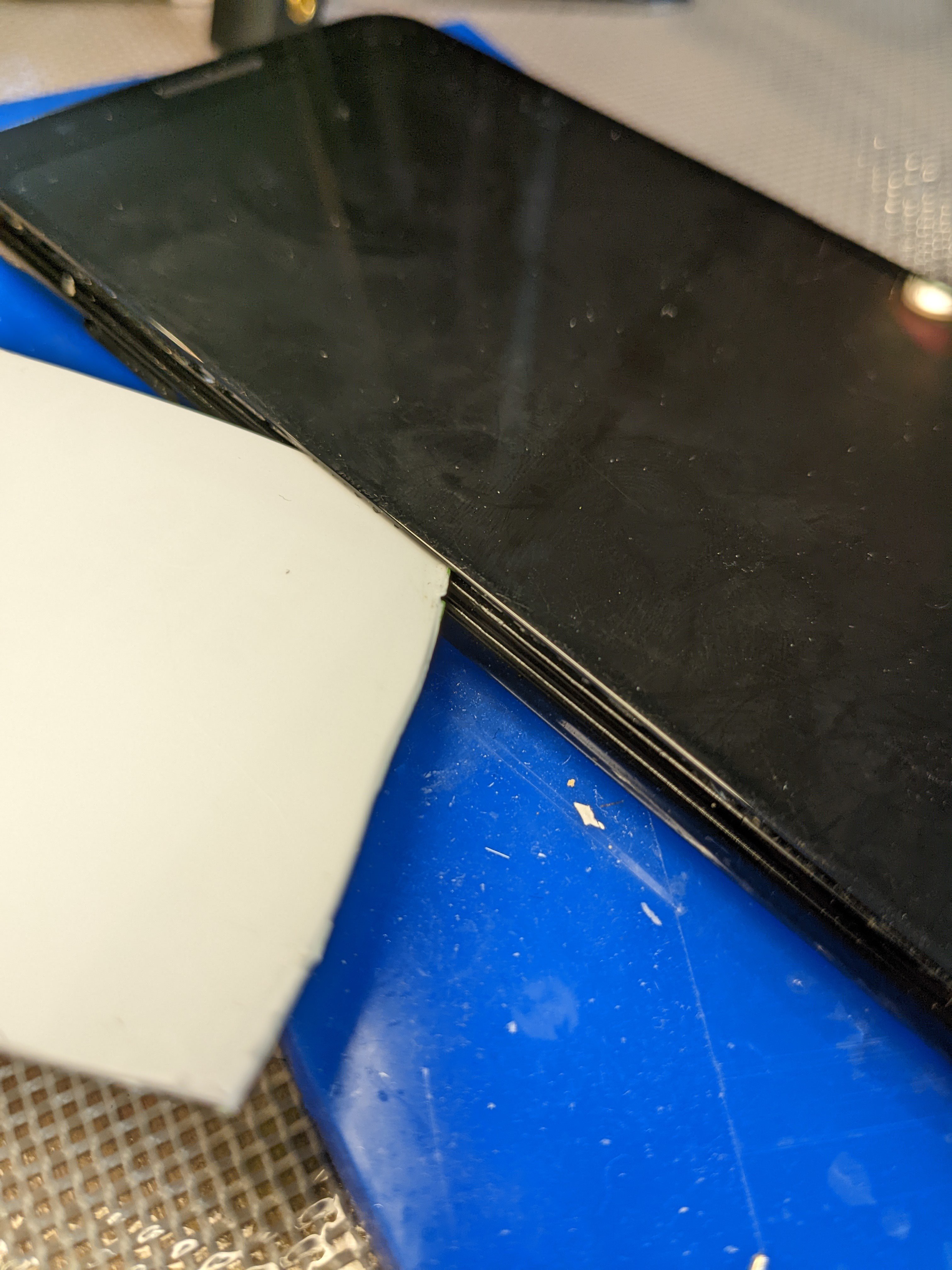
    Lift the screen away from the body. The adhesive tape is the only thing holding the screen on. No screws or snaps.
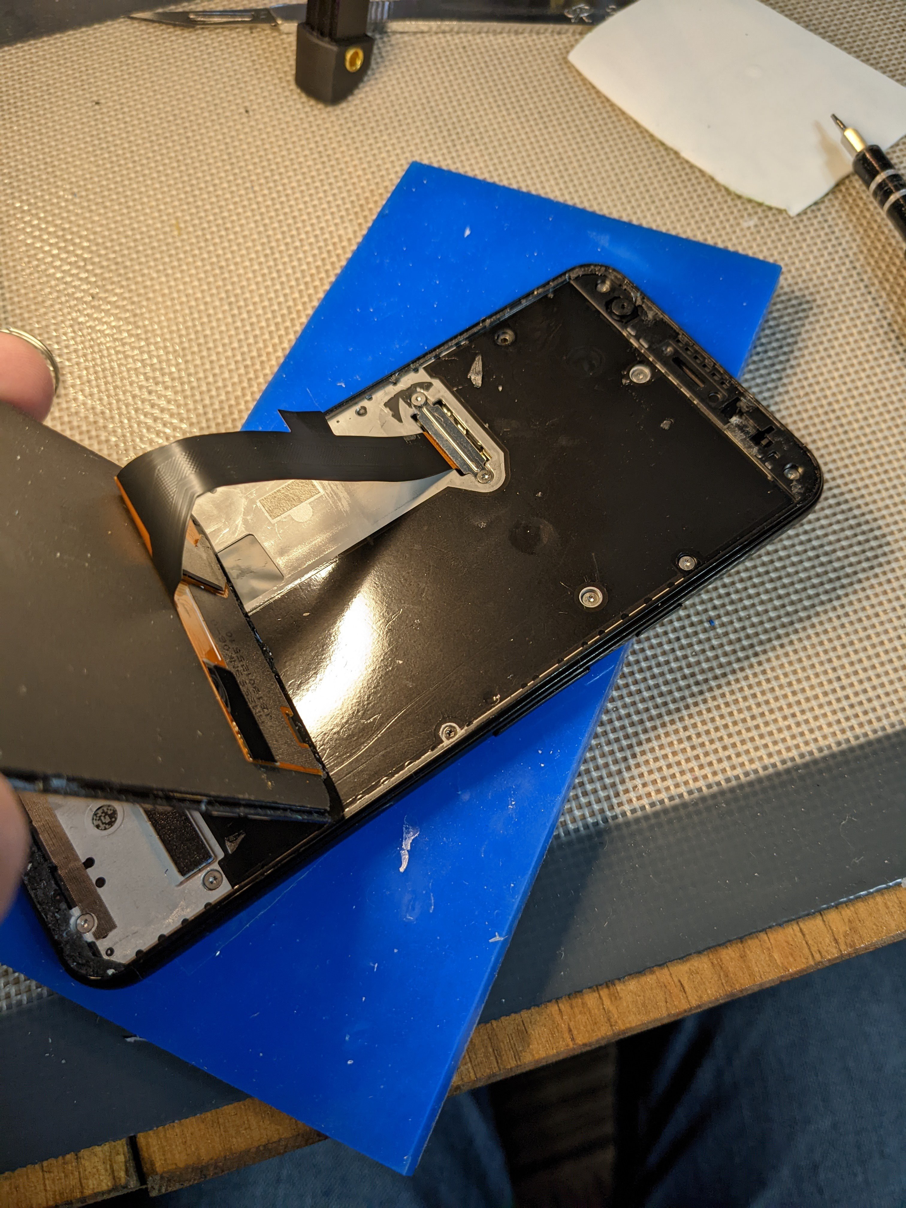
    Remove the screws all around the mid plate, and pry the mid plate away from the rest of the body. There are snaps near the top and bottom of each side.

    Lift the mid plat away, detach the battery connections (for the safety of the motherboard), and the camera is easily removed.

  • 2
    Removing UV/IR cut filter

    This step is the tricky part.

    I have found that removing the lens is relatively easy when the camera is heated a bit with some denatured alcohol to soften the adhesive.

    I use the heated bed of my 3d printer set to 60c, put the camera face down with a few drops of denatured alcohol underneath the camera, and cover it to keep the heat in and allow the alcohol to permeate the air inside the chamber.

    After about 15min, pull it out and test the adhesive with a small pair of pliers by carefully twisting. It is easy to damage the miniscule wires holding the lens ring in place if too much force is used or if it is lifted out instead of twisted.

    If the lens does not turn with light to moderate pressure, put it back on the heated bed, a bit more alcohol, and 10 more minutes. 

    When the lens starts to twist, apply gentle pressure upwards as you twist, and slowly work it up and out.

    Once the lens is out,  the UV/IR cut filter can be seen.

    Put it back on the printer bed for another 10 minutes to make sure all the alcohol is evaporated. If the alcohol touches the sensor, the camera is likely done for.

    My method of removing the filter entails supergluing a small 1" section of 3d printer filament onto the filter, allowing it to fully dry, then pulling the filament out. This usually results in a broken filter, and care needs to be taken to remove all of the pieces without touching the sensor. It's tough work.

    Once it's all removed, the camera and be reassembled, taking care to set the lens exactly at the height it was before.

    Then the phone can be reassembled.

  • 3
    Print and assemble phone case

    Printing of all parts is done is PETG.

    All parts needed for assembly of case:

    Case

    Case back/magnetic attachment

    Filter wheel base

    Filter wheel nut

    M3 thumb screw

    M3 nut

    3/8" to 1/4" tripod mount adapter

    8x3mm magnets (x4)

    -----------------------------------

    Insert magnets:

    Adhere back onto case (I use superglue with 3d prints):

    Insert M3 nut into back of filter wheel base:

    Adhere filter wheel base into place:

    Insert tripod mount adapter (I use epoxy for this step):


View all 4 instructions

Enjoy this project?

Share

Discussions

Similar Projects

Does this project spark your interest?

Become a member to follow this project and never miss any updates